1
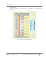
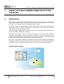
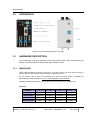
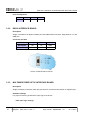
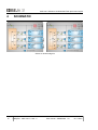
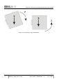
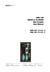
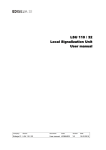
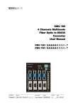
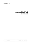
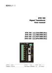
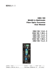
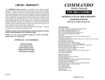
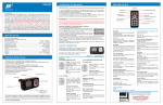
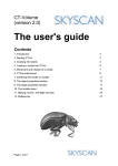
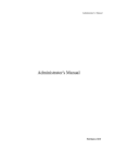
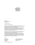
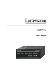
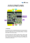
CMU 100 RS232 to 2x Multimode Fiber Optic Star Coupler User Manual CMU 100 / 2.1.6.6 - 2 CMU 100 / 8.1.6.6 - 2 Company: Device: Ediseja 21 CMU 100 / 2.1.6.6 - 2 Document: Code: Version: User manual CMUMU226 V3 Date: 05.11.2015 CMU 100 - RS232 to 2x Multimode Fiber Optic Star Coupler Content 1 PREFACE.......................................................................................................3 2 CMU 100 SYSTEM.........................................................................................6 2.1 DESCRIPTION..................................................................................................................... 6 2.1.1 SOFTWARE...................................................................................................................... 6 2.1.2 HARDWARE...................................................................................................................... 6 3 RS232 TO 2x MULTIMODE FIBER OPTIC STAR COUPLER.....................8 3.1 DESCRIPTION..................................................................................................................... 8 3.2 APPEARANCE..................................................................................................................... 9 3.3 HARDWARE DESCRIPTION............................................................................................... 9 3.3.1 MAIN BOARD.................................................................................................................... 9 3.3.2 RS232 INTERFACE BOARD...........................................................................................10 3.3.3 MULTIMODE FIBER OPTIC INTERFACE BOARD.........................................................10 4 SCHEMATIC.................................................................................................12 5 INSTALLATION............................................................................................13 5.1 INSTALLATION.................................................................................................................. 13 6 COMMISSIONING & MAINTENACE..........................................................15 6.1 COMMISSIONING.............................................................................................................. 15 6.2 MAINTENANCE................................................................................................................. 15 7 TECHNICAL DATA......................................................................................16 8 DIMENSIONS...............................................................................................18 9 ORDERING...................................................................................................19 Page: Company: Device: 2 Ediseja 21 CMU 100 / 2.1.6.6 - 2 Document: Code: Version: User manual CMUMU226 V3 Date: 05.11.2015 PREFACE 1 PREFACE Liability statement We have checked the contents of this manual to ensure that the descriptions of both hardware and software are as accurate as possible. However, deviations may occur so that no liability can be accepted for any errors or omissions contained in the information given. The contents of this manual will be checked in periodical intervals, corrections will be made in the following editions. We reserve the right to make technical improvements without notice. Contact If you have any questions or comments related to this product please contact us on: Ediseja 21 d.o.o. Drenov Gric 175 1360 Vrhnika Slovenia – EU Tel: 00 386 51 643 411, 051 643 411 Email: [email protected] www.ediseja21.com Copyright Copyright © Ediseja 21, 2013. All rights reserved. Explanation of the symbols Read the instructions! Device was tested with 2,5 kV AC voltage to check the device insulation. Device ground terminal. Waste Electrical and Electronic Equipment (WEEE) Directive 2002/96/EC; the affixed product label indicates that you must not discard this electrical/electronic product in domestic household waste. Company: Device: Ediseja 21 CMU 100 / 2.1.6.6 - 2 Document: Code: Version: User manual CMUMU226 V3 Date: 05.11.2015 Page: 3 CMU 100 - RS232 to 2x Multimode Fiber Optic Star Coupler Warnings In this paper the following terms are used: Danger indicates that death, severe personal injury or substantial property damage will result if proper precautions are not taken. Warning indicates that death, severe personal injury or substantial property damage can result if proper precautions are not taken. Caution indicates that minor personal injury or property damage can result if proper precautions are not taken. This particularly applies to damage on or in the device itself. General information These paper contain the information that is necessary for the proper and safe operation of the described devices. This paper is intended for technically qualified personnel. Warning! Hazardous voltage is present inside the device during operation. Disregarding of safety rules can result in severe personal injury or property damage. Only qualified personnel may work with described devices after being familiar with warnings and safety notices in this paper and other safety regulations. Warning! Device must operate completely assembled! Device must be used as described. No modifications of the device should be made. Warning! Do not open device while it is energized! Hazardous voltage is present inside the device. Disconnect all connectors before opening! Page: Company: Device: 4 Ediseja 21 CMU 100 / 2.1.6.6 - 2 Document: Code: Version: User manual CMUMU226 V3 Date: 05.11.2015 PREFACE Warning! If device is damaged disconnect it from power supply! Send it to the manufacturer for inspection. Warning! Connect to earth before attaching power supply! Company: Device: Ediseja 21 CMU 100 / 2.1.6.6 - 2 Document: Code: Version: User manual CMUMU226 V3 Date: 05.11.2015 Page: 5 CMU 100 - RS232 to 2x Multimode Fiber Optic Star Coupler 2 CMU 100 SYSTEM 2.1 DESCRIPTION Communication unit (CMU 100) is modular system of communication devices that can be used for various of tasks such as: communication converter (for example RS232 to RS485) star coupler (for example 1 fiber optic to 7 fiber optics) repeater (for example RS485/485) communication isolator (for example for preventing ground loops) communication listener - debugger PC serial com port extender (for example USB to 4 serial com) CMU 100 device is a couple of software and hardware. For different purposes, different software versions and different hardware configuration have been developed. 2.1.1 SOFTWARE Software is application dependent and allows different hardware configurations. Software's task is switching between communication ports and allows almost any combination between them. 2.1.2 HARDWARE Hardware is based on main board with power supply and port switching logic. On that board, interface boards are attached. CMU 100 can handle up to 8 different interface boards. Currently available interface boards: RS232 isolated RS485 Multimode Fiber Optic ST and SMA connectors USB ethernet (with one virtual com port) Housing is aluminium and intended for mount on standard DIN 35 rail (acc. to DIN EN 50022). 3 different housings have been made. Depends on how many interfaces device has, appropriate housing is used. Page: Company: Device: 6 Ediseja 21 CMU 100 / 2.1.6.6 - 2 Document: Code: Version: User manual CMUMU226 V3 Date: 05.11.2015 DESCRIPTION Hardware settings All settings on the device can be made from outside by a DIL switch. It is not necessary to open the housing. Picture 1: CMU 100 system general diagram Company: Device: Ediseja 21 CMU 100 / 2.1.6.6 - 2 Document: Code: Version: User manual CMUMU226 V3 Date: 05.11.2015 Page: 7 CMU 100 - RS232 to 2x Multimode Fiber Optic Star Coupler 3 RS232 TO 2x MULTIMODE FIBER OPTIC STAR COUPLER 3.1 DESCRIPTION Star coupler is communication device that transfer data from one (master) to more than one (slave) port. Example is when we need access to one device with several PCs. It can also be used when communication from PC to multiple devices is needed. This device contains one RS232 interface (master) and two 820 nm wave lenght multimode fiber optic (slaves). Data is send from master port to all slave ports. On the other hand, data from either slave port is send to master port only. Wide power supply voltage allows connection to all common station batteries. Additionaly it can be also connected to standard AC voltages. This device is intended for use in cubicles and cabinets in all kinds of power production, transmission and distribution stations. It requires no maintenace. All normaly used connectors, switches and light indicators are accessed at the front side of the device. One light indicator indicates power supply voltage, others indicate communication transfer. Fiber optic communication allows longer distances between devices without electromagnetic disturbances. Fiber optic logic can be set to positive or negative logic for transmitter and receiver separatedly. They can be set by DIP switch at the front side of the communication interface. TYPICAL APPLICATION Picture 2: Typical application Page: Company: Device: 8 Ediseja 21 CMU 100 / 2.1.6.6 - 2 Document: Code: Version: User manual CMUMU226 V3 Date: 05.11.2015 APPEARANCE 3.2 APPEARANCE Picture 3: Front view (left) & bottom view (right) 3.3 HARDWARE DESCRIPTION This configuration of device is made from main board (power supply, LEDs, switches and logic switch), one RS232 and two multimode fiber optic interface boards. 3.3.1 MAIN BOARD Power LED indicates that device is turned on. The right LEDs of one port shows activity on receive (Rx) line and the left one shows activity on transmit (Tx) line. On the bottom side of device are switches and JTAG connector which is intended for downloading necessary software. Do not connect anything to that connector. Additional switches allows echo on each port. Echo can be set on or off for each port. Switches Company: Switch 1 2 3 4 Description Echo port 1 Echo port 2 Echo port 3 Device mode Position OFF Echo off Echo off Echo off Star coupler Position ON Echo on Echo on Echo on Comm. node Default position OFF OFF OFF OFF Device: Ediseja 21 CMU 100 / 2.1.6.6 - 2 Document: Code: Version: User manual CMUMU226 V3 Date: 05.11.2015 Page: 9 CMU 100 - RS232 to 2x Multimode Fiber Optic Star Coupler Ports Configuration 3.3.2 Port 1 2 3 Interface RS232 FO MM FO MM RS232 INTERFACE BOARD Description Single, nonisolated, full duplex, RS232 port with DB9 female connector. Supported Rx, Tx and GND pins. Connector pin table DB9 F 2 3 5 Description RX TX GND Direction IN OUT - Picture 4: DB9 Female connector 3.3.3 MULTIMODE FIBER OPTIC INTERFACE BOARD Description Single, full duplex, multimode, fiber optic port with ST connectors with positive or negative logic. Hardware settings For proper functioning of that board, optic logic must be set: Fiber optic logic settings Page: Company: Device: 10 Ediseja 21 CMU 100 / 2.1.6.6 - 2 Document: Code: Version: User manual CMUMU226 V3 Date: 05.11.2015 HARDWARE DESCRIPTION Switch SW1 Light in idle state 1 2 3 4 Positive logic OFF OFF ON OFF ON Negative logic ON ON OFF ON OFF Picture 5: Multimode fiber optic interface board appearance It is recommended that positive logic on fiber optic interfaces is used (light OFF in idle state). In other case, if optic loop on one port is broken, communication with other slave ports, also will not work. Company: Device: Ediseja 21 CMU 100 / 2.1.6.6 - 2 Document: Code: Version: User manual CMUMU226 V3 Date: 05.11.2015 Page: 11 CMU 100 - RS232 to 2x Multimode Fiber Optic Star Coupler 4 SCHEMATIC Picture 6: General diagram Page: Company: Device: 12 Ediseja 21 CMU 100 / 2.1.6.6 - 2 Document: Code: Version: User manual CMUMU226 V3 Date: 05.11.2015 INSTALLATION 5 INSTALLATION 5.1 INSTALLATION Warning! Hazardous voltage is present inside the device during operation. Disregarding of safety rules can result in severe personal injury or property damage. Only qualified personnel may work with described devices after being familiar with warnings and safety notices in this paper and other safety regulations. Following instruction must be taken into consideration: Company: The device must be accessible to qualified personnel only. The device is permitted to operate in enclosed housing or cabinet only. The device location must be vibration-free. The admisible operating temperature must be observed. Check the device for damage at unpacking. If device is damaged it must not be installed but it should be send to the manufacturer for repair. The device should not be opened. The device should be mounted on a 35 mm rail (acc to EN 50022). Attach ground wire before attaching power supply. Device must be grounded during operation! Single core or stranded wire 0,5 – 2,5 mm 2 must be used for power supply connection. If stranded wire is used, ferrules must be used to prevent fraying. Recommended stripping lenght is 5 mm. Protective earthing wire must be terminated with tinned copper ear terminal. The prescribed bending radius of the optical fibre cables must be observed. Device: Ediseja 21 CMU 100 / 2.1.6.6 - 2 Document: Code: Version: User manual CMUMU226 V3 Date: 05.11.2015 Page: 13 CMU 100 - RS232 to 2x Multimode Fiber Optic Star Coupler Picture 7: left. installation, right: deinstallation Page: Company: Device: 14 Ediseja 21 CMU 100 / 2.1.6.6 - 2 Document: Code: Version: User manual CMUMU226 V3 Date: 05.11.2015 COMMISSIONING & MAINTENACE 6 COMMISSIONING & MAINTENACE 6.1 COMMISSIONING Warning! Hazardous voltage is present inside the device during operation. Disregarding of safety rules can result in severe personal injury or property damage. Only qualified personnel may work with described device after being familiar with warnings and safety notices in this paper and other safety regulations. Following instruction must be taken into consideration: 6.2 Device must operate completely assembled! Device must be used as described. No modifications of the device should be made. Attach ground wire before attaching power supply. Device must be grounded during operation! Check if the power supply voltage complies with device operation voltage. Do not open device while it is energized! Hazardous voltage is present inside the device. If single mode fiber optic interface is used, do not look into the laser beam. MAINTENANCE The device is maintenance-free. Disconnect power supply before cleaning it. Use moist cloth. Do not use liquids. Company: Device: Ediseja 21 CMU 100 / 2.1.6.6 - 2 Document: Code: Version: User manual CMUMU226 V3 Date: 05.11.2015 Page: 15 CMU 100 - RS232 to 2x Multimode Fiber Optic Star Coupler 7 TECHNICAL DATA Power supply Rated voltage Permissible voltage range Input current Type 1 Type 7 DC 110 - 250 V 48 - 60 V AC 230 V 48 V DC 88 - 300 V 38 - 72 V AC 70 - 264 V 30 - 50 V DC 30 - 20 mA 70 - 60 mA AC 30 mA 90 mA Fuse (internal) 2AT Power supply indicator green LED marked PWR Voltage dips 20 ms Connector type screw type „MSTB“ Phoenix 2pin Wire crossection 0,5 – 2,5 mm 2 Communication port RS232 (interface type 1) Type RS232 Direction full duplex Speed up to 230 k BAUD Number of ports 1 Distance up to 15 m Isolation none; (GND earthed) Connector type DB9 female Lines in 1 (RX) Lines out 1 (TX) Communication port Multimode Fiber Optic (interface type 6) Type multimode fiber optic Wave lenght 820 nm Fiber size 50/125 μm, 62,5/125 μm, 100/140 μm, 200 μm Optical output power -18 dB Reciver sensitivity -24 dB Laser class I (IEC 60825-1) Direction full duplex Page: Company: Device: 16 Ediseja 21 CMU 100 / 2.1.6.6 - 2 Document: Code: Version: User manual CMUMU226 V3 Date: 05.11.2015 TECHNICAL DATA Communication port Multimode Fiber Optic (interface type 6) Speed up to 230 k BAUD Input 1 receiver (grey connector) Output 1 transmitter (white connector) Logic light ON or OFF in idle state set by switch (see table) Number of ports 1 Distance up to 500 m Connector type ST Device 0,35 kg Weight Dimensions (see picture) (H) (D) (W) 105 mm 111 mm + connectors 55 mm Temperature range 0 °C to +55 °C Humidity operating up to 95 % (noncondensing) Enclosure Material Al IP 20 standard DIN 35 rail (acc. to DIN EN 50022) Mount type Class I Overvoltage category II Communication indicator Company: Device: Ediseja 21 CMU 100 / 2.1.6.6 - 2 Receiveing yellow LED marked Rx Tranmitting green LED marked Tx Document: Code: Version: User manual CMUMU226 V3 Date: 05.11.2015 Page: 17 CMU 100 - RS232 to 2x Multimode Fiber Optic Star Coupler 8 DIMENSIONS Picture 8: Dimensions Page: Company: Device: 18 Ediseja 21 CMU 100 / 2.1.6.6 - 2 Document: Code: Version: User manual CMUMU226 V3 Date: 05.11.2015 ORDERING 9 ORDERING ORDERING NUMBER: CMU 100 / c . c . c . c . c . c . c . c . c - c . c Mother Board + Enclosure + : Power supply: 88 - 350 V DC or 70 - 264 V AC 2 ports converters (no echo possible, mark Function as 0) ............................................... 1 2 to 8 ports converters, star couplers, ... (echo possible) ................................................... 2 Power supply: 38 - 72 V DC or 30 - 50 V AC 2 ports converters (no echo possible, mark Function as 0) ................................................ 7 2 to 8 ports converters, star couplers, ... (echo possible) ................................................... 8 (Device width: 2 ports - 40 mm, 3 & 4 ports - 55 mm, 5 & 8 ports - 85 mm) Interfaces: None ................................................................................................................ leave empty or 0 RS232 nonisolated, Rx & Tx support ...................................................................................... 1 RS232 nonisolated, Rx & Tx support (custom made: LDU version with rectifiers) …............. C RS485 isolated, half duplex (19200 - 115200 baud) ............................................................... 5 RS485 isolated, half duplex (38400 - 4800 baud) ................................................................... M RS485 isolated, half duplex (300 - 2400 baud) ....................................................................... L Multimode (820 nm) fiber optic with STconnector ................................................................... 6 Multimode (820 nm) fiber optic with SMA connector ............................................................... 7 USB (one virtual com port) ...................................................................................................... 8 Ethernet (one virtual com port) ................................................................................................ 9 Function: Converter (when Mother Board marked as 1, 5 or 7 is used) …................................................... 0 3 port star coupler / communication node with echo's possible ................................................... 2 4 x 2 port converter (4 independent channels (converters)) ......................................................... 7 8 port node .................................................................................................................................... 8 8 port star coupler (1 master, 4 to 7 slaves) ................................................................................ 12 8 port star coupler (1 master, 4 to 6 slaves, 1 listener) ................................................................ 14 Software Version: Software version ................................................................................................................. leave empty Examples: CMU 100 / 2.1.5.6.7 - 2 or CMU 100 / 2.1.5.6.7.0.0.0.0 - 2 is star coupler / communication node with - high voltage power supply and - 4 interfaces 1. interface is RS232 master port, 2. interface is RS485 slave port, 3. interface is fiber optic with ST connectors slave port and 4. interface is fiber optic with SMA connectors slave port. Company: Device: Ediseja 21 CMU 100 / 2.1.6.6 - 2 Document: Code: Version: User manual CMUMU226 V3 Date: 05.11.2015 Page: 19 CMU 100 - RS232 to 2x Multimode Fiber Optic Star Coupler Most common devices: CMU 100 / 1.6.1 - 0 - 1 ch converter multimode fiber optic to RS232, high voltage power supply CMU 100 / 1.5.1 - 0 - 1 ch converter RS485 to RS232, 19k2-115k BAUD, high voltage power supply CMU 100 / 1.5.6 - 0 - 1 ch converter RS485 to multimode fiber optic, high voltage power supply CMU 100 / 2.1.1.1 - 2 - 3 channel star coupler RS232 to 2 x RS232, high voltage power supply CMU 100 / 2.1.6.6 - 2 - 3 channel star coupler RS232 to 2 x multimode fiber optic, high voltage power supply CMU 100 / 2.6.6.6.6.1.1.1.1 - 7 - 4 channel converter multimode fiber optic to RS232, high voltage power supply CMU 100 / 2.5.5.5.5.6.6.6.6 - 7 - 4 channel converter RS485 to multimode fiber optic, high voltage power supply CMU 100 / 2.5.6.6.6.6.6.6.6 - 12 - 8 port star coupler RS485 to 7 x multimode fiber optic, high voltage power supply. CMU 100 / 2.6.6.6.6.6.6.6.6 - 12 - 8 port star coupler multimode fiber optic to 7 x multimode fiber optic, high voltage power supply Additional accessories (order if needed): - power supply cable with „schuko“ plug, 2 m - RS232 cable to PC (state the lenght up to 15 m) - fiber optic cables (state the lenght) Contact: Ediseja 21, razvoj elektronskih naprav, d.o.o. Drenov Gric 175 1360 Vrhnika Slovenia – EU Tel: ++386 (1) 75 05 275 [email protected] www.ediseja21.com Page: Company: Device: 20 Ediseja 21 CMU 100 / 2.1.6.6 - 2 Document: Code: Version: User manual CMUMU226 V3 Date: 05.11.2015