1
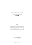
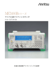
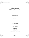
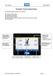
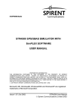
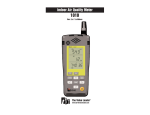
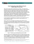
QuickSyn
MICROWAVE FREQUENCY SYNTHESIZER
Calibration Software
User’s Manual
DOC. NO. 5580515-01 | REV. B | ECN 001540
National Instruments | 4600 Patrick Henry Drive, Santa Clara CA 95054 | 408-610-6810 | ni-microwavecomponents.com
Notices
© 2014 National Instruments
Warranty
No part of this manual may be copied,
duplicated, or reproduced in any form
or by any means (including electronic
storage and retrieval or translation
into a foreign language) without prior
agreement and written consent from
National Instruments as governed
by United States and international
copyright laws.
National Instruments warrants this
product to be free from defects in material and workmanship for one year
from the date of delivery. Damage
due to accident, abuse, or improper
signal level is not covered by the
warranty. Removal, defacement, or
alteration of any serial or inspection
label, marking, or seal may void the
warranty. National Instruments will
repair or replace, at its option, any
components of this product which
prove to be defective during the warranty period, provided the entire unit
is returned to National Instruments
or an authorized service facility.
In-warranty units will be returned
freight prepaid; out-of-warranty units
will be returned freight COLLECT.
No warranty other than the above is
expressed or implied.
National Instruments
4600 Patrick Henry Drive
Santa Clara CA 95054
Software Copyright
Original National Instruments
software may be distributed without
consent from National Instruments
only if all software and associated
files are included in the distribution
and remain unmodified.
Safety Notices
CAUTION
A CAUTION notice denotes a
hazard. It calls attention to an
operating procedure, practice,
or the like that, if not correctly performed or adhered to,
could result in damage to the
product or loss of important
data. Do not proceed beyond
a CAUTION notice until the
indicated conditions are fully
understood and met.
WARNING
A WARNING notice defines
a hazard. It calls attention to
an operating procedure or
practice that if not correctly
followed or adhered to, could
result in either personal injury or death. Do not proceed
beyond a WARNING notice
until the indicated conditions
are fully understood and
met.
Calibration SoftwareUser’s Manual
Introducing Calibration Software for the QuickSyn
Frequency Synthesizer
You can calibrate the QuickSyn Frequency Synthesizer with
the QuickSyn Soft Front Panel for Calibration. There are two
calibration modes—power calibration and internal oscillator
calibration. Both may be performed in a laboratory environment
(which is equipped with the proper equipment) without the need to
send the unit back to the factory for periodic calibration.
It is recommended that this User’s Manual be read carefully and
completely.
In this document . . .
The scope of this document is to describe how to calibrate the
QuickSyn Frequency Synthesizer using the QuickSyn Soft Front
Panel for Calibration.
Step 1. Install QuickSyn Soft Front Panel for Calibration
Step 2. Review Software Front Panels
Step 3. Perform Power Calibration
Step 4. Perform Reference Calibration
NOTE
We recently changed the branding of the QuickSyn product line by replacing the
Phase Matrix logo with the NI logo. In some cases, as we deplete out stock, you may
observe that the Phase Matrix logo remains on packaging, software, manuals, and the
unit itself. Other than the mere change of the logo, QuickSyn products continue to
employ the same revolutionary phase-refining technology that enables blazing-fast
switching speeds and very low-noise and spurious performance in the same compact
package.
QuickSyn Frequency Synthesizer Calibration
3 of 30
Calibration Software User’s Manual
Step 1. Install QuickSyn Soft Front Panel for Calibration
NOTE
The QuickSyn USB device driver (available online at ni-microwavecomponents.com)
must be installed before installing the QuickSyn Soft Front Panel for Calibration.
NOTE
The QuickSyn Soft Front Panel for Calibration will run on a PC using Windows
XP, Windows Vista, and Windows 7. The example shown here was performed on a
Windows 7 PC.
1 Download the latest available QuickSyn Soft Front Panel for
Calibration from the NI Microwave Components website
Software is available at ni-microwavecomponents.com
2 Start the installation process by selecting Start > Run >
Browse, navigate to the “setup.exe” file, and select Open to
start the installation wizard.
An installer initialization screen similar to the one shown in
Figure 1 is displayed and when finished will provide a dialog box as
shown in Figure 2.
Figure 1 Example of Starting the Soft Fron Panel Installation Wizard
4 of 30
QuickSyn Frequency Synthesizer Calibration
Calibration SoftwareUser’s Manual
Figure 2 Example of Selecting Destination Directory for Executables
4 Enter the destination directory for the Soft Front Panel
executables or browse to a destination directory by selecting the
Browse button (See Figure 2).
5 Once the file path has been entered, select Next to continue to
the Software License Agreement.
QuickSyn Frequency Synthesizer Calibration
5 of 30
Calibration Software User’s Manual
Figure 3 Example of Software License Agreement
6 Carefully read through the Software License Agreement (see
Figure 3).
•
If you agree to the terms of the software license agreement,
select “I accept the License Agreement” and select Next to
continue.
•
If you do not agree, you will not be able to install the software.
A screen similar to the one shown in Figure 4 will appear to show
the progress of files being installed.
Figure 4 Example of Files Being Copied
6 of 30
QuickSyn Frequency Synthesizer Calibration
Calibration SoftwareUser’s Manual
7Select Finish (as shown in Figure 5) to complete the Soft Front
Panel installation. Reboot the computer if prompted to do so.
Figure 5 Example of Completing Soft Front Panel Installation Wizard
QuickSyn Frequency Synthesizer Calibration
7 of 30
Calibration Software User’s Manual
Step 2. Review Software Front Panels
Step 2-1 Launch QuickSyn Soft Front Panel for Calibration
1 Use the shortcut icon
that was placed on the computer’s
desktop during installation to launch the QuickSyn Soft Front
Panel for Calibration.
The “Locate QuickSyn Device” dialog box will appear (see Figure 6).
Figure 6 Example of “Locate QuickSyn Device” dialog box
2 Enter a name for the QuickSyn module. The default name is
“USBComPort.” The name that is entered here will appear
at the top of the Main Control panel, which will help the user
differentiate between multiple QuickSyn units attached to the
computer.
3 Select the com port to which the QuickSyn module is connected
and choose OK.
8 of 30
QuickSyn Frequency Synthesizer Calibration
Calibration SoftwareUser’s Manual
Step 2-2 Review Power Calibration Panel
The QuickSyn Soft Front Panel for Calibration contains two tabs
near the upper-left corner (see Figure 7). These tabs enable the user
to calibrate the synthesizer’s RF output power (Power Cal tab) and
its internal reference (Ref. Cal tab).
Stop Button  This button is used to stop the Soft Front Panel for
Calibration from reading and writing to the synthesizer; it halts the
program and is the preferred way to exit the program.
Model Number, Serial Number, Options, Firmware Ver,
Calibration Date  The information area, located above the tabs
reveals the synthesizer’s model number, serial number, date of last
calibration, currently installed options, and firmware version. This
information cannot be changed.
Figure 7 Power Calibration Panel
QuickSyn Frequency Synthesizer Calibration
9 of 30
Calibration Software User’s Manual
Power Meter  This selection box is used to specify the GPIB
address for the power meter connected to the synthesizer. To enter
a value in this box, select the arrow on the left side of the box and
select the applicable value.
Path Cal File/Update  The name of the path calibration file is
indicated in this field and cannot be changed. The Update button to
the left of the Path Cal File field is used to create the necessary path
calibration file.
Calibration File Name  This field indicates the name of the file
that contains graph data. The path to the file is revealed in the box
on the left side of the Calibration File Name field.
Calibration Mode Auto On  The Calibration Mode Auto On
button, when pressed, enables automatic sequencing of calibration
steps. The button is illuminated when on.
Warm Up Time  This entry box is used to specify the period of
time the calibration process will delay before beginning a power
sweep. To enter a value, highlight the number in the entry box and
enter a value or use the up/down arrow on the left side of the box.
After a value is entered and the Max/Min Pwr Sweep button pressed
a Delay dialog box will appear (as shown in Figure 8) and will
count down the time delay. To abort the delay, select Bypass on the
Delay dialog box, and the calibration will proceed.
Figure 8 Delay Dialog Box
Max/Min Pwr Sweep  This button, when pressed, executes
a power sweep, which is the first step in a sequence of steps
to calibrate the synthesizer’s output power. When this step is
complete, the indicator to the left of the button will illuminate.
10 of 30
QuickSyn Frequency Synthesizer Calibration
Calibration SoftwareUser’s Manual
Start Cal  This button, when pressed, starts the power calibration
step. When the step is complete, the indicator to the left of the
button will illuminate.
Write Cal to UUT  This button, when pressed, stores calibration
data (when it is available) into the synthesizer’s volatile memory.
The current calibration data stored in the synthesizer’s permanent
memory will not be overwritten. When the step is complete, the
indicator to the left of the button will illuminate. “UUT” stands for
unit under test.
Verify Cal  This button, when pressed, measures each calibrated
frequency and displays the measured power in the Power vs.
Frequency graph. Power is verified every 5 dB. When the step is
complete, the indicator to the left of the button will illuminate.
Store in Flash  This button, when pressed, stores the calibration
data into the permanent memory of the synthesizer. The synthesizer
will recognize the data as the default calibration. When the step
is complete, the indicator to the left of the button will illuminate.
Note that this step is not automatic and must be executed manually.
Abort  This button, when pressed, halts action associated with a
step in process. A step may be aborted at anytime.
Check Max (+15)  The Check Max selection bar allows the
user to select among three options for checking the minimum and
maximum values of the power sweep, Check Min (-25) and Max
(+15), Check Min (-25), and Check Max (+15).
•
When Check MIN (-25) and Max (+15) is selected, both the
minimum and maximum achievable power levels will be
displayed on the graph.
•
When Check MIN (-25) is selected, only the mimimum
achievable power level will be displayed on the graph.
•
When Check Max (+15) is selected, only the maximum
achievalbe power level will be displayed on the graph.
QuickSyn Frequency Synthesizer Calibration
11 of 30
Calibration Software User’s Manual
Load Cal File  This button, when pressed, launches a dialog box
similar to the one shown in Figure 9 and allows the user to retrieve
a previously created calibration file instead of executing the Start
Cal step. When the file is loaded, the indicator to the left of the
button will illuminate.
Figure 9 Example Load Cal File Dialog Box
Fixed Power Option  This selection button is used to select fixed
power output rather than variable power output. To choose fixed
power, select the checkbox and enter a value in the entry box to the
right of the checkbox. To enter a value, highlight the number in the
entry box and enter a value or use the up/down arrow on the left
side of the box.
Power Control  The Power Control bar allows the user to select
among three different verification options, Power Control, Fixed
Power, User Defined.
12 of 30
•
When Power Control is selected, verification of power will
occur at 5 dB intervals across the entire specified power range
of the synthesizer.
•
When Fixed Power is selected, control of power is disabled and
the power is set to the specified fixed power. This choice can
only be used with previously written calibration data obtained
from selecting the Fixed Power Option.
QuickSyn Frequency Synthesizer Calibration
Calibration SoftwareUser’s Manual
•
When User Defined is selected and the Define button pressed, a
dialog box, similar to the one shown in Figure 10, appears and
allows the user to choose the frequency range, power range,
and step size desired for verification. To enter a value within
the dialog box, highlight the default number in each of the entry
boxes and enter a value or use the up/down arrow on the left
side of the boxes. Press OK to execute verification. The DAC
(V) button is used for troubleshooting and is not intended for
normal operation.
Figure 10 Example User Defined Verify Settings Dialog Box
Define  This button becomes available when the User Defined
option is chosen. When pressed, the dialog box shown in Figure 10
appears.
Step Progress  The Step Progress bar graphically reveals the
progress during each step.
Step Details  This area shows various details as the power
calibration progresses.
Frequency (Hz)  This read-only field shows the frequency
measured in Hertz as the calibration progresses.
Power Level  This read-only field shows the current power level
measured as the calibration progresses.
QuickSyn Frequency Synthesizer Calibration
13 of 30
Calibration Software User’s Manual
PCC  This read-only field displays the Power Cal constant as it is
updated during calibration.
DAC-A  This read-only field shows the DAC-A voltage as it is
updated during calibration.
Power vs. Frequency Graph  The graph displays RF power vs.
frequency during the process of creating a calibration path file and
during several of the calibration steps. The graph data represents
the power measured at the RF output connector of the QuickSyn
synthesizer.
•
When creating a Path Cal File, initially the graph reveals the
direct output power across the synthesizer’s entire frequency
range at a fixed power of +10 dBm. After the calibration
path (a 6 dB attenuator pad) is attached, the graph shows
the measured calibration path loss across the synthesizer’s
frequency range.
•
When the Max/Min Pwr Sweep button is selected, the graph
displays RF power measured between a specified minimum and
maximum range at each frequency step over the synthesizer’s
entire frequency range.
•
When the Start Cal button is selected, the graph reveals
calibration frequencies and power control values.
•
When the Verify Cal button is selected, the graph shows the
measured and verified power at every 5 dB interval across the
synthesizer’s entire frequency range.
Save Data to File  This button, when selected, allows graph data
to be saved in a tab-delimited file.
14 of 30
QuickSyn Frequency Synthesizer Calibration
Calibration SoftwareUser’s Manual
Step 2-3 Review Reference Calibration Panel
The reference calibration panel shown in Figure 11 is accessible
by selecting the Ref. Cal tab located near the upper-left corner
of the QuickSyn Soft Front Panel for Calibration. The reference
calibration panel allows the user to calibrate the synthesizer’s
internal reference. The synthesizer’s ovenized crystal oscillator
(OCXO) will be tuned to the synthesizer’s specification for a
10 MHz reference standard.
Frequency Counter  The Frequency Counter selection box
allows the user to specify the GPIB address to which an external
frequency counter is connected.
Model  The Model selection box enables the user to identify
the frequency counter connected to the synthesizer. The
user may choose from three models, an Anritsu MF2412B, a
Pendulum CNT-90, or a Phase Matrix 346A.
Figure 11 Reference Calibration Panel
QuickSyn Frequency Synthesizer Calibration
15 of 30
Calibration Software User’s Manual
Start Ref Cal  This button, when pressed, initiates the calibration
of the synthesizer’s OCXO internal reference and is the first of
the two calibration steps to calibrate the internal reference. When
this step is complete, the indicator to the left of the button will
illuminate.
Write Ref Cal to UUT  This button, when pressed, stores the
reference calibration value into the synthesizer’s permanent
memory and will overwrite the previous value. In addition, the
date of calibration will be updated. When the step is complete, the
indicator to the left of the button will illuminate.
Abort  This button, when pressed, halts action associated with a
step in process. A step may be aborted at anytime.
Ref Warm Up Time  This entry box is used to specify the period
of time the calibration process will delay before initiating. To enter
a value, highlight the number in the entry box and enter the desired
value or use the up/down arrow on the left side of the box. After the
value is entered and the Start Ref Cal button pressed, a Delay dialog
box will appear (as shown in Figure 8) and will count down the
delay. To abort the delay, select Bypass on the Delay dialog box,
and the calibration will proceed.
Ref Voltage  This read-only field shows the reference voltage as
the calibration progresses.
Step  This read-only field shows the voltage step of the reference
DAC voltage as the calibration progresses.
Current Ref Voltage  This read-only field displays the current
reference DAC voltage as the calibration progresses.
Frequency (Hz)  This read-only field shows the frequency that is
read back from the frequency counter as the calibration progresses.
16 of 30
QuickSyn Frequency Synthesizer Calibration
Calibration SoftwareUser’s Manual
Step 3. Perform Power Calibration
Step 3-1 Confirm Equipment
Ensure that the items listed in Table 1 are present before starting
the power calibration process.
Table 1 Power Calibration Requirements
Unit to be Calibrated
• FSW-0010 or FSW-0020 QuickSyn synthesizer
Equipment
•
Agilent E4418B power meter (or exact SCPI-command
equivalent)
•
Agilent E4413A power sensor (or equivalent)
•
Aeroflex 26AH-06 attenuator (or equivalent)*
• 12-volt power supply
Software
• QuickSyn Soft Front Panel for Calibration
Computer
• PC with a Windows® XP or higher operating system and
GPIB enabled
* The 6 dB attenuator is referred to as “Calibration Path” in this
document.
QuickSyn Frequency Synthesizer Calibration
17 of 30
Calibration Software User’s Manual
Step 3-2 Create Path Caibration File
A Path Calibration File must be created before starting the
power calibration. The file will contain data from a direct power
measurement and a calibration path loss measurement. A Path
Calibration File example is shown in Figure 12.
Figure 12 Example Path Calibration File
NOTE
18 of 30
If a path calibration has been performed previously, it is not necessary to calibrate the
path again unless the path has been changed or affected such that the integrity of the
path is compromised.
QuickSyn Frequency Synthesizer Calibration
Calibration SoftwareUser’s Manual
Refer to Figure 13 to setup the equipment for the direct power
measurement.
Figure 13 Equipment Setup for Direct Power Measurement
1. Connect the PC to the USB connector of the synthesizer.
2. Ensure that the power supply is turned off and then connect
the power supply to the synthesizer.
WARNING
Voltages less than +12 V at the synthesizer connector may result in malfunction,
and voltages in excess of +15 V may damage the synthesizer.
3. Attach the power sensor to the power meter.
4. Do not connect the power sensor to the synthesizer’s RF OUT
until prompted to do so by the QuickSyn Soft Front Panel for
Calibration.
5. Launch the QuickSyn Soft Front Panel for Calibration
software (refer to instructions in Section/Step 2-1 if
necessary).
QuickSyn Frequency Synthesizer Calibration
19 of 30
Calibration Software User’s Manual
6. Select the Update button on the Power Cal tab.
A dialog box similar to the one shown in Figure 14 will appear to
prompt the user to connect the power sensor to the synthesizer’s RF
output connector.
Figure 14 Example Connect Power Sensor Dialog Box
7. Connect the power sensor from the power meter to the
synthesizer’s RF OUT and then select OK.
The Power vs. Frequency graph (see Figure 15) will display the
fixed output power as it is measured across the frequency range of
the synthesizer at +10 dBm.
Figure 15 Direct Power Measurement
20 of 30
QuickSyn Frequency Synthesizer Calibration
Calibration SoftwareUser’s Manual
When the direct power measurement is complete, a dialog box
(similar to the one shown in Figure 16) will appear to prompt the
user to insert the 6 dB pad or calibration path.
Figure 16 Example Connect Calibration Path Dialog Box
8. Refer to Figure 17 and connect the calibration path input
to the synthesizer’s RF OUT and the power sensor to the
calibration path’s output. Press OK to proceed.
Figure 17 Equipment Setup for Calibration Path Loss Measurement
QuickSyn Frequency Synthesizer Calibration
21 of 30
Calibration Software User’s Manual
The Power vs. Frequency graph (see Figure 18) will display
the calibration path loss measurement at each frequency. When
the calibration path loss measurement is complete across all
of the frequencies, the loss is computed and stored in the Path
Calibration File.
Figure 18 Calibration Path Loss Measurement
22 of 30
QuickSyn Frequency Synthesizer Calibration
Calibration SoftwareUser’s Manual
Step 3-3 Perform Power Calibration
There are five calibration steps located on the Power Cal tab of
the QuickSyn Soft Front Panel for Calibration: Min/Max Power
Sweep, Start Cal, Write Cal to UUT, Verify Cal, and Store in
Flash. Each step has a corresponding button on the panel (see
Section/Step 2-2).
If the equipment is setup from the previous step (Step 3-2 Create
Path Calibration File), proceed to instruction step five below, and
refer to Figure 19.
Figure 19 Equipment Setup for Power Calibration
1. Connect the PC to the USB connector of the synthesizer.
2. Ensure the power supply is truned off, and then connect the
power supply to the synthesizer.
WARNING
Voltages less than +12 V at the synthesizer connector may result in malfunction,
and voltages in excess of +15 V may damage the synthesizer.
QuickSyn Frequency Synthesizer Calibration
23 of 30
Calibration Software User’s Manual
3. Attach the power sensor to the power meter.
4. Connect the calibration path input to the Synthesizer’s RF
OUT and the power sensor to the calibration path’ output.
5. Connect the power meter to the GPIB-capable PC with a
GPIB cable.
6. From the Power Cal tab of QuickSyn Soft Front Panel for
Calibration, select the GPIB address of the connected power
meter.
Max/Min Pwr Sweep
The option of imposing a time delay for the synthesizer to warm
up can be set by entering a value in the Warm Up Time entry box.
Also, the option of an automatic execution of calibration steps
can be chosen by pressing the Auto On button. The sequence of
calibration steps will proceed automatically through to the Verify
Cal step when the Max/Min Pwr Sweep button is pressed with the
Auto On is set. Note, however, that the Store in Flash step is not
automatic and must be executed manually. The steps described
from this point forward are based on a manual power calibration
(i.e., without Auto On).
NOTE
Calibration frequencies and power levels are set automatically based on the QuickSyn
synthesizer model, FSW-0010 or FSW-0020.
7. Choose a minimum-maximum power sweep parameter by
selecting the Check Max (+15) selection bar.
8. Press the Max/Min Pwr Sweep button to execute the power
sweep.
24 of 30
QuickSyn Frequency Synthesizer Calibration
Calibration SoftwareUser’s Manual
As the RF power is measured, results will be displayed on the
Power vs. Frequency graph (see Figure 20). The power sweep
will take up to 10 minutes. The indicator to the right of the Max/
Min Pwr Sweep button will illuminate when the step is finished.
Figure 20 Example Power Sweep Graph
Start Cal
9. Press the Start Cal button to execute the calibration step.
Each point is measured and displayed on the Power vs. Frequency
graph (see Figure 21). The data is stored in a file named in the
Calibration File Name box. The file can be loaded at a later date
by using the Load Cal File option. The calibration step will take
from 30 to 60 minutes. The indicator to the right of the Max/Min
Pwr Sweep button will illuminate when the step is finished.
QuickSyn Frequency Synthesizer Calibration
25 of 30
Calibration Software User’s Manual
Figure 21 Power vs. Frequency Graph
Load Cal File
If a previously created calibration file is available, it can be loaded
by selecting the Load Cal File button instead of executing the
Start Cal step. When a file is loaded, the indicator to the right of
the Load Cal File button will illuminate.
Write Cal to UUT
The calibration data generated in the previous step must be stored
in order to be verified; therefore, the Write Cal to UUT step must be
executed. The choice between fixed and variable power is available
and must be made before starting the write step. To choose fixed
power, select the Fixed Power Option box and enter a power value;
otherwise, the choice of variable power is the default setting.
10. Press the Write Cal to UUT button.
CAUTION
If the synthesizer is power cycled or turned off and on at the end of the Write Cal to
UUT step, the data will not be retained, and previous data from permanent memory
will be reloaded.
This step will take up to 5 minutes. The indicator to the right of the
Write Cal to UUT button will illuminate when the step is finished.
26 of 30
QuickSyn Frequency Synthesizer Calibration
Calibration SoftwareUser’s Manual
Figure 22 Example Verification of Calibration Data
Verify Cal
The user may select among three options to verify the calibration
data by selecting the Power Control selection bar. The three options
are Power Control, Fixed Power, and User Defined. Refer to Section/Step 2-2 for an explanation of each of these options.
11. After selecting a verification option, press the Verify Cal button
to start verification of the data.
As each calibrated frequency is measured, the power data is displayed
on the Power vs. Frequency Graph as shown in Figure 22. It is
normal for a step to appear from +10 dBm to +15 dBm at 500 MHz.
Store in Flash
The final step to complete the power calibration is the Store in Flash step,
which will store the calibration data into the synthesizer’s memory.
12. Review the calibration data to ensure its validity, and then press
the Store in Flash button.
CAUTION
The Store in Flash function will overwrite previous calibration data that may be
stored in permanent memory; therefore, verify calibration data before executing the
Store in Flash step.
When this step is complete, the indicator next to the Store in Flash
button will illuminate.
QuickSyn Frequency Synthesizer Calibration
27 of 30
Calibration Software User’s Manual
Step 4. Perform Reference Calibration
Step 4-1 Confirm Equipment
Ensure that the items listed in Table 2 are present before starting
the reference calibration process.
Table 2 Reference Calibration Requirements
Unit to be Calibrated
• FSW-0010 or FSW-0020 QuickSyn synthesizer
Equipment
•
10 MHz frequency standard
•
Frequency Counter (one listed here or an exact SCPI
command equivalent)
•
•
Pendulum CNT-90
•
Anritsu MF2412B
•
Phase Matrix 346A
12-volt power supply
Software
• QuickSyn Soft Front Panel for Calibration
Computer
• PC with a Windows® XP or higher operating system and
GPIB enabled.
28 of 30
QuickSyn Frequency Synthesizer Calibration
Calibration SoftwareUser’s Manual
Step 4-2 Perform Reference Calibration
There are two calibration steps located on the Ref. Cal tab of the
QuickSyn Soft Front Panel for Calibration: Start Ref Cal and
Write Ref Cal to UUT. Each step has a corresponding button on
the panel (see Section/Step 2-2).
Refer to Figure 23 to setup the equipment for the reference
calibration.
Figure 23 Equipment Setup for Reference Calibration
1. Connect the PC to the USB connector of the
synthesizer.
2. Ensure that the power supply is turned off, then connect the
power supply to the synthesizer.
WARNING
Voltages less than +12 V at the synthesizer connector may result in malfunction,
and voltages in excess of +15 V may damage the synthesizer.
QuickSyn Frequency Synthesizer Calibration
29 of 30
Calibration Software User’s Manual
3. Connect the frequency counter reference input to the
10 MHz reference standard.
4. Connect the synthesizer’s RF OUT to the frequency counter’s
RF input.
5. Connect the frequency counter to the GPIB-capable PC with a
GPIB cable as shown in Figure 23.
6. Launch the QuickSyn Soft Front Panel for Calibration
software (refer to instructions in Section/Step 2-1 if
necessary).
7. From the Ref. Cal tab, select the GPIB address of the
connected frequency counter and identify the model in the
Model selection box.
Start Ref Cal
8. Press the Start Ref Cal button to start the reference
calibration process.
The tuning voltage of the OCXO will be adjusted multiple times
until the frequency is within ±20 Hz @ 10 GHz. During this step,
the calibration value will be stored in volatile memory and will not
be retained if the synthesizer’s power is cycled or turned off and on.
The indicator to the right of the Start Ref Cal button will illuminate
when the step is finished.
Write Ref Cal to UUT
Press the Write Ref Cal to UUT to store the reference calibration
value to the synthesizer’s permanent memory.
9. Power cycle (i.e., turn off and on) the synthesizer to load the
new value.
30 of 30
QuickSyn Frequency Synthesizer Calibration