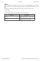
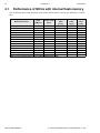
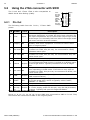
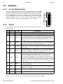
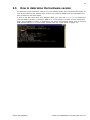
1
Flasher ARM
User guide of the stand-alone
JTAG/SWD programmer for ARM Cores
Manual Rev. 24
Date: October 19, 2012
Document: UM08007
A product of SEGGER Microcontroller GmbH & Co. KG
www.segger.com
2
Disclaimer
Specifications written in this document are believed to be accurate, but are not guaranteed to be entirely free of error. The information in this manual is subject to
change for functional or performance improvements without notice. Please make sure
your manual is the latest edition. While the information herein is assumed to be
accurate, SEGGER Microcontroller GmbH & Co. KG (the manufacturer) assumes no
responsibility for any errors or omissions. The manufacturer makes and you receive
no warranties or conditions, express, implied, statutory or in any communication with
you. The manufacturer specifically disclaims any implied warranty of merchantability
or fitness for a particular purpose.
Copyright notice
You may not extract portions of this manual or modify the PDF file in any way without
the prior written permission of the manufacturer. The software described in this document is furnished under a license and may only be used or copied in accordance
with the terms of such a license.
© 2012 SEGGER Microcontroller GmbH & Co. KG, Hilden / Germany
Trademarks
Names mentioned in this manual may be trademarks of their respective companies.
Brand and product names are trademarks or registered trademarks of their respective holders.
Contact address
SEGGER Microcontroller GmbH & Co. KG
In den Weiden 11
D-40721 Hilden
Germany
Tel.+49 2103-2878-0
Fax.+49 2103-2878-28
Email: [email protected]
Internet: http://www.segger.com
Revisions
This manual describes the Flasher ARM device.
For further information on topics or routines not yet specified, please contact us.
Revision
Date
By
23
121019
EL
23
120626
AG
22
110927
EL
21
110927
AG
20
110216
AG
19
101213
KN
Flasher ARM (UM08007)
Explanation
Chapter "Working with Flasher ARM"
* Section "LED status indicator" updated.
Chapter "Working with Flasher ARM"
* Section "Serial number programming" updated.
Chapter "Working with Flasher ARM"
* Section "Serial number programming" added.
Chapter "Working with Flasher ARM"
* Section "Setting up the IP interface" added.
Chapter "Working with Flasher ARM"
* Section "Supported microcontrollers" updated.
* Section "Support of external flashes" updated.
Chapter "Performance"
* Section "Performance of MCUs with internal
flash memory" updated
© 2004-2012 SEGGER Microcontroller GmbH & Co. KG
3
Revision
Date
By
18
090727
AG
17
090616
AG
16
090519
AG
15
090515
AG
14
090508
AG
13
090506
AG
12
090122
AG
11
090114
AG
10
081211
KN
9
081113
AG
8
081105
AG
7
081031
AG
6
081030
AG
5
080929
AG
4
080926
AG
3
080912
AG
2
1
0
080827
080820
071204
AG
AG
AG
Flasher ARM (UM08007)
Explanation
Chapter "Working with Flasher ARM"
* Section "Supported microcontrollers" updated.
* Section "JTAG speed" removed.
* Section "target interfaces" added.
Chapter "Remote control"
* Section "Overview" updated.
Chapter "Performance"
* Section "Performance of MCUs with internal
flash memory" updated.
Chapter "Working with Flasher ARM"
* Section "Multiple file support" added.
Chapter "Remote control"
* Section "ASCII command interface" spelling
corrections.
Chapter "Remote control"
* Section "ASCII command interface" updated.
Chapter "Remote control"
* Section "ASCII command interface" updated.
Chapter "Remote control"
* Section "ASCII command interface" updated.
Chapter "Working with Flasher ARM"
* Section "Supported microcontrollers" updated.
Chapter "Working with Flasher ARM"
* Section "LED status indicators" upadted.
Several corrections.
Chapter "Working with Flasher ARM"
* Section "Supported microcontrollers" updated.
Chapter "Remote control"
*Section "ASCII command interface" updated.
Chapter "Remote control"
* Section "Handshake control" updated.
* Section "ASCII command interface" updated.
Chapter "Working with Flasher ARM"
* Section "Supported microcontrollers" corrected.
Chapter "Remote control"
* Section "ASCII command interface" updated.
Chapter "Working with Flasher ARM"
* Section "Supported microcontrollers" updated.
Chapter "Working with Flasher ARM"
* Section "MSD mode" updated.
Chapter "Support and FAQs"
* Section "Contacting support" updated.
Chapter "Remote control"
* Section "ASCII command interface" updated.
Chapter "Working with Flasher ARM"
* Section "Supported microcontrollers" updated.
Chapter "Remote control" added.
Chapter "Background information"
* Section "Flasher ARM firmware" removed.
Several corrections.
Several improvements/corrections.
Initial version.
© 2004-2012 SEGGER Microcontroller GmbH & Co. KG
4
Flasher ARM (UM08007)
© 2004-2012 SEGGER Microcontroller GmbH & Co. KG
5
About this document
This document describes the Flasher ARM. It provides an overview over the major
features of the Flasher ARM, gives you some background information about JTAG,
ARM general and describes Flasher ARM related software packages available from
Segger. Finally, the chapter Support and FAQs on page 53 helps to troubleshoot common problems.
Typographic conventions
This manual uses the following typographic conventions:
Style
Used for
Body
Body text.
Keyword
Text that you enter at the command-prompt or that appears on the
display (that is system functions, file- or pathnames).
Reference
Reference to chapters, tables and figures or other documents.
GUIElement
Buttons, dialog boxes, menu names, menu commands.
Table 1.1: Typographic conventions
Flasher ARM (UM08007)
© 2004-2012 SEGGER Microcontroller GmbH & Co. KG
6
SEGGER Microcontroller GmbH & Co. KG develops
and distributes software development tools and ANSI
C software components (middleware) for embedded
systems in several industries such as telecom, medical technology, consumer electronics, automotive
industry and industrial automation.
SEGGER’s intention is to cut software developmenttime for embedded applications by offering compact flexible and easy to use middleware,
allowing developers to concentrate on their application.
Our most popular products are emWin, a universal graphic software package for embedded applications, and embOS, a small yet efficient real-time kernel. emWin, written
entirely in ANSI C, can easily be used on any CPU and most any display. It is complemented by the available PC tools: Bitmap Converter, Font Converter, Simulator and
Viewer. embOS supports most 8/16/32-bit CPUs. Its small memory footprint makes it
suitable for single-chip applications.
Apart from its main focus on software tools, SEGGER develops and produces programming
tools for flash microcontrollers, as well as J-Link, a JTAG emulator to assist in development, debugging and production, which has rapidly become the industry standard for
debug access to ARM cores.
Corporate Office:
http://www.segger.com
EMBEDDED SOFTWARE
(Middleware)
United States Office:
http://www.segger-us.com
SEGGER TOOLS
emWin
Flasher
Graphics software and GUI
emWin is designed to provide an efficient, processor- and display controller-independent graphical user
interface (GUI) for any application that
operates with a graphical display.
Starterkits, eval- and trial-versions are
available.
Flash programmer
Flash Programming tool primarily for microcontrollers.
J-Link
embOS
JTAG emulator with trace
USB driven JTAG interface for ARM cores with
Trace memory. supporting the ARM ETM (Embedded Trace Macrocell).
Real Time Operating System
embOS is an RTOS designed to offer
the benefits of a complete multitasking
system for hard real time applications
with minimal resources. The profiling
PC tool embOSView is included.
emFile
JTAG emulator for ARM cores
USB driven JTAG interface for ARM cores.
J-Trace
J-Link / J-Trace Related Software
Add-on software to be used with SEGGER’s industry standard JTAG emulator, this includes flash
programming software and flash breakpoints.
File system
emFile is an embedded file system with
FAT12, FAT16 and FAT32 support.
emFile has been optimized for minimum memory consumption in RAM and
ROM while maintaining high speed.
Various Device drivers, e.g. for NAND
and NOR flashes, SD/MMC and CompactFlash cards, are available.
emUSB
USB device stack
A USB stack designed to work on any
embedded system with a USB client
controller. Bulk communication and
most standard device classes are supported.
Flasher ARM (UM08007)
© 2004-2012 SEGGER Microcontroller GmbH & Co. KG
7
Table of Contents
1 Introduction ......................................................................................................................9
1.1
1.1.1
1.1.2
1.2
1.2.1
1.2.2
Flasher ARM overview .............................................................................. 10
Features of Flasher ARM ........................................................................... 10
Working environment ............................................................................... 10
Specifications.......................................................................................... 11
Specifications for Flasher ARM ................................................................... 11
Flasher ARM Download speed .................................................................... 11
2 Working with Flasher ARM ............................................................................................13
2.1
2.1.1
2.2
2.2.1
2.2.2
2.2.3
2.3
2.4
2.4.1
2.4.2
2.4.3
2.4.4
2.4.5
2.4.6
2.5
2.6
2.7
2.8
Setting up the IP interface ........................................................................ 14
Connecting the first time .......................................................................... 14
Operating modes ..................................................................................... 15
J-Link mode ............................................................................................ 15
Stand-alone mode ................................................................................... 19
MSD mode.............................................................................................. 19
Multiple File Support ................................................................................ 21
Serial number programming...................................................................... 22
Serial number settings ............................................................................. 22
Serial number file .................................................................................... 23
Serial number list file ............................................................................... 23
Programming process............................................................................... 24
Downloading serial number files to Flasher ARM........................................... 25
Sample setup.......................................................................................... 25
Target interfaces ..................................................................................... 27
Supported microcontrollers ....................................................................... 28
Support of external flashes ....................................................................... 29
Supported ARM Cores .............................................................................. 30
3 Remote control...............................................................................................................31
3.1
3.2
3.3
3.3.1
3.3.2
3.3.3
3.3.4
3.3.5
Overview ................................................................................................ 32
Handshake control ................................................................................... 33
ASCII command interface ......................................................................... 34
Introduction............................................................................................ 34
General command and reply message format .............................................. 34
Communication port settings..................................................................... 34
Commands to Flasher............................................................................... 34
Reply from Flasher ARM............................................................................ 38
4 Performance ..................................................................................................................41
4.1
Performance of MCUs with internal flash memory ......................................... 42
5 Hardware .......................................................................................................................43
5.1
5.1.1
5.1.2
5.1.3
5.2
5.2.1
5.3
JTAG Connector....................................................................................... 44
Pinout .................................................................................................... 44
Target board design for JTAG .................................................................... 45
Target power supply ................................................................................ 45
Using the JTAG connector with SWD........................................................... 46
Pin Out................................................................................................... 46
RESET, nTRST ......................................................................................... 47
Flasher ARM (UM08007)
© 2004-2012 SEGGER Microcontroller GmbH & Co. KG
8
5.4
5.4.1
5.4.2
5.5
Adapters ................................................................................................ 48
J-Link JTAG Isolator................................................................................. 48
Pinout.................................................................................................... 48
How to determine the hardware version ..................................................... 49
6 Background information .................................................................................................51
6.1
6.1.1
6.1.2
6.1.3
Flash programming ................................................................................. 52
How does flash programming via Flasher ARM work ?................................... 52
Data download to RAM ............................................................................. 52
Available options for flash programming ..................................................... 52
7 Support and FAQs .........................................................................................................53
7.1
7.2
Contacting support .................................................................................. 54
Frequently Asked Questions...................................................................... 55
8 Glossary.........................................................................................................................57
9 Literature and references...............................................................................................61
Flasher ARM (UM08007)
© 2004-2012 SEGGER Microcontroller GmbH & Co. KG
9
Chapter 1
Introduction
This chapter gives a short overview about the Flasher ARM.
Flasher ARM (UM08007)
© 2004-2012 SEGGER Microcontroller GmbH & Co. KG
10
CHAPTER 1
1.1
Introduction
Flasher ARM overview
Flasher ARM is a programming tool for microcontrollers with on-chip or external Flash
memory and ARM core. Flasher ARM is designed for programming flash targets with
the J-Flash software or stand-alone. In addition to that Flasher ARM has all of the JLink functionality. For more information about J-Link please refer to the J-Link / JTrace User Guide which can be downloaded at http://www.segger.com.
Flasher ARM connects via USB or via RS232 interface to a PC, running Microsoft Windows 2000, Windows XP, Windows 2003 or Windows Vista. Flasher ARM has a built-in
20-pin JTAG connector, which is compatible with the standard 20-pin connector
defined by ARM.
1.1.1
•
•
•
•
•
•
•
•
•
•
•
1.1.2
Features of Flasher ARM
Three boot modes: J-Link mode, stand-alone mode, MSD mode
Stand-alone JTAG programmer (Once set up, Flasher can be controlled without
the use of PC program)
No power supply required, powered through USB
Support for ARM7/ARM9/Cortex-M3
Supports internal and external flash devices
64 MB memory for storage of target program
Can be used as J-Link (JTAG emulator) with a download speed of up to 720
Kbytes/second
Programming speed between 30-300 Kbytes/second depending on target hardware
Serial in target programming supported
Data files can updated via J-Flash
Target interface: JTAG/SWD
Working environment
General
Flasher ARM can be operated from a PC with an appropriate software like J-Flash or
in stand-alone mode.
Host System
IBM PC/AT or compatible. CPU: 486 (or better) with at least 182MB of RAM, running
Microsoft Windows 2000, Windows XP, Windows 2003 or Windows Vista. It needs to
have an USB or RS232 interface available for communication with Flasher ARM.
Power supply
Flasher requires 5V DC, min. 100mA via USB connector. If USB is not connected, the
USB connector is used to power the device. Supply voltage is the same in this case.
Please avoid excess voltage.
Installing Flasher ARM PC-software J-Flash
The latest version of the J-Flash software, which is part of the J-Link software and
documentation package, can be downloaded from our website: http://www.segger.com. For more information about using J-Flash please refer to the J-Flash User
Guide which is also available for download on our website.
Flasher ARM (UM08007)
© 2004-2012 SEGGER Microcontroller GmbH & Co. KG
11
1.2
Specifications
1.2.1
Specifications for Flasher ARM
USB powered, 100mA for Flasher ARM.
500mA if target is powered by Flasher
ARM
Power Supply
USB Host Interface
RS232 Host Interface
Target Interface
Max. JTAG Transfer Rate
Supported Target Voltage
Target supply voltage
Target supply current
Operating Temperature
Storage Temperature
Relative Humidity (non-condensing)
Size (without cables)
Weight (without cables)
Supported OS
USB 2.0, full speed
RS232 9-pin
JTAG 20-pin (14-pin adapter available)
up to 12 MHz
1.8 - 5V
5V
Max. 400mA
+5°C ... +60°C
-20°C ... +65 °C
<90% rH
121mm x 66mm x 30mm
120g
Microsoft Windows 2000
Microsoft Windows XP
Microsoft Windows XP x64
Microsoft Windows 2003
Microsoft Windows 2003 x64
Microsoft Windows Vista
Microsoft Windows Vista x64
Table 1.1: Flasher ARM specifications
1.2.2
Flasher ARM Download speed
The following table lists Flasher ARM performance values (Kbytes/second) for writing
to memory (RAM) via the JTAG interface:
Hardware
Flasher ARM Rev. 1
ARM7
Memory download
720 Kbytes/s
(12MHz JTAG)
Table 1.2: Download speed differences between hardware revisions
Note:
The actual speed depends on various factors, such as JTAG, clock speed,
host CPU core etc.
Flasher ARM (UM08007)
© 2004-2012 SEGGER Microcontroller GmbH & Co. KG
12
Flasher ARM (UM08007)
CHAPTER 1
Introduction
© 2004-2012 SEGGER Microcontroller GmbH & Co. KG
13
Chapter 2
Working with Flasher ARM
This chapter describes functionality and how to use Flasher ARM.
Flasher ARM (UM08007)
© 2004-2012 SEGGER Microcontroller GmbH & Co. KG
14
CHAPTER 2
2.1
Working with Flasher ARM
Setting up the IP interface
Since hardware version 3 Flasher ARM comes with an additional Ethernet interface to
communicate with the host system. These Flashers also come with a built-in webserver which allows some basic setup of the emulator, e.g. configuring a default
gateway which allows using it even in large intranets.
2.1.1
Connecting the first time
When connecting Flasher the first time, it attempts to acquire an IP address via
DHCP. The recommended way for finding out which IP address has been assigned to
Flasher ARM is, to use the J-Link Configurator. The J-Link Configurator is a small GUIbased utility which shows a list of all emulator that are connected to the host PC via
USB and Ethernet. For more information about the J-Link Configurator, please refer
to UM08001, J-Link / J-Trace User Guide, chapter Setup, section J-Link Configurator.
The setup of the IP interface of Flasher ARM is the same as for other emulators of the
J-Link family. For more information about how to setup the IP interface of Flasher
ARM, please refer to UM08001, J-Link / J-Trace User Guide, chapter Setup, section
Setting up the IP interface. For more information about how to use Flasher ARM via
Ethernet or prepare Flasher ARM via Ethernet for stand-alone mode, please refer to
Operating modes on page 15.
Flasher ARM (UM08007)
© 2004-2012 SEGGER Microcontroller GmbH & Co. KG
15
2.2
Operating modes
Flasher ARM is able to boot in 3 different modes:
•
•
•
J-Link mode
Stand-alone mode
MSD (Mass storage device) mode
If Flasher ARM can enumerate on the USB port, Flasher ARM boots in "J-Link mode".
In this mode Flasher ARM can be used as a J-Link. When supply power is enabled and
Flasher ARM cannot enumerate, the "stand-alone mode" is started. In this mode
Flasher ARM can be used as a stand-alone flash programmer. When the Start/Stop
button is kept pressed when power supply is enabled, Flasher ARM boots in "MSD
mode". In this mode Flasher ARM boots as a mass storage device.
2.2.1
J-Link mode
When you want to use Flasher ARM for the first time you need to install the J-Link
ARM related software and documentation pack. After installation, connect Flasher
ARM to the host PC via USB. For more information about how to install the J-Link
ARM related software and documentation pack please refer to the J-Link / J-Trace
User Guide, chapter Setup which can be downloaded from http://www.segger.com/
download_jlink.html.
2.2.1.1 Connecting the target system
Power-on sequence
In general, Flasher ARM should be powered on before connecting it with the target
device. That means you should first connect Flasher ARM with the host system via
USB / RS232 and then connect Flasher ARM with the target device via JTAG. Poweron the device after you connected Flasher ARM to it. Flasher ARM will boot in "J-Link
mode".
Verifying target device connection with J-Link.exe
If the USB driver is working properly and your Flasher ARM is connected with the
host system, you may connect Flasher ARM to your target hardware. Then start the
J-Link command line tool JLink.exe, which should now display the normal Flasher
ARM related information and in addition to that it should report that it found a JTAG
target and the target’s core ID. The screenshot below shows the output of
JLink.exe.
2.2.1.2 Setting up Flasher ARM for stand-alone mode
In order to set up Flasher ARM for the stand-alone mode it needs to be configured
once using the J-Flash software. For more information about J-Flash, please refer to
the J-Flash User Guide. After starting J-Flash, open the appropriate J-Flash project
Flasher ARM (UM08007)
© 2004-2012 SEGGER Microcontroller GmbH & Co. KG
16
CHAPTER 2
Working with Flasher ARM
for the target Flasher ARM shall be configured for, by selecting File -> Open
Project. If J-Flash does not come with an appropriate sample project for the desired
hardware, a new project needs to be created by selecting File -> New Project.
After the approriate project has been opened / created, the data file which shall be
programmed needs to be loaded, by selecting File -> Open. After this J-Flash
should look like in the screenshot below.
Flasher ARM (UM08007)
© 2004-2012 SEGGER Microcontroller GmbH & Co. KG
17
Before downloading the configuration (project) and program data (data file) to
Flasher ARM, the connection type (USB/IP) needs to be selected in the project. These
settings are also saved on a per-project basis, so this also only needs to be setup
once per J-Flash project. The connection dialog is opened by clicking Options ->
Project settings -> General.
The connection dialog allows the user to select how to connect to Flasher ARM. When
connecting to a Flasher via TCP/IP it is not mandatory to enter an IP address. If the
field is left blank and File->Download to programmer is selected, an emulator
selection dialog pops up which shows all Flasher which have been found on the network. The user then can simply select the Flash he wants to download the configuration to.
Flasher ARM (UM08007)
© 2004-2012 SEGGER Microcontroller GmbH & Co. KG
18
CHAPTER 2
Working with Flasher ARM
In order to download the configuration and program data to the Flasher, simply select
File -> Download to programmer.
The J-Flash log window indicates that the download to the emulator was successful.
Flasher ARM (UM08007)
© 2004-2012 SEGGER Microcontroller GmbH & Co. KG
19
From now on, Flasher ARM can be used in stand-alone mode (without host PC interaction) for stand-alone programming.
2.2.2
Stand-alone mode
Before Flasher ARM can be used in stand-alone mode it needs to be configured once.
For more information about how to setup Flasher ARM for stand-alone mode, please
refer to Setting up Flasher ARM for stand-alone mode on page 15. To boot Flasher
ARM in the "stand-alone mode", only the power supply to Flasher ARM has to be
enabled (Flasher ARM should not be connected to a PC). In the "stand-alone mode"
Flasher ARM can be used as a stand-alone flash programmer.
Note:
Flasher ARM can only program the target device it was configured for. In
order to program another target device, you have to repeat the steps described in
Setting up Flasher ARM for stand-alone mode on page 15.
2.2.2.1 LED status indicators
Progress and result of an operation is indicated by Flasher ARM’s LEDs:
#
0
1
2
3
4
Status of LED
Meaning
Flasher ARM is waiting for USB enumeration or
ethernet link.
As soon as USB has been enumerated or etherGREEN
net link has been established, the green LED
high frequency blinking
stops flashing and is switched to constant green.
(On/Off time: 50ms => 10Hz)
Flasher goes to state #1 as soon as a #START
command has been received via the ASCII interface or the Start button has been pushed.
GREEN
Connection to target.
constant
Flashing operation in progress:
•
Erasing (slow blinking on/off time:
80ms => 6.25 Hz)
GREEN
•
Programming (slow blinking on/off
slow blinking
time: 300ms => ~1.67 Hz)
•
Verifying (slow blinking, on/off time:
100ms => 5 Hz)
GREEN
Operation successful. Goes back to state #0
constant
automatically.
Operation failed. Goes back to state #0 autoRED
matically but red LED remains on until state #1
constant
(next programming cycle) is entered again.
Table 2.1: Flasher ARM LEDs
2.2.3
MSD mode
When pressing the Start/Stop button of Flasher ARM while connecting it to the PC,
Flasher ARM will boot in the "MSD mode". This mode can be used to downdate a
Flasher ARM firmware version if a firmware update did not work properly and it can
be used to configure Flasher ARM for the "stand-alone mode", without using J-Flash.
If Flasher ARM has been configured for "stand-alone mode" before, there will be four
files on the MSD, FLASHER.CFG, FLASHER.DAT, FLASHER.LOG, SERIAL.TXT.
FLASHER.CFG contains the configuration settings for programming the target device
and FLASHER.DAT contains the data to be programmed. FLASHER.LOG contains all logging information about the commands, performed in stand-alone mode. The
Flasher ARM (UM08007)
© 2004-2012 SEGGER Microcontroller GmbH & Co. KG
20
CHAPTER 2
Working with Flasher ARM
SERIAL.TXT contains the serial number, which will be programmed next. Currently, JFlash does not support to configure Flasher ARM for automated serial number programming.
If you want to configure multiple Flasher ARM for the same target you do not have to
use J-Flash all the time. It is also possible to copy the FLASHER.CFG and the
FLASHER.DAT files from a configured Flasher ARM to another one. To copy these files
boot Flasher ARM in "MSD mode".
Flasher ARM (UM08007)
© 2004-2012 SEGGER Microcontroller GmbH & Co. KG
21
2.3
Multiple File Support
It is also possible to have multiple data files and config files on Flasher ARM, to make
Flasher ARM more easy to use in production environment. To choose the correct configuration file and data file pair, a FLASHER.INI file is used. This init file contains a
[FILES] section which describes which configuration file and which data file should
be used for programming. A sample content of a FLASHER.INI file is shown below:
[FILES]
DataFile = "Flasher1.dat"
ConfigFile = "Flasher1.cfg"
Using this method all configuration files and data files which are used in the production only have to be downloaded once. From there on a configuration file / data file
pair can be switched by simply replacing the FLASHER.INI by a new one, which contains the new descriptions for the configuration file and data file. The FLASHER.INI
can be replaced in two ways:
1.
2.
Boot Flasher ARM in MSD mode in order to replace the FLASHER.INI
If Flasher ARM is already integrated into the production line, runs in stand-alone
mode and can not be booted in other mode: Use the file I/O commands provided
by the ASCII interface of Flasher ARM, to replace the FLASHER.INI. For more
information about the file I/O commands, please refer to File I/O commands on
page 36.
Flasher ARM (UM08007)
© 2004-2012 SEGGER Microcontroller GmbH & Co. KG
22
CHAPTER 2
2.4
Working with Flasher ARM
Serial number programming
Flasher ARM supports programming of serial numbers. In order to use the serial
number programming feature, the J-Flash project to be used as well as some files on
the Flasher (depending on the configuration) need to be configured first.
In general, Flasher supports two ways of programming a serial number into the target:
1.
2.
Programming continuous serial numbers. Serial number is 1-4 bytes in size. Start
serial number, increment, serial number size and address is configured in the J-Flash
project.
Programming custom serial numbers from a serial number list file. Start line into
serial number list file to get next serial number bytes, line increment, serial number size and address is configured in J-Flash project. Serial number list file needs
to be specified and created by user.
In the following some generic information how to setup Flasher ARM & the J-Flash
project for serial number programming are given.
Note:
Full serial number programming support has been introduced with V4.51d
of the J-Flash software and the Flasher ARM firmware that comes with it.
Note:
Currently, programming of serial numbers is only supported for standalone mode. Future versions of J-Flash may also support serial number programming
in J-Link mode.
2.4.1
Serial number settings
In order to enable the programming of serial numbers in stand-alone mode, the JFlash project has to be configured to enable programming a serial number at a specific address. This is done by enabling the Program serial number option as shown
in the screenshot and table below:
Flasher ARM (UM08007)
© 2004-2012 SEGGER Microcontroller GmbH & Co. KG
23
Setting
Address
Meaning
The address the serial number should be
programmed at.
The length of the serial number (in
bytes) which should be programmed.
If no serial number list file is given, JFlash allows to use a 1-4 byte serial
number. In case of 8 is selected as
length, the serial number and its complementary is programmed at the given
address.
Len
In case a serial number list file is given,
Flasher ARM will take the serial number
bytes from the list file. If a serial number
in the list file does not define all bytes of
Len, the remaining bytes are filled with
0s. No complements etc. are added to
the serial number.
In case no serial number list file is given,
Next SN is next serial number which
should be programmed.
The serial number is always stored in little endian format in the flash memory.
Next SN
Increment
In case a serial number list file is given,
Next SN describes the line of the serial
number list file where to read the next
serial number bytes from. Flasher ARM
starts counting with line 0, so in order to
start serial number programming with
the first line of the SNList.txt, Next SN
needs to be set to 0.
Specifies how much Next SN is incremented.
Table 2.2: Flasher ARM serial number settings
2.4.2
Serial number file
When selecting File -> Download serial number file to Flasher, J-Flash will create a Serial number file named as <JFlashProjectName>_Serial.txt. This file is
downloaded as SERIAL.TXT on Flasher ARM. The file is generated based on the serial
number settings in the J-Flash project and will contain the value defined by the Next
SN option. The serial number file can also be manually edited by the user, since the
serial number is written ASCII encoded in the SERIAL.TXT file.
2.4.3
Serial number list file
In order to program custom serial numbers which can not be covered by the standard
serial number scheme provided by J-Flash (e.g. when programming non-continuous
serial numbers or having gaps between the serial numbers), a so called serial number list file needs to be created by the user.
Flasher ARM (UM08007)
© 2004-2012 SEGGER Microcontroller GmbH & Co. KG
24
CHAPTER 2
Working with Flasher ARM
When selecting File-> Download serial number file to Flasher, J-Flash will look
for a serial number list file named as <JFlashProjectName>_SNList.txt in the
directory where the J-Flash project is located. This file is downloaded as SNList.txt
on Flasher ARM. The serial number list file needs to be created manually by the user
and has the following syntax:
•
•
One serial number per line
Each byte of the serial number is described by two hexadecimal digits.
Example
A 8-byte serial number should be programmed at address 0x08000000.
It should be programmed as follows in the memory:
0x08000000: 0x01 0x02 0x03 0x04 0x55 0x66 0x77 0x88
The serial number list file should look as follows:
0102030455667788
The number of bytes to read per line is configured via the Len option in J-Flash. For
more information, please refer to Serial number settings on page 22.
Which line Flasher ARM will read at the next programming cycle, is configured via the
Next SN option in J-Flash. For more information, please refer to Serial number settings on page 22. In this case Next SN needs to be set to 0, since programming
should be started with the serial number bytes defined in the first line of the file.
Note:
If the number of bytes specified in a line of the serial number list file is
less than the serial number length defined in the project, the remaining bytes filled
with 0s by Flasher ARM.
Note:
If the number of bytes specified in a line of the serial number list file is
greater than the serial number length defined in the J-Flash project, the remaining
bytes will be ignored by Flasher ARM.
2.4.4
Programming process
Flasher ARM will increment the serial number in SERIAL.TXT by the value defined in
Increment, after each successful programming cycle.
For each programming cycle, the FLASHER.LOG on the Flasher is updated and contains the value from SERIAL.TXT that has been used for the programming cycle.
Flasher ARM (UM08007)
© 2004-2012 SEGGER Microcontroller GmbH & Co. KG
25
Note:
The serial number in SERIAL.TXT will also be incremented in case if serial
number programming is disabled, to make sure that for the Flasher ARM logfile there
is a reference which programming cycle passed and which not. As long as serial number programming has not been enabled in the J-Flash project, Flasher ARM does not
merge any serial number data into the image data to be programmed.
2.4.5
Downloading serial number files to Flasher ARM
Downloading the serial number files needs to be done explicitly by selecting File->
Download serial number file to Flasher. Please note that the File -> Download
config & data file to Flasher option does only download the configuration and data
file to Flasher ARM since usually the current serial number used for programming
shall not be reset/overwritten when just updating the image Flasher ARM shall program.
2.4.6
Sample setup
In the following a small sample is given how to setup Flasher ARM for serial number
programming. In the following sample, 4-byte serial numbers starting at 1234567
(0x12D687) shall be programmed at address 0x08001000.
Defining serial number address, length and start value
In the J-Flash project the following needs to be defined:
•
•
•
•
Address is 0x08001000
Next SN is 1234567
Increment is 1
Len is 4 (bytes)
Flasher ARM (UM08007)
© 2004-2012 SEGGER Microcontroller GmbH & Co. KG
26
CHAPTER 2
Working with Flasher ARM
Downloading configuration, data and serial number to Flasher ARM.
After setting up the rest of the configuration (Target interface etc.) and selecting an
appropriate data file, the configuration, data and serial number file is downloaded
into Flasher ARM via the File -> Download config & data file to Flasher and File> Download serial number file to Flasher option.
After downloading the serial number to Flasher ARM, J-Flash also created the
<JFlashProjectName>_Serial.txt.
Now Flasher ARM is prepared to program the 8-byte serial number.
Flasher ARM (UM08007)
© 2004-2012 SEGGER Microcontroller GmbH & Co. KG
27
2.5
Target interfaces
Since Flasher ARM is compatible to J-Link it also supports the same target interfaces.
Currently the following target interfaces are supported:
•
•
JTAG
SWD
For more information about the target interfaces itself and the maximum speeds that
can be used for each target interface, please refer to UM08001, chapter "Working
with J-Link and J-Trace", section "JTAG interface" and UM08001, chapter "Working
with J-Link and J-Trace", section "SWD interface".
Note:
Flasher ARM currently does not support SWO.
Flasher ARM (UM08007)
© 2004-2012 SEGGER Microcontroller GmbH & Co. KG
28
2.6
CHAPTER 2
Working with Flasher ARM
Supported microcontrollers
Flasher ARM supports download into the internal flash of a large number of microcontrollers. The number of supported devices is steadily growing, so you can always find
the latest list of supported devices on our website:
http://www.segger.com/supported-devices.html
Flasher ARM (UM08007)
© 2004-2012 SEGGER Microcontroller GmbH & Co. KG
29
2.7
Support of external flashes
In general Flasher ARM supports programming of external flashes. These flashes can
be
•
•
•
•
parallel NOR flash
serial NOR flash
NAND flash
DataFlash
If the parallel NOR flash device which is used is not CFI-compliant you have to select
the flash device in J-Flash explicitly, for a list of all parallel NOR flash devices which
can be explicitly selected in J-Flash, please refer to UM08003, J-Flash User Guide,
chapter Supported Flash Devices. For serial NOR flash, NAND flash and DataFlash
devices a custom RAMCode is needed since the connection of the flash to the CPU differs from device to device. The J-Flash software comes with sample projects for custom RAMCodes. For a complete list of all custom RAMCode projects which come with
the J-Flash software, please refer to: http://www.segger.com/supporteddevices.html
Flasher ARM (UM08007)
© 2004-2012 SEGGER Microcontroller GmbH & Co. KG
30
CHAPTER 2
2.8
Working with Flasher ARM
Supported ARM Cores
Flasher ARM has been tested with the following cores, but should work with any
ARM7/9, Cortex-M0/M1/M3 core. If you experience problems with a particular core,
do not hesitate to contact Segger.
•
•
•
•
•
•
•
•
•
•
•
•
ARM7TDMI (Rev 1)
ARM7TDMI (Rev 3)
ARM7TDMI-S (Rev 4)
ARM920T
ARM922T
ARM926EJ-S
ARM946E-S
ARM966E-S
Cortex-M0
Cortex-M1
Cortex-M3
Cortex-M4
Flasher ARM (UM08007)
© 2004-2012 SEGGER Microcontroller GmbH & Co. KG
31
Chapter 3
Remote control
This chapter describes how to control Flasher ARM via the 9-pin serial interface connector.
Flasher ARM (UM08007)
© 2004-2012 SEGGER Microcontroller GmbH & Co. KG
32
CHAPTER 3
3.1
Remote control
Overview
There are 3 ways to control Flasher ARM operation:
•
•
•
Manual: Programming operation starts when pressing the button. The LEDs serve
as visible indication.
Via Handshake lines: 3 lines on the serial interface are used.
1 line is an input and can be used to start operation,
2 lines are outputs and serve as Busy and status output
Terminal communication via RS232.
Note:
All three ways to control Flasher ARM operation are working only if Flasher
ARM is in standalone mode. In J-Link / MSD mode they have no effect.
Flasher ARM (UM08007)
© 2004-2012 SEGGER Microcontroller GmbH & Co. KG
33
3.2
Handshake control
Flasher ARM can be remote controlled by automated testers without the need of a
connection to PC and Flasher ARM’s PC program. Therefore Flasher ARM is equipped
with additional hardware control functions, which are connected to the SUBD9 male
connector, normally used as RS232 interface to PC.
The following diagrams show the internal remote control circuitry of Flasher ARM:
5
4
BUSY
7
OK
1
START
470
470
Flasher ARM
internal Logic
22k
4k7
START
BUSY
BUSY
OK
Pin No.
Ready
previousstate
Function
1
START
4
BUSY
5
GND
7
OK
Undefined
valid
Not OK
OK
Description
A positive pulse of any voltage between 5 and 30V with duration of min. 30 ms starts “Auto” function (Clear / Program /
Verify) on falling edge of pulse. The behavior of the "Auto"
function depends on the project settings, chosen in J-Flash at
the Production tab.
As soon as the "Auto" function is started, BUSY becomes
active, which means that transistor is switched OFF.
Common Signal ground.
This output reflects result of last action. It is valid after BUSY
turned back to passive state. The output transistor is
switched ON to reflect OK state.
Table 3.1: Flasher ARM LED status
Flasher ARM (UM08007)
© 2004-2012 SEGGER Microcontroller GmbH & Co. KG
34
CHAPTER 3
3.3
Remote control
ASCII command interface
3.3.1
Introduction
Once set up using J-Flash, Flasher ARM can be driven by any application or just a
simple terminal using ASCII commands.
Every known command is acknowledged by Flasher and then executed. After command execution, Flasher sends an ASCII reply message. If an unknown command is
received, Flasher responds with #NACK.
3.3.2
•
•
•
3.3.3
General command and reply message format
Any ASCII command has to start with the start delimiter #.
Any ASCII command has to end with simple carriage return (ASCII code 13)
Commands can be sent upper or lower case.
Communication port settings
Flasher is driven via a RS232 serial port with the following interface settings:
•
•
•
8 data bits,
no parity
1 stop bit
at 9600 baud.
3.3.4
Commands to Flasher
The following commands are supported by the current version of Flasher firmware:
#AUTO
The #AUTO command behaves exactly as the start button or external remote control
input.
Usually, the following command sequence will be performed when receiving the
#AUTO command:
•
•
•
Flasher starts erasing
Flasher programs target CPU
Flasher verifies target CPU
Depending on the settings chosen in the Production tab in J-Flash, this sequence
can differ from the one shown above.
Finally, Flasher responds with
•
•
#OK if no error occurred
#ERRxxx if any error occurred during operation. xxx represents the error code,
normally replied to Flasher PC program. The #ERRxxx message may be followed
by an additional error text.
During execution of the #AUTO command, Flasher automatically sends “status” messages via RS232 to reflect the state of execution. Typically during execution of #AUTO
command, Flasher will reply the following sequence of messages:
#ACK
#STATUS:INITIALIZING
#STATUS:CONNECTING
#STATUS:UNLOCKING
#STATUS:ERASING
#STATUS:PROGRAMMING
#STATUS:VERIFYING
#OK (Total 13.993s, Erase 0.483s, Prog 9.183s, Verify 2.514s)
Flasher ARM (UM08007)
© 2004-2012 SEGGER Microcontroller GmbH & Co. KG
35
#AUTO NOINFO
This command may be used instead of #AUTO, if no status messages from Flasher
should be sent during execution. The NOINFO extension is also available for all other
commands.
The command ends with #OK or #ERRxxx
#ERASE
This command can be sent to erase all selected target flash sectors.
Flasher will reply the following sequence of messages:
#ACK
#STATUS:INITIALIZING
#STATUS:CONNECTING
#STATUS:UNLOCKING
#STATUS:ERASING
#OK (Total 0.893s, Erase 0.483s)
#START
This command can be sent to release Flasher’s target interface. All signals from
Flasher to target will be set into high-Z mode, reset of target will be released. It may
be used to start target application program.
Flasher will reply with the following sequence of messages:
#ACK
#STATUS:INITIALIZING
#STATUS:CONNECTING
#OK (Total 1.148s)
#STATUS
This command can be sent any time, even during other command execution. Flasher
responds with its current state. All defined state messages are described under Reply
from Flasher ARM on page 38.
#PROGRAM
This command can be used instead of #AUTO to program a target without erasing the
target before programming and without performing a final verification.
#VERIFY
This command can used to verify the target Flash content against the data stored in
Flasher.
#RESULT
This command can be sent any time, even during other command execution. Flasher
responds with the last result of the previously executed command.
#CANCEL
This command can be sent to abort a running program. It may take a while until the
current program is actually canceled.
Flasher will respond with:
#ERR007:CANCELED.
Flasher ARM (UM08007)
© 2004-2012 SEGGER Microcontroller GmbH & Co. KG
36
CHAPTER 3
Remote control
#BAUDRATE<Baudrate>
This command can be sent in order to change the baudrate of the UART used for the
ASCII command interface communication. <Baudrate> is expected in decimal format.
If this command succeeds, Flasher responds with:
#ACK
#OK
Otherwise it will respond with one of the following error messages:
#ERR255: Invalid parameters
or
#ERR255: Baudrate is not supported
Note:
After sending the #BAUDRATE command you will first have to wait until the
Flasher responds with the #OK message. It is recommended wait 5ms before sending
the next command with the new baudrate in order to give the Flasher the time to
change the baudrate.
3.3.4.1 File I/O commands
The ASCII interface of Flasher ARM also supports file I/O operations via RS232. The
following file I/O commands are supported:
#FOPEN <Filename>
The #FOPEN command is used to open a file on Flasher for further file I/O operations.
<Filename> specifies the file on the Flasher which should be opened. If <Filename>
can not be found on Flasher a new one will be created.
A typical sequence using the #FOPEN command does look like as follows:
#FOPEN flasher.dat
#ACK
#OK
Note:
Currently only one file can be open at the same time. If #FOPEN is send
and another file is already open, Flasher will respond with:
#ACK
#ERR255:A file has already been opened
#FCLOSE
The #FCLOSE command closes the file on Flasher which was opened via #FOPEN. After
this command has been issued further file I/O operations except #FDELETE are not
allowed until the #FOPEN command is send again.
A typical sequence when using the #FCLOSE command does look like as follows:
#FCLOSE
#ACK
#OK
Note:
When using the #FCLOSE command a file has to be open (previously
opened by #FOPEN). Otherwise Flasher will respond with the following if no file has
been opened:
#ACK
#ERR255:No file opened
#FDELETE <Filename>
The #FDELETE command is used to delete a file on Flasher where <Filename> specifies the name of the file.
A typical sequence when using the #FDELETE command does look like as follows:
Flasher ARM (UM08007)
© 2004-2012 SEGGER Microcontroller GmbH & Co. KG
37
#FDELETE flasher.dat
#ACK
#OK
Note:
If deletion of the file fails for example if the file does not exist, Flasher will
respond with the following sequence:
#ACK
#ERR255:Failed to delete file
#FWRITE <Offset>,<NumBytes>:<Data>
The #FWRITE command is used to write to a file on Flasher. <Offset> specifies the
offset in the file, at which data writing is started. <NumBytes> specifies the number of
bytes which are send with this command and which are written into the file on
Flasher. <NumBytes> is limited to 512 bytes at once. This means, if you want to write
e.g. 1024 bytes, you have to send the #FWRITE command twice, using an appropriate
offset when sending it the second time.
<Offset> and <NumBytes> are expected in hexadecimal format.
#FWRITE 0,200:<Data>
#FWRITE 200,200:<Data>
The data is expected in hexadecimal format (two hexadecimal characters per byte).
The following example illustrates the use of #FWRITE:
Data to be send: Hello !
ASCII values: 0x48, 0x65, 0x6C, 0x6C, 0x6F, 0x20, 0x21
#FWRITE 0,7:48656C6C6F2021
Note:
In order to use the #FWRITE command a file has to be opened via the
#FOPEN command, first. Otherwise Flasher will respond with the following sequence:
#ACK
#ERR255:No file opened
#FREAD <Offset>,<NumBytes>
The #FREAD command is used to read data from a file on Flasher. <Offset> specifies
the offset in the file, at which data reading is started. <NumBytes> specifies the number of bytes which should be read.
A typical sequence when using the #FREAD command does look like as follows:
#FREAD 0,4
#ACK
#OK:04:466c6173
If the #FREAD command succeeds, Flasher will finally respond with a #OK:<NumBytes>:<Data> reply message. For more information about the Flasher reply messages, please refer to Reply from Flasher ARM on page 38.
Note:
In order to use the #FREAD command. A file has to be opened before, via
the #FOPEN command. Otherwise Flasher will respond with the following sequence:
#ACK
#ERR255:No file opened
#FSIZE
The #FSIZE command is used to get the size of the currently opened file on Flasher.
A typical sequence when using the #FSIZE command does look like as follows:
#FSIZE
#ACK
#OK:10
// file on flasher which is currently open, has a size of 16 bytes
Flasher ARM (UM08007)
© 2004-2012 SEGGER Microcontroller GmbH & Co. KG
38
CHAPTER 3
Remote control
If the #FSIZE command succeeds, Flasher will respond with a #OK:<Size> reply message. For more information about the Flasher reply messages, please refer to Reply
from Flasher ARM on page 38.
Note:
In order to use the #FREAD command. A file has to be opened before, via
the #FOPEN command. Otherwise Flasher will respond with the following sequence:
#ACK
#ERR255:No file opened
3.3.5
Reply from Flasher ARM
The reply messages from Flasher follow the same data format as commands. Any
reply message starts with ASCII start delimiter #, ends with simple carriage return
(ASCII code 13) and is sent in uppercase. In contrast to commands, replies can be
followed by a description message, which gives more detailed information about the
reply. This description is sent in mixed case. The #OK reply, for example, is such a
reply. It is followed by a string containing information about the performance time
needed for the operations:
#OK (Total 13.993s, Erase 0.483s, Prog 9.183s, Verify 2.514s)
The following reply messages from Flasher are defined:
#ACK
Flasher replies with #ACK message on reception of any defined command before the
command itself is executed.
#NACK
Flasher replies with #NACK, if an undefined command was received.
#OK
Flasher replies with #OK, if a command other then #STATUS or #RESULT was executed
and ended with no error.
#OK:<NumBytes>:<Data>
Flasher replies with #OK:<Len>:<Data> if a #FREAD command was executed. <NumBytes> is the number of bytes which could be read. This value may differ from the
number of requested bytes, for example if more bytes than available, were
requested. <NumBytes> and <Data> are send in hexadecimal format (for <Data>: two
hexadecimal characters per byte).
#OK:<Size>
Flasher replies if #OK:<Size> if a #FSIZE command has been executed. <Size> is the
size (in bytes) of the currently opened file. <Size> is send in hexadecimal format.
#STATUS:
Flasher replies with its current state.
The following status messages are currently defined:
Message
#STATUS:READY
#STATUS:CONNECTING
#STATUS:INITIALIZING
#STATUS:UNLOCKING
Description
Flasher is ready to receive a new
command.
Flasher initializes connection to target CPU.
Flasher performs self check and
internal init.
Unlocking flash sectors.
Table 3.2: List of status messages that are currently defined
Flasher ARM (UM08007)
© 2004-2012 SEGGER Microcontroller GmbH & Co. KG
39
Message
#STATUS:ERASING
#STATUS:PROGRAMMING
#STATUS:VERIFYING
Description
Flasher is erasing the flash of the
target device.
Flasher is programming the flash of
the target device.
Flasher verifies the programmed
flash contents.
Table 3.2: List of status messages that are currently defined
Flasher ARM (UM08007)
© 2004-2012 SEGGER Microcontroller GmbH & Co. KG
40
CHAPTER 3
Remote control
#ERRxxx
If any command other than #STATUS or #RESULT was terminated with an error,
Flasher cancels the command and replies with an error message instead of #OK message.
Some error codes may be followed by colon and an additional error text.
For example:
#ERR007:CANCELED.
The error code numbers are described in the following table:
Message
#ERR007
#ERR255
Description
Flasher received #CANCEL command
and has canceled the current operation.
Undefined error occurred. This reply
is followed by an error string.
Table 3.3: List of error code numbers which are currently defined
Flasher ARM (UM08007)
© 2004-2012 SEGGER Microcontroller GmbH & Co. KG
41
Chapter 4
Performance
The following chapter lists programming performance of common flash devices and
microcontrollers.
Flasher ARM (UM08007)
© 2004-2012 SEGGER Microcontroller GmbH & Co. KG
42
4.1
CHAPTER 4
Performance
Performance of MCUs with internal flash memory
The following table lists program and erase performance values for different controllers.
Microcontroller
Analog Devices
Atmel AT91SAM7S64
Atmel AT91SAM7S256
NXP LPC1768
NXP LPC2106
NXP LPC2129
NXP LPC2138
NXP LPC2148
NXP LPC2294
NXP LPC2478
ST STM32F103ZE
ST STR711
ST STR912
TI TMS470R1B1M
Size
[kByte]
62
64
256
512
120
248
500
500
2048
504
512
272
544
1024
Erase time
[sec]
2.943
----3.740
0.448
0.449
0.448
0.448
0.808
0.448
0.028
0.429
1.167
2.289
Program
time
[sec]
2.286
3.488
7.709
8.559
1.204
2.916
5.488
5.632
15.976
5.419
18.763
5.476
12.907
8.147
Verify
time
[sec]
0.563
0.438
1.053
5.092
0.634
1.347
2.649
2.721
9.669
2.559
3.939
4.742
5.236
5.362
Total
time
[sec]
5.792
3.926
8.762
17.391
2.286
4.712
8.585
8.801
26.453
8.426
22.730
10.647
19.310
15.798
Table 4.1: List of performance values of MCUs with internal flash
Flasher ARM (UM08007)
© 2004-2012 SEGGER Microcontroller GmbH & Co. KG
43
Chapter 5
Hardware
This chapter gives an overview about Flasher ARM specific hardware details, such as
the pinouts and available adapters.
Flasher ARM (UM08007)
© 2004-2012 SEGGER Microcontroller GmbH & Co. KG
44
CHAPTER 5
5.1
Hardware
JTAG Connector
Flasher ARM has a JTAG connector compatible with
ARM’s Multi-ICE. The JTAG connector is a 20 way
Insulation Displacement Connector (IDC) keyed box
header (2.54mm male) that mates with IDC sockets
mounted on a ribbon cable.
5.1.1
Pinout
The following table lists the Flasher ARM JTAG
pinout.
PIN
SIGNAL
TYPE
1
VTref
Input
2
Vsupply
NC
3
nTRST
Output
5
TDI
Output
7
TMS
Output
9
TCK
Output
11
RTCK
Input
13
TDO
Input
15
RESET
I/O
17
DBGRQ
NC
19
5V-Target supply
Output
VTref
1
2
Vsupply
nTRST
TDI
3
5
4
6
GND
GND
TMS
TCK
7
9
8 GND
10 GND
12 GND
RTCK
11
TDO
RESET
13
15
DBGRQ
17
V5-Supply 19
14 GND
16 GND
18 GND
20 GND
Description
This is the target reference voltage. It is used to check if
the target has power, to create the logic-level reference for
the input comparators and to control the output logic levels
to the target. It is normally fed from Vdd of the target board
and must not have a series resistor.
This pin is not connected in Flasher ARM. It is reserved for
compatibility with other equipment. Connect to Vdd or leave
open in target system.
JTAG Reset. Output from Flasher ARM to the Reset signal of
the target JTAG port. Typically connected to nTRST of the
target CPU. This pin is normally pulled HIGH on the target
to avoid unintentional resets when there is no connection.
JTAG data input of target CPU. It is recommended that this
pin is pulled to a defined state on the target board. Typically
connected to TDI of target CPU.
JTAG mode set input of target CPU. This pin should be
pulled up on the target. Typically connected to TMS of target CPU.
JTAG clock signal to target CPU. It is recommended that this
pin is pulled to a defined state of the target board. Typically
connected to TCK of target CPU.
Return test clock signal from the target. Some targets must
synchronize the JTAG inputs to internal clocks. To assist in
meeting this requirement, you can use a returned, and
retimed, TCK to dynamically control the TCK rate. Flasher
ARM supports adaptive clocking, which waits for TCK
changes to be echoed correctly before making further
changes. Connect to RTCK if available, otherwise to GND.
JTAG data output from target CPU. Typically connected to
TDO of target CPU.
Target CPU reset signal. Typically connected to the RESET
pin of the target CPU, which is typically called "nRST",
"nRESET" or "RESET".
This pin is not connected in Flasher ARM. It is reserved for
compatibility with other equipment to be used as a debug
request signal to the target system. Typically connected to
DBGRQ if available, otherwise left open.
This pin is used to supply power to some eval boards. Typically left open on target hardware.
Table 5.1: Flasher ARM pinout
Pins 4, 6, 8, 10, 12, 14, 16, 18, 20 are GND pins connected to GND in Flasher ARM.
They should also be connected to GND in the target system.
Flasher ARM (UM08007)
© 2004-2012 SEGGER Microcontroller GmbH & Co. KG
45
5.1.2
Target board design for JTAG
We strongly advise following the recommendations given by the chip manufacturer.
These recommendations are normally in line with the recommendations given in the
table Pinout on page 44. In case of doubt you should follow the recommendations
given by the semiconductor manufacturer.
5.1.2.1 Pull-up/pull-down resistors
Unless otherwise specified by developer’s manual, pull-ups/pull-downs are recommended to be between 2.2 kOhms and 47 kOhms.
5.1.3
Target power supply
Pin 19 of the connector can be used to supply power to the target hardware. Supply
voltage is 5V, max. current is 300mA. The output current is monitored and protected
against overload and short-circuit.
Power can be controlled via the J-Link commander. The following commands are
available to control power:
Command
power
power
power
power
on
off
on perm
off perm
Explanation
Switch target power on
Switch target power off
Set target power supply default to "on"
Set target power supply default to "off"
Table 5.2: Command List
Flasher ARM (UM08007)
© 2004-2012 SEGGER Microcontroller GmbH & Co. KG
46
CHAPTER 5
5.2
Hardware
Using the JTAG connector with SWD
The J-Link and J-Trace JTAG is also compatible to
ARM’s Serial Wire Debug (SWD).
5.2.1
Pin Out
The following table lists the J-Link / J-Trace SWD
pinout.
PIN
1
2
3
5
7
9
11
13
15
17
19
SIGNAL
TYPE
VTref
1
2
Vsupply
Not used
Not used
3
5
4
6
GND
GND
SWDIO
SWCLK
7
9
8 GND
10 GND
Not used
11
12 GND
SWO
RESET
13
15
14 GND
16 GND
Not used
V5-Supply
17
19
18 GND
20 GND
Description
This is the target reference voltage. It is used to check if
the target has power, to create the logic-level reference for
VTref
Input the input comparators and to control the output logic levels
to the target. It is normally fed from Vdd of the target board
and must not have a series resistor.
This pin is not connected in J-Link. It is reserved for comVsupply
NC
patibility with other equipment. Connect to Vdd or leave
open in target system.
This pin is not used by J-Link. If the device may also be
Not Used NC
accessed via JTAG, this pin may be connected to nTRST,
otherwise leave open.
This pin is not used by J-Link. If the device may also be
Not used NC
accessed via JTAG, this pin may be connected to TDI, otherwise leave open.
SWDIO
I/O
Single bi-directional data pin.
Clock signal to target CPU.
It is recommended that this pin is pulled to a defined state
SWCLK
Output
of the target board. Typically connected to TCK of target
CPU.
This pin is not used by J-Link. This pin is not used by J-Link
when operating in SWD mode. If the device may also be
Not used NC
accessed via JTAG, this pin may be connected to RTCK, otherwise leave open.
Serial Wire Output trace port. (Optional, not required for
SWO
Output
SWD communication.)
Target CPU reset signal. Typically connected to the RESET
RESET
I/O
pin of the target CPU, which is typically called "nRST",
"nRESET" or "RESET".
Not used NC
This pin is not connected in J-Link.
5V-TarThis pin is used to supply power to some eval boards. Not
get sup- Output all J-Links supply power on this pin, only the KS (Kickstart)
ply
versions. Typically left open on target hardware.
Table 5.3: J-Link / J-Trace SWD pinout
Pins 4, 6, 8, 10, 12, 14, 16, 18, 20 are GND pins connected to GND in J-Link. They
should also be connected to GND in the target system.
Flasher ARM (UM08007)
© 2004-2012 SEGGER Microcontroller GmbH & Co. KG
47
5.3
RESET, nTRST
The TAP controller and ICE logic is reset independently from the ARM core with
nTRST (DBGnTRST on synthesizable cores). For the ARM core to operate correctly, it
is essential that both signals are asserted after power-up.
The advantage of having separate connection to the two reset signals is that it allows
the developer performing software debug to setup breakpoints, which are retained by
the ICE logic even when the core is reset. (For example, at address 0, to allow the
code to be single-stepped as soon as it comes out of reset). This can be particularly
useful when first trying to bring up a board with a new ASIC.
You may tie (DBG)nTRST to the core reset, but this removes some of the flexibility
and usefulness of the debug tools. What some designers who are facing similar pin
constraints have done is to implement some kind of reset circuit within their device.
This typically will assert both nTRST and the core reset for the initial power-on reset,
but subsequent 'warm' resets, where the power to the device is maintained, will
cause only the core reset to go LOW.
Flasher ARM (UM08007)
© 2004-2012 SEGGER Microcontroller GmbH & Co. KG
48
CHAPTER 5
5.4
Hardware
Adapters
5.4.1
J-Link JTAG Isolator
The J-Link JTAG Isolator can be connected between J-Link ARM
and any ARMboard that uses the standard 20-pin JTAG-ARM
connector to provide electrical isolation. This is essential when
the development tools are not connected to the same ground
as the application. For more information about the J-Link JTAG
Isolator, please refer to J-Link JTAG Isolator User Manual
(UM08010) which can be downloaded from our website.
5.4.2
VCC
1
2
VCC
nTRST
TDI
3
4
5
6
GND
GND
TMS
TCK
8
9
10
GND
GND
GND
RTCK
11
12
TDO
RESET
13
14
N/C
N/C
Pinout
7
15
GND
16 GND
17
18
19
20 GND
GND
The following table shows the target-side pinout of the J-Link
JTAG Isolator.
Pin
Signal
Type
1
2
VCC
VCC
Output
Output
3
nTRST
Output
5
TDI
Output
7
TMS
Output
9
TCK
Output
11
RTCK
Input
13
TDO
Input
15
RESET
I/O
17
N/C
N/C
19
N/C
N/C
Description
The target side of the isolator draws power over this pin.
The target side of the isolator draws power over this pin.
JTAG Reset. Output from Flasher ARM to the Reset signal
of the target JTAG port. Typically connected to nTRST of
the target CPU. This pin is normally pulled HIGH on the
target to avoid unintentional resets when there is no connection.
JTAG data input of target CPU. It is recommended that
this pin is pulled to a defined state on the target board.
Typically connected to TDI of target CPU.
JTAG mode set input of target CPU. This pin should be
pulled up on the target. Typically connected to TMS of
target CPU.
JTAG clock signal to target CPU. It is recommended that
this pin is pulled to a defined state of the target board.
Typically connected to TCK of target CPU.
Return test clock signal from the target. Some targets
must synchronize the JTAG inputs to internal clocks. To
assist in meeting this requirement, you can use a
returned, and retimed, TCK to dynamically control the
TCK rate. Flasher ARM supports adaptive clocking, which
waits for TCK changes to be echoed correctly before making further changes. Connect to RTCK if available, otherwise to GND.
JTAG data output from target CPU. Typically connected to
TDO of target CPU.
Target CPU reset signal. Typically connected to the RESET
pin of the target CPU, which is typically called "nRST",
"nRESET" or "RESET".
This pin is not connected on the target side of the isolator.
This pin is not connected on the target side of the isolator.
Table 5.4:
Pins 4, 6, 8, 10, 12, 14, 16, 18, 20 are GND pins connected to GND.
Flasher ARM (UM08007)
© 2004-2012 SEGGER Microcontroller GmbH & Co. KG
49
5.5
How to determine the hardware version
To determine the hardware version of your Flasher ARM, the first step should be to
look at the label at the bottom side of the unit. Flasher ARMs have the hardware version printed on the back label.
If this is not the case with your Flasher ARM, you can use JLink.exe to determine
your hardware version (if Flasher ARM is in J-Link mode). As part of the initial message, the hardware version is displayed. For more information about how to ensure
that Flasher ARM is in J-Link mode, please refer to J-Link mode on page 15.
Flasher ARM (UM08007)
© 2004-2012 SEGGER Microcontroller GmbH & Co. KG
50
Flasher ARM (UM08007)
CHAPTER 5
Hardware
© 2004-2012 SEGGER Microcontroller GmbH & Co. KG
51
Chapter 6
Background information
This chapter provides background information about flash programming in general. It
also provides information about how to replace the firmware of Flasher ARM manually.
Flasher ARM (UM08007)
© 2004-2012 SEGGER Microcontroller GmbH & Co. KG
52
CHAPTER 6
6.1
Background information
Flash programming
Flasher ARM comes with a DLL, which allows - amongst other functionalities - reading
and writing RAM, CPU registers, starting and stopping the CPU, and setting breakpoints.
6.1.1
How does flash programming via Flasher ARM work ?
This requires extra code. This extra code typically downloads a program into the RAM
of the target system, which is able to erase and program the flash. This program is
called RAM code and "knows" how to program the flash; it contains an implementation of the flash programming algorithm for the particular flash. Different flash chips
have different programming algorithms; the programming algorithm also depends on
other things, such as endianess of the target system and organization of the flash
memory (for example 1 * 8 bits, 1 * 16 bits, 2 * 16 bits or 32 bits). The RAM code
requires data to be programmed into the flash memory. The data is supplied by
downloading it to RAM.
6.1.2
Data download to RAM
The data (or part of it) is downloaded to another part of the RAM of the target system. The Instruction pointer (R15) of the CPU is then set to the start address of the
Ram code, the CPU is started, executing the RAM code. The RAM code, which contains the programming algorithm for the flash chip, copies the data into the flash
chip. The CPU is stopped after this. This process may have to be repeated until the
entire data is programmed into the flash.
6.1.3
Available options for flash programming
In general, there are two possibilities in order to use Flasher ARM for flash programming:
•
•
Using Flash ARM stand-alone to program the target flash memory (stand-alone
mode)
Using Flasher ARM in combination with J-Flash to program the target flash memory (Flasher ARM in "J-Link mode")
6.1.3.1 Using Flasher ARM in stand-alone mode
In order to use the Flasher ARM in stand-alone mode, it has to be configured first.
For more information about how to setup Flasher ARM for using in "stand-alone
mode", please refer to Setting up Flasher ARM for stand-alone mode on page 15.
6.1.3.2 J-Flash - Complete flash programming solution
J-Flash is a stand-alone Windows application, which can read / write data files and
program the flash in almost any ARM system. Flasher ARM has a build-in license for
J-Flash, so no extra license is required. For more information about J-Flash please
refer to the J-Flash User Guide, which can be downloaded from our website http://
www.segger.com.
Flasher ARM (UM08007)
© 2004-2012 SEGGER Microcontroller GmbH & Co. KG
53
Chapter 7
Support and FAQs
This chapter contains troubleshooting tips together with solutions for common problems which might occur when using Flasher ARM. There are several steps you can
take before contacting support. Performing these steps can solve many problems and
often eliminates the need for assistance. This chapter also contains a collection of
frequently asked questions (FAQs) with answers.
Flasher ARM (UM08007)
© 2004-2012 SEGGER Microcontroller GmbH & Co. KG
54
CHAPTER 7
7.1
Support and FAQs
Contacting support
Before contacting support, make sure you tried to solve your problem by trying your
Flasher ARM with another PC and if possible with another target system to see if it
works there. If the device functions correctly, the USB setup on the original machine
or your target hardware is the source of the problem, not Flasher ARM.
If you need to contact support, send the following information to
[email protected]:
•
•
•
•
A detailed description of the problem
Flasher ARM serial number
Information about your target hardware (processor, board, etc.).
FLASHER.CFG, FLASHER.DAT, FLASHER.LOG, SERIAL.TXT file from Flasher ARM. To
get these files, Flasher ARM has to be in MSD mode. For more information about
how to boot Flasher ARM in MSD mode, please refer to MSD mode on page 19.
Flasher ARM is sold directly by SEGGER.
Flasher ARM (UM08007)
© 2004-2012 SEGGER Microcontroller GmbH & Co. KG
55
7.2
Frequently Asked Questions
Maximum JTAG speed
Q:
A:
What is the maximum JTAG speed supported by Flasher ARM?
Flasher ARM’s maximum supported JTAG speed is 12MHz.
Maximum download speed
Q:
A:
What is the maximum download speed?
The maximum download speed is currently about 720 Kbytes/second when downloading into RAM. The actual speed depends on various factors, such as JTAG,
clock speed, host CPU core etc.
Flasher ARM (UM08007)
© 2004-2012 SEGGER Microcontroller GmbH & Co. KG
56
Flasher ARM (UM08007)
CHAPTER 7
Support and FAQs
© 2004-2012 SEGGER Microcontroller GmbH & Co. KG
57
Chapter 8
Glossary
This chapter describes important terms used throughout this manual.
Flasher ARM (UM08007)
© 2004-2012 SEGGER Microcontroller GmbH & Co. KG
58
CHAPTER 8
Glossary
Adaptive clocking
A technique in which a clock signal is sent out by Flasher ARM. Flasher ARM waits for
the returned clock before generating the next clock pulse. The technique allows the
Flasher ARM interface unit to adapt to differing signal drive capabilities and differing
cable lengths.
Big-endian
Memory organization where the least significant byte of a word is at a higher address
than the most significant byte. See Little-endian.
Cache cleaning
The process of writing dirty data in a cache to main memory.
Coprocessor
An additional processor that is used for certain operations, for example, for floatingpoint math calculations, signal processing, or memory management.
Dirty data
When referring to a processor data cache, data that has been written to the cache
but has not been written to main memory is referred to as dirty data. Only write-back
caches can have dirty data because a write-through cache writes data to the cache
and to main memory simultaneously. See also cache cleaning.
EmbeddedICE
The additional hardware provided by ARM7/9 processors to aid debugging.
Halfword
A 16-bit unit of information.
Host
A computer which provides data and other services to another computer. Especially, a
computer providing debugging services to a target being debugged.
ICache
Instruction cache.
ID
Identifier.
IEEE 1149.1
The IEEE Standard which defines TAP. Commonly (but incorrectly) referred to as
JTAG.
Image
An executable file that has been loaded onto a processor for execution.
Instruction Register
When referring to a TAP controller, a register that controls the operation of the TAP.
IR
See Instruction Register.
Joint Test Action Group (JTAG)
The name of the standards group which created the IEEE 1149.1 specification.
Little-endian
Memory organization where the least significant byte of a word is at a lower address
than the most significant byte. See also Big-endian.
Flasher ARM (UM08007)
© 2004-2012 SEGGER Microcontroller GmbH & Co. KG
59
Memory coherency
A memory is coherent if the value read by a data read or instruction fetch is the
value that was most recently written to that location. Obtaining memory coherency is
difficult when there are multiple possible physical locations that are involved, such as
a system that has main memory, a write buffer, and a cache.
Memory management unit (MMU)
Hardware that controls caches and access permissions to blocks of memory, and
translates virtual to physical addresses.
Memory Protection Unit (MPU)
Hardware that controls access permissions to blocks of memory. Unlike an MMU, a
MPU does not translate virtual addresses to physical addresses.
RESET
Abbreviation of System Reset. The electronic signal which causes the target system
other than the TAP controller to be reset. This signal is also known as "nSRST"
"nSYSRST", "nRST", or "nRESET" in some other manuals. See also nTRST.
nTRST
Abbreviation of TAP Reset. The electronic signal that causes the target system TAP
controller to be reset. This signal is known as nICERST in some other manuals. See
also nSRST.
Open collector
A signal that may be actively driven LOW by one or more drivers, and is otherwise
passively pulled HIGH. Also known as a "wired AND" signal.
Processor Core
The part of a microprocessor that reads instructions from memory and executes
them, including the instruction fetch unit, arithmetic and logic unit, and the register
bank. It excludes optional coprocessors, caches, and the memory management unit.
Remapping
Changing the address of physical memory or devices after the application has started
executing. This is typically done to make RAM replace ROM once the initialization has
been done.
RTCK
Returned TCK. The signal which enables Adaptive Clocking.
RTOS
Real Time Operating System.
TAP Controller
Logic on a device which allows access to some or all of that device for test purposes.
The circuit functionality is defined in IEEE1149.1.
Target
The actual processor (real silicon or simulated) on which the application program is
running.
TCK
The electronic clock signal which times data on the TAP data lines TMS, TDI, and
TDO.
Flasher ARM (UM08007)
© 2004-2012 SEGGER Microcontroller GmbH & Co. KG
60
CHAPTER 8
Glossary
TDI
The electronic signal input to a TAP controller from the data source (upstream). Usually, this is seen connecting the J-Link / J-Trace Interface Unit to the first TAP controller.
TDO
The electronic signal output from a TAP controller to the data sink (downstream).
Usually, this is seen connecting the last TAP controller to the J-Link / J-Trace Interface Unit.
Test Access Port (TAP)
The port used to access a device's TAP Controller. Comprises TCK, TMS, TDI, TDO,
and nTRST (optional).
Transistor-transistor logic (TTL)
A type of logic design in which two bipolar transistors drive the logic output to one or
zero. LSI and VLSI logic often used TTL with HIGH logic level approaching +5V and
LOW approaching 0V.
Word
A 32-bit unit of information. Contents are taken as being an unsigned integer unless
otherwise stated.
Flasher ARM (UM08007)
© 2004-2012 SEGGER Microcontroller GmbH & Co. KG
61
Chapter 9
Literature and references
This chapter lists documents, which we think may be useful to gain a deeper understanding of technical details.
Flasher ARM (UM08007)
© 2004-2012 SEGGER Microcontroller GmbH & Co. KG
62
CHAPTER 9
Reference
Title
Literature and references
Comments
[J-Link]
J-Link / J-Trace User Guide
[J-Flash]
J-Flash User Guide
This document describes J-Link and
J-Trace. It is publicly available from
SEGGER (www.segger.com).
This document describes J-Flash. It
is publicly available from SEGGER
(www.segger.com).
Table 9.1: Literature and References
Flasher ARM (UM08007)
© 2004-2012 SEGGER Microcontroller GmbH & Co. KG
63
Index
A
L
Adaptive clocking .................................58
Little-endian ....................................... 58
B
M
Big-endian ..........................................58
C
Memory coherency .............................. 59
Memory management unit (MMU) ......... 59
Memory Protection Unit (MPU) .............. 59
Cache cleaning ....................................58
Coprocessor ........................................58
N
D
Dirty data ...........................................58
E
EmbeddedICE .....................................58
H
Halfword .............................................58
Host ...................................................58
I
ICache ...............................................58
ID .....................................................58
IEEE 1149.1 ........................................58
Image ................................................58
Instruction Register ..............................58
IR ......................................................58
J
J-Link
Adapters ..........................................48
Features ...........................................10
Specifications ....................................11
Supported chips .......................... 30, 47
Joint Test Action Group (JTAG) ...............58
JTAG
PINs ................................................44
Flasher ARM (UM08007)
nTRST .......................................... 44, 59
O
Open collector .................................... 59
P
Processor Core ................................... 59
R
Remapping .........................................
RESET ...............................................
RTCK .................................................
RTOS .................................................
59
59
59
59
S
Support ........................................ 53, 57
T
TAP Controller ....................................
Target ...............................................
TCK .............................................. 44,
TDI .............................................. 44,
TDO ............................................. 44,
Test Access Port (TAP) .........................
Transistor-transistor logic (TTL) .............
59
59
59
60
60
60
60
W
Word ................................................. 60
© 2004-2012 SEGGER Microcontroller GmbH & Co. KG
64
Flasher ARM (UM08007)
Index
© 2004-2012 SEGGER Microcontroller GmbH & Co. KG
Mouser Electronics
Authorized Distributor
Click to View Pricing, Inventory, Delivery & Lifecycle Information:
Segger Microcontroller:
Flasher ARM