1
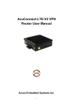
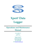
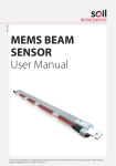
 Document Title:
CAMPBELL BASED
MULTI-CHANNEL DATA LOGGER
LITE USER MANUAL
Man158a
1(A5)
03/10/2012
Final
Ben
Scott
Stuart
Burgess
James
Kwist
Manual
No.
Revision
Date
Status
Originator
Checked
Authorised
for Issue
INDEX
1. Introduction
2. Direct Connection Setup
2.1 Hardware
2.1.1 Hardware for connecting using the RS232 Port
2.1.2 Hardware for connecting using the CS I/O Port
2.2 Loggernet setup
3. Accessing Data from a Data logger
3.1 Viewing current data
3.2 Downloading data
1.
Introduction
This guide details the operations needed to Connect and Download Data from itmsoil
Instruments Data Acquisition System (DAS). This is done by using the datalogger
support software Loggernet software (D2-1.1). Data is stored within the dataloggers
memory, when the memory limit is reached the oldest readings will start to be
overwritten. Routinely connecting and downloading readings from the datalogger to a PC
will ensure the readings are backed up.
2.
Direct Connection
2.1 Hardware
On the CR800 and CR1000 there are two 9 pin ports that can be used for connecting
into the data logger. These are the RS232 and CS I/O port (See Figure 1.)
Figure 1.CS I/O and RS-232 9 pin ports shown on a CR800
Note: Some loggers will already have other peripherals attached to these ports eg.
A Modem or AVW200. If this is true ideally it is advised not to use these ports. If no
other option but to remove one of the connections make sure they are reconnected in the same way. Removing some peripherals may mean that it is not
possible for live readings to be taken.
2.1.1 Hardware for connecting using the RS232 Port
For connection using the RS232 port a male to female 9 pin RS232 serial cable is
required (See Figure 2.).
Figure 2.RS232 Cable
Note: Most PCs and Laptops will have a 9 pin VGA output; this is not suitable for
connecting the Logger via a RS232 Serial cable to.
This then needs to be connected to a PC or Laptop. Not all modern laptops and PCs will
have the necessary serial output. To solve this a USB to RS232 cable (D1-3.11) can be
used (See Figure 3.). This will require drivers to be installed for the cable to be recognised,
a CD containing the drivers will accompany the cable.
Figure 3.USB to RS232 Cable
2.1.2 Hardware for connecting using the CS I/O Port For connecting using the CS I/O port of the data logger a special cable or adapter is
required (See Figure 4.& 5.) Figure 4.RS232 to CS I/O Cable
Figure 5.RS232 to CS I/O Adapter
2.2 Loggernet setup
Figure 6.Highlight “Main” then select “Setup”
Note: The following screen is the “EZ View” which guides through the setup. If your
view is not the same please select the icon in the top right of the screen:
Figure 7.Select “Add”
Figure 8.Select “Next”
Figure 9.Select the logger type and assign a name.
This will either be a CR800 or CR1000. If unsure please either physically inspect the data
logging system or view the wiring diagram to identify your logger type.
Figure 10.Select the connection type. Select “Next”.
Figure 11.Select the “Com Port” the logger is connected to.
Note: If the cable is correctly attached to the PC and the driver has been installed
correctly it will be listed in the drop down box. If the cable is not shown please use
“Device Manager” in windows to identify the correct Com port or diagnose any
issues. Once this has been done close and then reopen the Setup window and the
EZSetup wizard.
Figure 12.Select the applicable baud rate.
This may differ depending on the setup of the logger. Please refer to the wiring diagram as
the ports on the logger will have their baud rates labelled on them.
Figure 13.Select “Finish”
3.
Accessing Data from a Data logger
Once the above setup is completed under the main menu select “Connect” (See Figure 14.)
Figure 14.Opening the Connect Screen On the Connect Screen highlight the logger that was setup and then select “Connect”(See
Figure 15.)
Figure 15.Highlight the logger and select “Connect”
3.1 Viewing current data
Once connected it is possible to view the last readings taken and change some of the logger
parameters. This is done by accessing the “Public table” from the drop down menu on the
connect screen (see Figure 16.).
A
B
C
D
E
F
Figure 16.Once connected select the “Public” table The details within the public table will differ for every data logger. Though the features that
are consistent are:
A. RecNum
-
This will tell you how many scans have been performed since the logger
has been switched on. This will not indicate how many readings have
been taken but how many times the program has checked if the DoMeas
is true. This will usually scan every minute (see A on Figure. 16.).
B. TimeStamp
- This will display the current time set in the logger. This can be adjusted to
the time of the PC connected to the logger by using the “Set” button in the
top right corner (see B on Figure. 16.).
C. ProgVer
- The current version of the program (see C on Figure. 16.).
D. LoggerID
- The last three digits of the logger identification number
(see D on Figure. 16.).
E. MeasIntv
- The measure interval in minutes. This can be set by clicking on the
number and retyping the number of minutes you wish to set the interval
to, then pressing enter. In most cases this can be set between 1 to1440
minutes. If set out of this range it will reset to the default measure interval
(the interval asked for when the logger was purchased). When the logger
is turned off and back on this will also reset the measure interval to its
default (see E on Figure. 16.).
F. DoMeas
- When this is true the logger will take a reading on the next scan (in most
cases this will be on the next minute). This will be true when the logger is
first powered on. This can also manually be set to true by clicking on
false, typing true then pressing enter (see F on Figure. 16.).
The other values shown will mainly be the most recent readings. These can be associated
with the wiring diagram by the mux (multiplexer) number and sensor number. They will also
indicate sensor type and unit.
3.2 Downloading current data
To download data you will need to connect to the data logger as detailed above then select
the “Collect Now” button at the top of the connect screen (see Figure. 17.).
Figure 17. Collect Now
Figure 18. Collecting Data
Once the data is collected it will produce data files that are in comma separated format
These will be named in the style:
SalesOrderNumber_WhatData_LoggerID.dat
There may be several of these for different units or for different instrument types.
The ‘File Name’ column will indicate the location on the computer that the file has been
saved to (See Figure 19.).
Figure 19.DataTables Collect
The data files can easily be uploaded straight in to ARGUS (D4-2.0) which is custom
configured to deal with data from data loggers. There are also advanced options in the setup
screen which allows for this to be scheduled and run automatically.
Alternatively the data can be viewed and manipulated in Excel or a similar data processing
program. The data is comma separated.
For further advanced guides or technical support please go to www.itmsoilsupport.com to
view various knowledgebase articles or submit a support ticket.