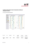
1
Man 228
MAlog User Manual
Soil Instruments Limited has an ongoing policy of design review and reserves the right to amend these specifications without notice.
Man228 MAlog – MN0814 – Rev1.0.1
1
What’s this manual about? This manual tells you about the MAlog system and how to
set up an MAlog.
Who does this apply to?
Installers and field engineers who need to install, commission
and maintain an MAlog system.
2
Welcome!
Thank you for choosing the Soil Instruments MAlog system.
This manual has been written to help you utilise all of the
functions of the MAlog. Please read this manual thoroughly
before use to help avoid any problems and keep it handy
when using the MAlog system.
MAlog
The MAlog (Milli-Amp logger) is designed as a low power,
easily installed, web-enabled data acquisition system which
can read 4-20mA sensors and pulse sensors. You can control
and configure the logger using a web portal.
3
Contents
PART I – OVERVIEW6
Introduction8
Important Information8
System Description9
System Components
9
Quick Guide to using the MAlog
10
PART II – DETAILED MALOG USER GUIDE 12
Powering the MAlog14
Enter SIM card credentials
16
Connecting Sensors to the MAlog
17
Sensor Connectors17
2 Wire 4-20mA Loop Powered Sensor
18
3 Wire 4-20mA Externally Powered Sensor
18
Mechanical Pulse Signal19
Electronic Pulse Signal19
Things to Note when Connecting Sensors
20
Interpreting the Status Lights
21
Antenna Considerations23
PART III – MALOG WEB PORTAL USER GUIDE
24
Using the MAlog Web Portal
26
Logging into the MAlog Web Portal
26
Editing an MAlog’s Details
27
Configuring the Sensor Settings for an MAlog
30
Creating Graphs37
Finding and Interpreting Data Files
40
Converting Readings to Engineering Values
41
PART IV – MAINTENANCE GUIDE 42
Maintaining the MAlog System
44
Routine Maintenance44
Battery Maintenance44
SIM Card Replacement45
4
PART V – APPENDICES46
Appendix A – Power Connection Options
48
Option 1 – Buccaneer Connector
48
Option 2 – Battery or Mains Powered
49
Appendix B – Connector and Wiring Information
50
MAlog Power Lead50
MAlog Sensor Lead50
Appendix C – Installation and User Guide for
MAlog Configuration Tool51
Installing the MAlog Configuration Tool
51
Setting the APN54
Setting the Username54
Setting the Password55
Inserting the SIM Card
56
Appendix D – MAlog Input Electrical Specifications
57
Appendix E – Sensor Connection Options
58
Option 1: The MAlog Sensor Lead with an In-line
Buccaneer Connector58
Option 2: The MAlog is Supplied Ready Installed in
an Enclosure59
Appendix F – FAQ (Frequently Asked Questions)
60
PRECISELY MEASURED
instrumentation and monitoring
5
Part I – Overview
6
contents
This section contains the following topics.
TOPIC
Introduction
Important Information
System Description
Things you need to know about the MAlog
System Components
Quick Guide to using the MAlog
SEE PAGE
8
8
9
9
9
10
7
Introduction:
Important information
The following symbols are used throughout the manual
IMPORTANT
INFORMATION
QUESTION
WARNING
! Important: Failure to adhere to the warnings in this manual
may result in network disruption and possible data loss.
Failure to observe the warning may result in injury, product
malfunction, unexpected readings or damage to the product
that may invalidate its warranty.
TIP
Tips give additional information that may be helpful when using MAlog.
PRODUCT
CHANGES
Soil Instruments has an on-going policy of design review and
reserves the right to amend the design of their product and this
instruction manual without notice.
WARRANTY
Refer to our terms and conditions of sale for warranty information.
The batteries are a consumable item and are excluded from the
warranty.
DISPOSAL
Products marked with the symbol are subject to
the following disposal rules in European countries:
• This product is designated for separate collection at an
appropriate collection point
• Do not dispose of as household waste
• For more information, contact Soil Instruments or the local
authority in charge of waste management.
WEE/DE3326WV
8
System Description
Things you need to know about MAlog
FEATURES
• Can simultaneously read up to five sensors: Connectors 1 and
2 can both read a 4-20mA analogue input and a pulse input;
Connector 3 can read a 4-20mA analogue input
• Data uploaded wirelessly and automatically to MAlog web portal
• Connects to the Internet using a SIM card with wireless data plan.
• No fixed IP address required
• Can store up to 1.5 million data-points
• Low power consumption, battery life up to six months when
using a 7aH lead acid battery
• Compatible with loop-powered or external-powered mA sensors,
and mechanical or electronic pulse sensors.
System Components
THE MALOG
The MAlog is the device that will energise and read a sensor or
sensors, digitise that reading and then send it to the web via its
inbuilt GPRS.
MALOG WEB
PORTAL
Residing on a cloud-based server, the software is used to send
commands to the MAlog to configure its settings (sensor type,
reading interval, transmit interval), and to receive the MAlog data.
Details of MAlog
Power connector (5-20VDC)
Antenna
Connector 1:
for one 4-20mA
analogue sensor
and one pulse sensor
Status
Lights
Connector 3:
for one 4-20mA
analogue sensor
Connector 2:
for one 4-20mA
analogue sensor
and one pulse sensor
9
Quick Guide to Using the MAlog
The MAlog is designed for quick and easy deployment in the field:
BEFORE YOU
GO TO SITE:
• Power on the MAlog.
• Enter the Access Point Name (APN), user name and password
into the MAlog using the Series Programming Interface (SPI).
The APN, user name and password should be provided to you
by your wireless data provider.
• Install the SIM card.
• Check the LED status lights to confirm that the MAlog is
functioning properly.
• Power down the MAlog.
WHEN YOU
ARE IN THE
FIELD:
• Wire all the sensors to the MAlog.
• Power on the MAlog.
• The status lights should become active to indicate
successful detection of the SIM card, connection to the
internet and connection to the MAlog web portal.
• The logger will now take one reading – check that the
Sensor light blinks when it is taken. It will report this
reading immediately.
• After successful connection to the web portal, all lights
will turn off to conserve the battery. The Sensor light will
also stop blinking. The lights will only operate again for
a short time when the MAlog wakes up to take a reading
or to communicate with the web portal such as to send
the data.
FROM YOUR
OFFICE:
• Log on to the MAlog web portal (MAlog.itmsoil.com)
using the details supplied when you bought the MAlog.
You can now check the MAlog is functioning as expected.
The MAlog will appear under its Logger ID on the Sites
page.
• Set up which sensor to read, reading schedule, uploading
intervals and reports in graphical and tabular formats
from the web portal.
• Start monitoring.
Please refer to Part II – Detailed MAlog User Guide and Part III –
MAlog Web Portal User Guide in this manual for more details of
each step.
10
11
Part II – Detailed
MAlog User Guide
12
contents
This section contains the following topics.
TOPIC
SEE PAGE
Powering the MAlog
14
Enter SIM Card Credentials
16
Connecting Sensors to the MAlog
17
Sensor Connectors
17
2 Wire 4-20mA Loop Powered Sensor
18
3 Wire 4-20mA Externally Powered Sensor
18
Mechanical Pulse Signal
19
Electronic Pulse Signal
19
Things to Note when Connecting Sensors
20
Interpreting the Status Lights
21
Antenna Considerations
23
13
Powering the MAlog
POWER
REQUIREMENTS
The MAlog requires a DC power source that can deliver at least
500mA peak current and is in the range of 5 to 20 volts. Typical
power sources are a 12VDC lead acid battery with or without a
charger.
While the MAlog will continue to function at a voltage down to 5
volts, an mA sensor connected to it will not necessarily work unless
the voltage requirement of the sensor is met.
TIP
POWER
CONNECTOR
The exact voltage of the power supply for the MAlog will depend
on the voltage requirement of the mA sensors.
The power connector is the located on the top left of the MAlog.
Power connector (5-20VDC)
14
CLOSE UP
OF POWER
CONNECTOR ON
TOP OF MALOG
Note the notch is at the top of
the connector
5-20VDC
Ground
The MAlog is supplied with a power cord with a 2-pin female
connector on one end and two bare wires on the other (coloured
brown and blue).
You should connect the brown wire to the 5-20 VDC terminal and
the blue wire to the ground terminal of the power source.
OTHER POWER
CONNECTION
OPTIONS
You can order other power supply accessories from Soil Instruments
to meet your needs. Depending on the MAlog package you have
bought, you have two options for connecting to a power source:
• Option 1 – Package with Buccaneer connector – This option
allows you to make an IP68 inline power connection easily
(see Appendix A).
• Option 2 – Package is Battery or Mains Powered – This option
is supplied with an enclosure (see Appendix A).
You can also make up your own sensor leads by using the
information on connectors and wiring schemes in Appendix B.
15
Enter SIM Card Credentials
The MAlog communicates with the MAlog web portal via the cellular
(GSM/GPRS) data network. To enable the link you will need a SIM card
with a wireless data plan. To uniquely identify you, your wireless data
provider will provide you with the following credentials:
• Access Point Name (APN) – for example “general.t-mobile.uk”
• Username
• Password
If you are supplying your own SIM card, you will need to enter the
above information into MAlog by following the procedures below.
You will need:
•
•
•
•
•
TIP
You do not need a fixed IP address.
STEP
1
ACTION
Install “MAlog Configuration Tool” on your PC (for details see Appendix C).
2
Remove the cover from the MAlog.
Attach a power supply to the MAlog.
Please note: there is no on/off switch on the MAlog so the unit will be on
as soon as a power supply is attached.
Connect the supplied Serial Programme Interface (SPI) to the MAlog.
3
4
5
6
7
8
9
10
11
12
16
Phillips screwdriver
Serial Programming Interface (SPI)
PC running Windows
MAlog Configuration Tool
SIM card with wireless data plan.
Connect the cable from the SPI to a spare USB port on a PC or laptop.
Open the MAlog Configuration Tool and follow the onscreen instructions
to select com port, then to set APN, user name and password for your SIM
card – see Appendix C for details.
Disconnect the power supply from the unit.
Before inserting the SIM card, ensure that you have the APN (Access Point
Name), user name and password for the SIM card. The APN, user name
and password should be provided to you by your wireless data provider.
Insert the SIM card, being careful with the alignment – see Appendix C for
detailed instructions.
Replace the cover correctly on the MAlog, so that the MAlog aerial is at
the top and the Soil Instruments logo is the correct way up.
Re-attach power to the MAlog. Check the LED status lights to confirm that
the MAlog is functioning properly.
The MAlog is now ready to use.
Connecting Sensors to the MAlog
SENSOR
CONNECTORS
The MAlog has three sensor connectors:
Sensor connector 1:
for one 4-20mA analogue
sensor and one pulse
Sensor connector 3:
for one 4-20mA analogue sensor
Sensor connector 2:
for one 4-20mA analogue
sensor and one pulse sensor
SENSOR
CONNECTORS
1 AND 2
View of sensor connector 1 (or 2) on the MAlog
+VE
Ground
-VE
Pulse Input
SENSOR
CONNECTOR 3
View of sensor connector 3 on the MAlog
+VE
Not Used
-VE
Not Used
You can find the electrical specifications for sensor inputs in Appendix D.
The MAlog is supplied with three sensor leads, each with a 4-pin male
connector on one end and four bare wires on the other (coloured
brown, white, green and yellow). Overleaf are descriptions on how to
connect the various types of sensors to MAlog.
17
2 Wire 4-20mA Loop Powered Sensor
Using the supplied pigtail sensor cable connect the yellow wire to the
-VE terminal or wire of your sensor. Connect the brown wire to the +VE
terminal or wire of your sensor (see figure below).
A stabilisation time must be set on the MAlog web portal for any
channels wired in this way. The number of seconds set corresponds
to the length of time the MAlog will switch power to the sensor before
taking a reading.
WIRING SCHEME
TO 2 WIRE
LOOP POWERED
4-20mA SENSOR
3 Wire 4-20mA Externally Powered Sensor
Using the supplied pigtail sensor cable, connect the brown wire
to the +VE terminal or wire of your sensor. If the MAlog and sensor
are being powered by different power supplies, a common ground
must be connected between them. A simple way of achieving this
is to connect the yellow wire of the MAlog cable to the -VE terminal
of your sensor. If the MAlog and sensor are being powered from the
same supply, a common ground is already present and only the VS+
to VS+ is required.
SENSOR CABLE
TO EXTERNALLY
POWERED
4-20mA SENSOR
18
Mechanical Pulse Signal
Using the supplied pigtail sensor cable, connect the green and white
wires to either side of the switch. Polarity does not matter in this case.
SENSOR
CABLE TO
MECHANICAL
PULSE OUTPUT
SENSOR
Mechanical Pulse Output Sensor
Electronic Pulse Signal
Using the supplied pigtail sensor cable, connect the green wire to the
Pulse Output terminal or wire of your sensor. Connect the white wire
to Ground.
SENSOR CABLE
TO ELECTRONIC
PULSE OUTPUT
SENSOR
Output
Ground
Electronic Pulse Output Sensor
TIP
If your sensor is not supplied by Soil Instruments, please identify your
sensor’s connections in line with Soil Instruments connections.
If you require assistance, please contact the manufacturer of the
sensor or Soil Instruments support centre.
19
Things to Note when Connecting Sensors
Remember that, if the MAlog has been used at any time prior to
sensor connection, ensure that either:
• The MAlog is set to the sensor type before the sensor is
wired to the MAlog, or
• The sensor routines are inactive.
Failure to do so may cause damage to the sensors.
WHEN
INSTALLING A
SENSOR
• Only a qualified person may install sensors
• Never wire sensors to an MAlog when it is switched on
• Check all connections before powering the MAlog.
See the calibration certificate supplied with the instrument for the
correct wiring details for the sensor you are installing.
When connecting sensors we recommend connecting at least two to
three different sensors (if being used in the field) to the MAlog in the
office. This will allow you to become familiar with the system before
doing this in the field.
TIP
When the sensor is connected, make a note of the serial number on
the MAlog, the serial number on the sensor and the type of sensor
connected to it.
By default no sensor routines are active:
• If using an MAlog previously in use on another project, please
ensure that the sensor routines are inactive when connecting a
sensor (unless that sensor is of that routine)
• See Part III – MAlog Web Portal User Guide for details of how to
configure the sensors.
OTHER
SENSOR
CONNECTION
OPTIONS
You can order other sensor connection accessories from Soil Instruments
to meet your needs. Depending on the MAlog package you have
bought, you have two options for connecting to a power source:
• Option 1 – supplied with sensor lead using an in-line Buccaneer
connector. This option allows you to make an IP68 inline sensor
connection easily (see Appendix E).
• Option 2 – supplied with connector block. This option is supplied
with an enclosure (see Appendix E).
You can also make up your own sensor leads by using the information
on connectors and wiring schemes in Appendix B.
20
Interpreting the Status Lights
The status lights on the MAlog give an indication of the current task that
the MAlog is undertaking. Please familiarise yourself with the meaning
of the status lights.
1. Ensure the sensors and power supply are already connected
to the MAlog.
2. The three signal strength indicator lights will become active
(1 = low, 3 = good signal). Position the antenna to get the
maximum signal bars possible.
Signal Strength indicator lights:
1 lit up = low signal
2 lit up = adequate signal
3 lit up = good signal
3. The SIM light should then become active to indicate that a SIM
card is detected. This should happen within approximately 10
seconds of start up, but please note that if the product has been
shipped internationally, the SIM light may take several minutes
to lock onto the local GSM provider network.
SIM light: lights up to show a
SIM card is detected
21
4. The GPRS light should then become active to indicate a
successful connection to the GPRS network.
GPRS light: lights up to show
a successful connection to the
GPRS network
5. The Web light should become active to indicate a successful
end-to-end connection with MAlog.itmsoil.com
Web light: lights up to show a
successful connection to the
MAlog web portal
6. Check that the Sensor light blinks on power up. This will happen
once and then read according to the sampling interval
Sensor light: blinks on power
up, then blinks according to
the read interval (in this figure,
Sensor 1 is connected).
22
7. The logger will take one reading when powered on and report
it straightaway. After that, it will operate a default 15-minute
read with a two hour upload or according the interval set. So,
after the first power on read, the first data will be available
to download two hours later and every two hours thereafter.
They can be verified using the web portal, SMS or WAP.
8. If you require a quicker upload, you may set this using the web
portal. The minimum upload schedule is one minute. 9. After successful connection to the internet, all lights will turn
off to conserve the battery. The Sensor light will also stop
blinking. The lights will only operate again for a short time
whenever the MAlog wakes up to take a reading.
Antenna Considerations
The MAlog is supplied with a 0dB (minimum recommended gain)
stubby antenna, which should be sufficient when in reasonable GSM
cellular coverage. The antenna is integrated in the MAlog. As a result,
when you change the position of the MAlog, the GPRS signal strength
will also change. In some cases you may need to use a high-gain
antenna with extension cable to ensure maximum signal strength.
Signal strength can be determined on site by reading the three
Received Signal Strength Indicator (RSSI) Lights as in Step 2:
No green light
1 green light
Insufficient Signal detected. Try installing a better antenna.
Sufficient Signal detected. You should change logger position, or install
vertically if possible, in order to improve the signal strength.
2-3 green lights Good Signal. No action required.
When an MAlog fails to function, the most likely reason is insufficient
signal strength, so it is important to ensure that MAlog is always
installed with at least 20% GSM signal strength (according to the signal
strength as reported on the web portal).
Always use higher-gain antennas with extension cable where signal
improvement is required, but beware of increased scope for ‘user-error’
when adding more cable, connection, etc. Never expose antenna
connectors to the weather.
You should never place an MAlog with antenna inside a
metal enclosure.
Always use an external antenna if the MAlog is housed in a
metal enclosure.
23
Part III – MAlog
Web Portal User
Guide
24
contents
This section contains the following topics.
TOPIC
Using the MAlog Web Portal
SEE PAGE
26
Logging into the MAlog Web Portal
26
Editing an MAlog’s Details
27
Configuring the Sensor Settings for an MAlog
30
Creating Graphs
37
Finding and Interpreting Data Files
40
Converting Readings to Engineering Values
41
25
Using the MAlog Web Portal
LOGGING INTO
THE MALOG
WEB PORTAL
TIP
To log into the MAlog Web Portal, navigate to http://malog.itmsoil.com/
using your preferred web browser.
There are slight differences between web browsers. The following
guide was written using Mozilla Firefox to navigate and interact with
the MAlog Web Portal.
Once the login page (pictured below) has loaded, enter your username
and password in the appropriate textboxes, and then click the button
labelled Login.
If you do not know your username and password, or were never issued
with one, please contact Soil Instruments Customer Support.
LOGIN SCREEN
26
SITES PAGE
When you have logged into your account, you will be taken to the
Sites page (pictured below). This is the home page for your account
– all available configuration and setup actions can be initialised from
this page.
The most important feature of this page is the Sites table which
displays a list of all the sites registered with your account.
TIP
The MAlog Web Portal uses the term ‘site’ to refer to an individual
MAlog unit. The Sites page displays information about every MAlog
unit that you have purchased.
SITES SCREEN
Editing an MAlog’s Details
One of the first things you need to do is to configure each MAlog’s basic
settings. To open the Logger Configuration page, click on the Site Name
in the Sites table of the logger you would like to configure.
The Logger Configuration page will then pop up in its own window.
LOGGER
CONFIGURATION
PAGE
27
At the top of this page, you will see some basic information about your
logger such as: the logger name, last and next upload times, the logger’s
local time and the logger’s activity status, as well as signal and power
status. (Note: some or all of this information may be unavailable if the
logger is not powered and not currently online.)
CLOSE UP
OF BASIC
INFORMATION
BOX (AT TOP
OF LOGGER
CONFIGURATION
PAGE)
The options on the Logger Configuration page are divided into four tabs:
• Configuration
• Location
• Photos
• Billing
These tabs are described in detail below. After you have made any
changes to any of these tab screens, be sure to click the Save Changes
button to save the new settings.
Configuration Tab
CONFIGURATION
TAB SCREEN
The Configuration tab has the following fields:
• Site Name – The logger’s name. You can set this to any
appropriate value.
• Upload Frequency – The frequency at which the logger will send
its data to the web server. You can select a new frequency from
the dropdown menu.
• Time Zone – The time zone used by the logger’s local clock. You
can select a new time zone from the dropdown menu.
• Reference – A reference note for the logger. You can set this to any
appropriate value.
28
• Realtime – The time in minutes, after physically powering the
MAlog, that the web portal will instruct the logger to speed up
the logging frequency to one minute and the upload frequency
to five minutes. After this time it will revert back to the settings
set in the Web Portal.
• Date Installed – The date that the MAlog was installed. You can set
this to any date/time value.
• Web Template – The visual template the Web Portal will use. We
recommend that you do not change this value.
• Client – The owner of the logger.
• Status – The installation status of the logger.
• APN – The current APN the logger is using.
• SIM Status – The current status of the installed SIM card.
Location Tab
LOCATION
TAB SCREEN
The Location tab allows you to set a detailed description of the
logger’s location. Use the Street, Suburb, City, State and Country
fields to enter an address.
You can enter a global position of the logger using the X and Y
Co-ordinate fields.
Photos Tab
PHOTOS
TAB SCREEN
The Photos tab allows you to upload an alternative image for the
logger. This image will only be visible on the Web Portal.
To select a new image, click the Select Image button and select an
image which must be no larger than 256KB.
29
Billing Tab
BILLING
TAB SCREEN
The Billing tab shows the activation history of the logger. No
configuration changes can be made on this tab.
Configuring the Sensor Settings for an MAlog
Before the MAlog can correctly read any of the sensors connected to it,
you need to configure the logger appropriately.
From the Sites page (see page 27 for picture of Sites screen), click on
the spanner icon
in the Sites table for the target MAlog. You will
be taken to that logger’s Sensor Configuration page:
LOGGER SENSOR
CONFIGURATION
SCREEN
The Sensor Configuration page has two main sections: the Native
Inputs panel and the Other Inputs panel.
30
Native Inputs Panel
NATIVE INPUTS
PANEL SCREEN
The Native Inputs panel has four sections:
• Sensor Connector Position 1
• Sensor Connector Position 2
• Sensor Connector Position 3
• System.
The first two sections, Sensor Connector Position 1 and Sensor
Connector Position 2, have two rows each. You can configure each
position to read one Pulse Counter sensor and/or one Analogue sensor.
The third section, Sensor Connector Position 3, has one row. You can
configure this position to read one Analogue sensor.
The fourth section, System, has two rows. System is always configured
to record the Signal Strength, and can be configured to record the
battery level.
Each of the rows has six columns: Input Type (not configurable), Input
Name, Calibration, Logging, Alarms, Data. Click on any of the column
values to open the Input Settings page for that input row.
31
Input Settings
INPUT SETTINGS
SCREEN
The Input Settings page has five tabs: Input Settings, Calibration,
Logging Frequency, Alarms, and Data. There is a tab for every
configurable column in the Native Inputs panel of the Sensor
Configuration Page.
EDITING THE
INPUT NAME
The Input Settings tab will allow you to change the Input Name
for the selected input.
To change the name, type in the desired value into the textbox
labelled Input Name.
If your MAlog is part of a SCADA system, you can also enter a
SCADA Tag ID by typing in the desired value into the textbox
labelled SCADA Tag ID.
Once you have made the desired changes click the Save button to
apply the changes.
You can click the Cancel button at any time to discard any changes.
CALIBRATION
32
The Calibration tab allows you to set up a base calibration for the
input. The Pulse Counter input and Analogue Input require different
options for their respective calibrations:
Pulse Calibration
PULSE
CALIBRATION
SCREEN
The Digital Pulse Counter calibration allows you to assign a real world
value to every pulse of the sensor. The textboxes provided have the
following layout: “1 pulse = [quantity][units of the quantity][if units of
quantity is ‘other’ – enter the custom unit here]”.
Analogue Calibration
ANALOGUE
CALIBRATION
SCREEN
The Analogue calibration will allow you to set the raw high and low
range, the calibrated high and low range, the desired unit label, and
the stabilisation time which is the time in seconds the logger will
wait after powering the sensor and before taking a reading.
Once you have made the desired changes, click the Save button to
apply them. You can click the Cancel button at any time to discard
any changes.
33
Logging Frequency
LOGGING
FREQUENCY
SCREEN
The Logging Frequency tab allows you to change the rate at which the
input is read.
To change the frequency, choose a new value from the dropdown box
labelled Data Log Frequency.
You can also select the Log if changed option, to only log new data if
the value has changed since the last logged reading.
Once you have made the desired changes click the Save button to
apply the changes.
You can click the Cancel button at any time to discard any changes.
Alarms
The Alarms tab allows you to create alarms for an input.
The alarm can send out SMS messages and/or emails to a list
of recipients.
TIP
Please ensure you have an SMS-enabled SIM card.
The alarm will also display a custom message which you can set.
Each input can have a number of different alarms.
ALARMS –
INITIAL SCREEN
34
To create an alarm, select the type of alarm you would like to create
from the dropdown box as shown below, then click the Next> button.
You will be asked to fill in some control values that will be used to
trigger the alarm.
You will also be asked for a list of recipients (SMS and/or email), and you
will need to provide an Alarm Message.
Once you have provided the necessary information, click Finish to
create the alarm.
You may cancel the creation of the alarm at any time by either closing
the page, or moving on to another tab.
35
Data
DATA TAB
SCREEN
The Data tab allows you to quickly view data from the input. You will
see both a tabular and a graphical view of the selected range of data.
You can enter the date/time range of the data you would like to
view by editing the From and To entry boxes, and then clicking the
Refresh button.
From this tab you can also Import, Export and Delete data.
The Import and Delete actions cannot be undone.
36
Creating Graphs
For every MAlog you have purchased you can create pre-defined
graphs. These graphs will be saved and continually updated as new
data comes in. This allows you to quickly view all the relevant data
collected by the MAlog.
To configure the graphs for a specific MAlog, go to the Sites page
(the home page, as described at the beginning of this part of the
manual) and click the key icon
associated with the MAlog that
you want to create graphs for. Clicking the key should open up the
Graphs and Reports page as shown below:
GRAPHS AND
REPORTS SCREEN
To add a graph, click the Add row… link in the top righthand corner.
This will open the Add Graph Row window:
Press the Add button.
No other configuration is needed on the Add Graph Row window.
37
Clicking Add will take you back to the Graphs and Reports page.
There should now be an empty graph row on this page:
To edit the new graph, click anywhere in the graph area.
This will bring up the Graph window:
The first thing you will want to do is add a data series.
Click the + sign in the Data Series header block to the right of the graph:
38
From this screen you can select any of the inputs that have been
configured on this MAlog.
Click on the dropdown box labelled Input and select the sensor
whose data you want to add to the graph.
You can then fill in the rest of the options, such as the Series Name,
the Series Type, Display Rate, and you can provide a constant
multiplier to the data if you would like. There are many other
options that can be customised, such as the Display Properties,
Statistics, Y-Axes Options, and Data Filters.
Once you are happy with your settings, click the Add button to
apply your changes. You can click the Cancel button at any time to
cancel the data series selection.
After clicking Add you will be brought back to the Graph Window.
If the data series that you have added has data, you will see a plot of
it in the graph area.
At this point you can add more data series if required so that your
screen will look similar to this one below:
Once you have finished creating your graph click the Save Graph
button (
) to save the changes to the graph. You can now close
the Graph Window.
Go back to the Graphs and Reports page. You should now see the
new graph populate on this page.
If you do not see any changes, refresh the webpage using your web
browser’s refresh function. (In most browsers, the F5 key will refresh
the current web page.)
39
Finding and Interpreting Data Files
LOCATING
DATA FILES
The data files are downloaded directly from the web portal.
The format is: date ISO in column 1 and data in column 2.
To download data, open a graph of the data, select a date range
and then select Download current data to CSV. More information
is given below:
Data Graphs
DATA GRAPH
The description of the buttons in order from left to right is as follows (to
find out the name of the button, hold the cursor over the button symbol):
Move Graph – Clicks and drags the graph to move the date range
Zoom in – Zooms in on the graph
Zoom out – Zooms out on the graph
Move backwards – Moves the date of the graph backwards
Move forwards – Moves the date of the graph forwards
Save Graph – Saves the graph
Download current data to CSV file – Downloads the data to .csv Microsoft
Excel compatible file
Toggle markers for all the data series – Adds markers to the data
Add/Remove comments to the graph – Adds and/or deletes comments
Toggle comments on the graph – Allows you to see/not see the comments
on the graph
Compare data with previous data – Splits the graph horizontally and allows
you to compare the last two date ranges
Email this graph – Allows you to directly email the graph (not the data)
Toggle horizontal grid – Adds/removes horizontal grid lines
Toggle vertical grid – Adds/removes vertical grid lines.
You can change the date range of the graph by using the two boxes,
Date From and Date To. Be aware that there is a maximum date range
of 365 days or 2,000 records.
40
Converting Readings to Engineering Values
On this screen you can also enter calibration details, but this is done
using VB.NET code.
For Advanced Users only.
Please contact Soil Instruments if you need help with
entering calibration factors using VB.NET code.
An example of calibrations written in VB.NET code is shown below:
CALIBRATION
WRITTEN IN
VB.NET CODE
Converting to Argus format
The MAlog is compatible with Argus; the data can be configured to
upload directly to Argus and be displayed close to real time. If you
would like the data converted to Argus format, please contact
Soil Instruments.
Data storage and handling
The MAlog can handle 1.5 million data sets and, when the data are
sent, the internal memory is cleared – this makes it virtually impossible
to fill the memory.
41
Part IV –
Maintenance
Guide
42
contents
This section contains the following topics.
TOPIC
SEE PAGE
Maintaining the MAlog System
44
Routine Maintenance
44
Battery Maintenance
44
SIM Card Replacement
45
43
Maintaining the MAlog System
ROUTINE
MAINTENANCE
The MAlog is manufactured with multilayer circuit boards containing
surface mounted components. For this reason there are no parts which
require routine maintenance other than the replacement of the external
battery, the recalibration of the MAlog and insertion of a SIM card.
BATTERY
MAINTENANCE
The MAlog is typically powered by a 12V lead acid battery. Although the
MAlog itself will operate down to 5V, sensors connected to the MAlog will
not as they may operate at a higher voltage – please refer to the manuals
for your sensors for their battery voltage information.
The MAlog battery status can be logged at regular intervals to enable the
battery to be monitored and so avoid power loss and therefore loss of data
by your being able to replace the batteries in a timely manner.
When replacing the batteries, make sure to run all the start up tests
outlined in Parts II and III of this manual – this will ensure the MAlog is
working with the new battery.
The minimum voltage of the MAlog is 5V, but please be aware
that this is for the MAlog and not for any sensors attached to it.
Please refer to the manual for your sensor for further information.
Battery life is dependent on the following factors:
•
•
•
•
•
Battery type
Sensor type
Sensor reading frequency
Upload frequency
Ambient temperature
Through testing the MAlog has been shown to have a good battery
life: using a 12V 7Ah battery and two loop-powered mA sensors, the
MAlog lasted six months operating a 15-minute scan interval and a
two-hour upload.
44
SIM CARD
REPLACEMENT
A SIM card will need to be inserted each time the MAlog is installed –
no SIM card is supplied with the MAlog so you will need to supply your
own SIM card and replace it yourself if necessary.
Soil Instruments support may advise you if the SIM card is the cause of
any problems you may be experiencing with the MAlog, but it will be
your responsibility to supply a new SIM card.
For an idea of what data plan to buy, the following was found in testing:
Typical data volume of 0.67Mb per month while logging two 4-20
mA sensors and battery voltage every 15 minutes and uploading
data every 2 hours.
As a result, a data plan of 5Mb would be more than sufficient for a
standard read and upload rate. However, the exact data plan required
will depend on how many sensors you want the MAlog to read and
how often.
45
Part V –
Appendices
46
contents
This section contains the following topics.
TOPIC
SEE PAGE
Appendix A – Power Connection Options
48
Option 1 – Buccaneer Connector
48
Option 2 – Battery or Mains Powered
49
Appendix B – Connector and Wiring Information
50
MAlog Power Lead
50
MAlog Sensor Lead
50
Appendix C – Installation and User Guide for MAlog Configuration Tool
51
Installing the MAlog Configuration Tool
51
Setting the APN
54
Setting the Username
54
Setting the Password
55
Inserting the SIM Card
56
Appendix D – MAlog Input Electrical Specifications
57
Appendix E – Sensor Connection Options
58
Option 1: The MAlog sensor lead with an in-line buccaneer connector
58
Option 2: The MAlog is supplied ready installed in an enclosure
59
Appendix F – FAQ (Frequently Asked Questions)
60
47
Appendix A – Power Connection Options
Option 1 – Buccaneer connector
In this package, the MAlog is supplied with the power cable already
connected to a female buccaneer connector. A second, male, buccaneer
connector is supplied which fits together with the female buccaneer
connector.
BUCCANEER
CONNECTOR
To wire in the power see figure below:
CLOSE UP
OF POWER
CONNECTOR
5-20 VDC
Allignment notch
TIP
48
All buccaneer connectors have screw terminals - to open the
buccaneer connector, use the sealing cap to unscrew the front.
Ground
Option 2 – Battery or Mains Powered
In this package, the MAlog will be installed inside an enclosure; the
power cable will already be supplied and connected to the power
accessories.
If the MAlog is battery powered only, it will be ready to go – all you will
need to do is connect the power cable into the MAlog.
If you have ordered the mains powered MAlog package, then there will
be a din rail connection as shown below:
DIN RAIL
CONNECTION
KEY: Yellow/Green = Protective earth/Ground; Blue = Neutral; Red = Live
49
Appendix B – Connector and wiring information
MALOG POWER
LEAD
Connector: Switchcraft – EN3C2F-F
Pin definition:
Pin number
Wire colour
Terminal
1
Red
5-20VDC
2
Black
Ground
Pin 1 is defined by a small raised dot on the connector housing, next to
the pin.
MALOG SENSOR
LEAD
Connector: Switchcraft – EN3C4M-F
Pin definition:
Pin number
Wire colour
Terminal
1
Brown
+VE
2
White
Ground
3
Green
Pulse input
4
Yellow
-VE
Pin 1 is defined by a small raised dot on the connector housing, next to
the pin. Pins are numbered sequentially in a clockwise direction.
50
Appendix C – Installation and User Guide for MAlog Configuration Tool
INSTALLING
THE MALOG
CONFIGURATION
TOOL
To configure the MAlog a MAlog Programming Bundle is required,
this is purchased separately to the MAlog – please contact Soil
Instruments sales department if you require this bundle. The bundle
includes a Serial Programming Interface, MAlog Configuration Tool
software, and accessories.
The MAlog Configuration Tool does not require a formal installation –
double-click on the executable file to launch the program.
The program does however need ‘.Net Framework 3.5’ to be installed on
the target computer. If you do not already have the .Net Framework 3.5
installed on your computer, it is available as a free download from the web.
Please follow the link below. (This link was tested at the time of the writing
of this guide. If it no longer works, please contact Soil Instruments)
.Net Framework 3.5 download:
http://www.microsoft.com/download/en/details.aspx?id=21
Enabling config mode
STEP
1
2
3
4
ACTION
Make sure the MAlog is not powered.
Remove the cover from the MAlog by unscrewing the four holding
screws and lifting off the lid.
Remove the SIM card if one is installed. If a SIM card is not installed, skip
to the next step.
Connect the MAlog Serial Programming Interface (SPI) into the 8-pin
insert on the MAlog. The photos below shows the correct way to insert
the SPI:
51
STEP
5
6
52
ACTION
Connect the other end of the RS-232 cable to your computer. If
required, use a USB to RS-232 adapter. If using a USB to RS-232 adapter,
it may be necessary to install the appropriate drivers. Please consult
the documentation provided by the adapter’s manufacturer for more
details.
Start the MAlog Configuration Wizard on your computer. You will see
the following screen:
7
In the top blue section, select the com port from the dropdown box to
which the MAlog is connected, and click the Connect button.
8
Once you have been connected the button will change to read
Disconnect:
STEP
9
ACTION
Power the MAlog.
Please note: there is no on/off switch on the MAlog so the unit will
be on as soon as a power supply is attached.
Once the MAlog has power, if the connection was successful, you will
see boot up details written to the text box. After the MAlog has booted
and if the unit has successfully entered Config Mode (the screen
shown here), the yellow settings section of the configuration tool will
be enabled:
10
If the settings section does not become enabled, the program did not
detect the MAlog entering ‘Config Mode’.
In this case, please remove power from the MAlog.
Make sure that you have removed the SIM card from the logger.
Restart the configuration tool, and follow on from step 7 above.
Make sure you carry out step 7 before applying power to the MAlog as
stated in step 9.
11
Now it is in ‘Config Mode’, the MAlog can be programmed with the
required APN details.
53
Setting the APN
Ensure that you have the APN (Access Point Name), user name and
password for the SIM card. The APN, user name and password should
be provided to you by your wireless data provider.
Locate the APN dropdown box in the yellow settings section of the
configuration tool. You can choose an APN from the dropdown box.
If your APN is not listed as one of the items in the dropdown box, you
can type the APN directly into the dropdown box.
SELECTING AN
APN FROM THE
DROPDOWN
LIST
TYPING IN AN
APN
Once you have either selected or typed in an APN, click the Set APN
button, to send the APN to the MAlog.
RESPONSE
TEXT WHEN
YOU HAVE
SUCCESSFULLY
SET THE APN
Setting the Username
Type the required username into the textbox labelled Username then
click the button labelled Set to send the username to the MAlog:
RESPONSE
TEXT WHEN
YOU HAVE
SUCCESSFULLY
SET THE
USERNAME
54
You can also obtain the current username by clicking on the
Get button.
RESPONSE
TEXT WHEN
YOU HAVE
SUCCESSFULLY
READ THE
USERNAME
Setting the Password
Type the required password into the textbox labelled Password then
click the button labelled Set to send the password to the MAlog:
RESPONSE
TEXT WHEN
YOU HAVE
SUCCESSFULLY
SET THE
PASSWORD
You can also obtain the current password, by clicking on the Get button.
Exiting config mode
STEP
1
ACTION
Either click on Disconnect (see step 8 of Enabling config mode) and
then click on X in the top righthand corner of the screen, or close the
window by simply clicking the X directly.
2
Power down the MAlog.
3
Remove the SPI and replace the cover on the MAlog.
The MAlog will not begin to take readings until you follow the
above steps to exit the config mode and then reapply power.
55
Inserting the SIM Card
Insert the SIM card, being careful with the alignment.
Note that the SIM card needs to be inserted with care: slide the card
latch back, lift it, slide the card into the latch, click it back down and
slide to lock in place – see pictures below:
SIM CARD SLOT
IN CLOSED
POSITION –
SLIDE LEFT TO
OPEN
SIM CARD SLOT
SLID OPEN –
LIFT UPRIGHT
TO INSERT
CARD
SIM CARD
LATCH UP –
SLIDE SIM CARD
IN, PUSH LATCH
DOWN AND
SLIDE RIGHT TO
LOCK IN PLACE
56
Appendix D – MAlog Input Electrical Specifications
•
•
PULSE
COUNTER INPUT •
(ACTIVE LOW)
•
Switch contact – Maximum frequency 10Hz (debounced)
Transistor output – Maximum frequency 1kHz (not debounced)
Internal pull-up to 3.3V
Protected to 30VDC
•
•
ANALOGUE
INPUT (0-20mA), •
SINGLE-ENDED •
•
0.1% Accurate Uncalibrated
0.02% Accurate Calibrated
Option Switched Output (see below)
Internal 100Ω Resistor
Protected to 30VDC
57
Appendix E – Sensor Connection Options
Option 1: The MAlog sensor lead with an in-line buccaneer connector
SENSOR
INPUTS 1 & 2
SENSOR
INPUT 3
Connect your sensor to the plug connector shown below:
4
1
3
2
KEY:
Pin 1 = -VE
Pin 2 = Pulse Input
Pin 3 = Ground
Pin 4 = +VE
Connect your sensor to the plug connector shown below:
4
1
3
2
KEY:
Pin 1 = -VE
Pin 2 = Not Used
Pin 3 = Not Used
Pin 4 = +VE
Pins 2 and 3 are not connected on Sensor Input 3.
58
Option 2: The MAlog is supplied ready installed in an enclosure
+VE1
Switch Power Out
Ground
Ground
Pulse Input
Pulse Input
-VE1
Analogue Input
+VE2
Switch Power Out
Ground
Ground
Pulse Input
Pulse Input
-VE2
Analogue Input
+VE3
Switch Power Out
-VE3
Analogue Input
VS+
V+
VS-
GND
Sensor Connector 1
Sensor Connector 2
Sensor Connector 3
59
Appendix F – Frequently Asked Questions
Why does the Power light not light up when I apply power?
This may be caused by a flat battery or a bad connection to the
battery. Use a multimeter to check the battery power. If the battery
has full voltage and the light still does not light up, then the logger is
probably faulty. Contact Soil Instruments support.
Why are the Signal Strength lights not lighting up?
The Signal Strength lights will not light up if the MAlog can not
detect a GSM Signal. Refer to Interpreting Status Lights and Antenna
Considerations in Part II of this manual. Check to see if a GSM phone
has any signal bars – if not then you may not be able to use the MAlog
in this location. Contact itmsoilsupport.com for further assistance.
Why is the GPRS light not lighting up?
The GPRS light will not light up if the MAlog has trouble connecting to
the GPRS Network. This can happen occasionally if the local network
provider is having problems. The MAlog will automatically try a
different network, or continue retrying the same network if it is the
only one available. If the problem persists please contact your wireless
data plan provider for further assistance.
Do I need a static IP (internet provider) address to
operate the MAlog?
No, the MAlog connects to web-based software using a SIM card
(supplied by you). All communications with the web portal are
initialised by the MAlog: as a result no static IP is required.
What size of data plan will I need with my SIM card?
The size of data plan you need will depend on how many sensors
you are reading and how often you read them and upload the data.
However, Soil Instruments has found that a 5MB data plan is more
than sufficient for logging five sensors plus battery voltage every 15
minutes and uploading data every hour (although logging at this rate
will reduce the battery life).
Is there an easier way to connect sensors to the MAlog
other than by splicing cables?
Yes, you can use a buccaneer connector which is supplied with the
MAlog package number D7-3-EXP.
60
SUPPORT
www.itmsoilsupport.co.uk
+44 (0) 1825 765044
61
62
63
Bell Lane, Uckfield, East Sussex
TN22 1QL United Kingdom
t:
f:
+44 (0) 1825 765044
+44 (0) 1825 744398
e: [email protected]
w: www.itmsoil.com
Soil Instruments Ltd. Registered in England. Number: 07960087. Registered Office: 5th Floor, 24 Old Bond Street, London, W1S 4AW
64