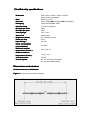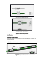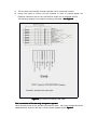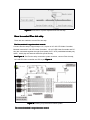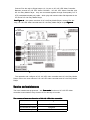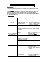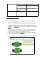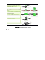
1
Flex dot Installation and Safety Manual
please read the
Welcome to use Flex Dot. In order to use Flex Dot with convenience,please
safety precautions in this section before installing, powering, operating or
servicing this product.
Features
Flex dot strip is a multi-purpose, high-intensity strip of 40 full-color LED dots generating
extraordinary effects without the constraints of fixture size or shape. Flex dot enables
patterns and video on almost any interior or exterior surface, including ceilings, floors,
three-dimensional objects, sculptures, and more. Its small node size allows installation
in tighter spaces and various shipe, which create perfect image effect.
1. Quickly deploy video over large spaces in creative ways with Flex-Dot, a flexible
LED pixel strip. It can bend, wrap, drape, and fold to conform to even most
demanding designs.
2. Create an LED screen out of uncommon surfaces and shapes, which widely apply
to stage sets, clubs, retail, even outdoor environments, enabling unique display
solutions to be realized without the long lead times or costs associated with a ‘from
scratch’ design. A cable-like construction gives flexibility for even the most arbitrary
shapes.
3. Flex-dot strips are merged into one seamless video display.
4. Individually controllable, bright, RGB pixels
5. Excellent image quality
6. IP65 for use indoors or out
Safety caution
1. While getting new purchased Flex Dot, please make sure every device is not
damaged during the transportation, if finding anything damaged, please contact
local distributor or your supplier.
2. Do not connect Flex dot strip with AC power directly, which will damage Flex dot
strip. Please check the connection drawing in the instruction for correct installation
method.
3. Please install Flex dot far away from the place where is flammable and
tend-exploding.
4. Do not install Flex Dot where the child can easily touch.
5. Once finding the scarfskin of the wire is damaged, the broken wire should be
protected or replaced;
6. If cutting Flex Dot from the middle of the strip, the terminal should be sealed, stop
it from short circuit.
7. when using at outdoor, the device of the output of signal and power should be
protected from water washing.
8. comply your local regulation of electric equipment usage.
Flex Dot strip specifications
Resolution
Pixel
Pixel size
Packaging
Whether rating
Bit depth per color
Bit depth per pixel
Viewing angle
Service life
Brightness (white)
Pixels per strip
Input voltage
Power consumption
(White)
per pixel
pixel(White)
Maximum ambient
temperature (Ta max.):
Minimum ambient
temperature (Ta min.)
Control protocol
Control system
Pitch 75mm, 100mm, 150mm, 200mm
(pitch can be customized)
RGB 3-in-1 LED
23mm (Width) x30mm(Depth) x13mm(Height)
Clear Housing/Black wires
IP 44(IP 65 optional)
16bit
48bit
120º × 120º
80000 hours
2.5 candela per pixel
40 pc
DC 12V
0.7Watts
50°C (122° F)
-20°C (-4° F)
TCP/IP
HC-105 LED Video Controller
HC-104 Easy Media Player
Dimensions and stucture
All dimensions are in millimeters
Figure 1 is Flex dot strip structure overview
Pixel size (A type, without fixing ear )
Pixel size (B type,with fixing ear )
Figure 1: Flex Dot strip overview
Installation
Installation of Flex dot strip
Unfold Flex Dot strip, fix Flex Dot strip to the track with binding tape and screw with
following methodes:
Method 1: install Flex Dot strip into special track:
I ns tal l ati on method
method( 1 )
Track
Figure 2: Fixing Flex dot strip in track
Method 2: Fix the flex dot strip on the flat object:
I nstallation
method(
2)
1:将Flex
Flex dotmethod
方法1
strip
strip安装在专用导轨中。
Self-tapping Screw(M3)
Figure 3: Fixing Flex dot strip with self-tapping screw
方法3: 将 Flex dot strip用扎带固定在支架上。
Figure 4: Fixing Flex dot strip with self-tapping screw
Fixing bracket
I nstallation method
method(
3 ) Flex dot strip with binding tape
Figure 4: Fixing
Figure 5: Fixing Flex dot strip with binding tape
The connection of Flex dot strip and HC-105 Controller
1)
2)
3)
Connect input of Flex Dot strip with output port of FLC-105 video controller ( there are
four output on the FLC-105 video controller), fasten lock nut.
Several Flex Dot strip can be connected in series, after series connection, the
maximum pixel cannot be larger than 680 pixels.
A long Flex dot strip can be retraced. See Figure 5.
Figure 5: Retrace installation drawing of Flex dot strip
4)
5)
The AC power wire between several controller can be connected in series.
Using LAN cable to connect HC-105 controller in order to transmit signal, the
maximum number of the HC-105 connected in series can not be larger than 20.
See Figure 6。
The following drawing is the mathod of making LAN cable,See
Figure 6: The mathod of making LAN cable
The connection of Flex dot strip and power repeater
When several pieces of Flex dot strip connected in serial,the power repeater should be
added between each Flex dot strip. Connect power repeater as per Figure 7:
Figure 7: Connection of power repeater and Flex dot strip
How to control Flex dot strip
There are two method to control Flex dot strip
The first method is synchronized control:
Connect Flex dot strip to Signal output 1,2,3,4 port on HC-105 LED Video Controller;
Between several HC-105 LED Video Controller,HC-105 LED Video Controller and PC,
they are connected together through Good-quality CAT 5 UTP (unshielded twisted pair)
cable,which play and transmit video file synchronously.
See Figure 8. The Flex dot strip connection system overview, connect Flex dot strip,
HC-105LED Video controller and PC as per Figure 8:
Figure 8: Drawing of synchronous control system
The second method is asynchronous control.
Connect Flex dot strip to Signal output 1,2,3,4 port on HC-105 LED Video Controller;
Between several HC-105 LED Video Controller , HC-105 LED Video Controller and
HC-104 Easy Media Player,they are connected together through Good-quality CAT 5
UTP (unshielded twisted pair) cable,which play and transmit video file deposited in the
CF card of HC-104 Easy Media Player;
See Figure 9. the system overview of HC-104 Easy Media Player, connect Flex dot
strip, HC-105 LED Video controller and HC-104 Easy Media Player as per Figure 9:
Figure 9: Drawing of asynchronous control system
The operation and configure of HC-105 LED video controller and HC-104 Easy Media
Player refer to the user manual of HC-105 LED video controller and HC-104 Easy Media
Player
Service and maintenance
The inner installed test programme,with Test mode function on HC-105 LED video
controller to test whether every function of Flex dot strip is in order.
The content of auto-test function of HC-105 LED video controller
Test mode button
Flex dot strip effect
The first time press
Full red
The second time press
Full green
The third time press
Full blue
The fourth time press
Full white
The fifth time press
Chase(white)
Operation steps:
1. Connect Flex dot strip to signal port 1,2,3,4 on HC-105 LED video controller, turn on
the power for controller.
2.
Press Test mode button. With every press, Flex dot strip will change a effect. If the
result of auto test of some LED dot strip or some dots is not consistant with effect
described above, so such Flex Dot Strip is out of order, which need to check and maintain,
sign marks on the bad Flex Dot.
Troubleshooting
Problem
Probable cause(s)
Remedy
The controller have not signal
Check controller,repair or change a
or power output
new controller
The whole Flex dot strip is
The connector between Flex
Check the connector between Flex
not working
dot strip and controller is not
Dot strip and controller, fasten the
completely contacted
connector or check the wire
connection on the connector
The color of the whole Flex
dot strip without changing
The mistake of output signal of
the controller
Check controller,repair or change a
new controller
The mistake of the configure of
Configure the controller once again
the controller
The color of One dot or
several dot in one Flex dot
The LED panel of this dot is
Check wire connection and all the
damaged
device on the damaged LED dot, or
strip is out of order, remains
replace with a new one,
are working correctly
From
some
point,
The method as per Figure 10
the
remains is not work, or do
not change color
This dot is damaged, without
Change the damaged dot LED panel
The method as per Figure 10
signal or power out
The former dot is damaged,
without signal or power output
The Flat cable and LED panel
Check this Dot, make sure all the
is not well contacted, the signal
wire is well contacted
or power cannot be transmitted
The method as per Figure 10
to the next Dot
Flex Dot strip controlled by
Controller defective
Replace with a Controller known to
be operating correctly.
One or several controller
Have faulty controller tested and
displays video incorrectly or
serviced.
does not display video at all.
The
LAN
cable
controller
is
contacted
between
not
well
Inspect connections and LAN
cables.Correct
poor
connections.
Repair or replace damaged cables
Wrong configuration
Correct the confuguration as per
software user manual
Controller defective.
Have faulty controller serviced
Fuse blown (located next to
Disconnect power cable. Check fuse
power input connector)
and replace.
The AC cable connector is not
well
contacted
Fasten the AC power connector
between
controllers
All flex dot strip display video
incorrectly
or
do
display video at all.
not
Unusable
video
signal
or
Check video source.
defective video source.
The bad conection between
Repair or replace damaged cables
PC and controller
How to maintain Flex dot strip.
1. Disconnect the power, take out the bad LED panel, take out the LED panel by
screwdriver from the plastic housing, take off the wire with electric soldering iron,
replace the bad LED panel, finally solder the flat cable on the LED panel.
2. Test with power on, if the Flex dot strip work again, turn off the power for controller.
3. Coat silicone on the front and back side of LED panel and at the end of flat wire,
cover all the device except LED. After solidification, install the plastic shell with screw.
The method as per Figure 10
Caution:
1) When changing LED panel, takec care of the direction of arrowhead of the LED
panel, the direction of the arrowhead should be the same with signal transmitting
direction, from Data/power input point to Data/power output.
2) The sequence of four wire of Flat cable must be corresponded with serial position on
LED panel. The sequence is as per Figure 10
3) When coating silicone on LED panel, all the devide and solder joint should be cover
completely, in case the circuit is short caused by water.
Figure 10
10:: Maintenance schematic diagram
End