1
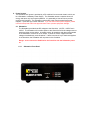
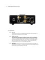
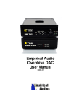
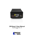
Empirical Audio
Overdrive DAC
User Manual
© 2009-2010
Overdrive® DAC User Manual
Empirical Audio Rev. 1.3
Critical – read all red warnings first to prevent equipment damage
1. Technology/Design
The Overdrive DAC incorporates our excellent low-jitter USB interface technology and
breaks new ground for D/A converter technology. The Overdrive design philosophy is
“less is more”, with one of the simplest analog paths ever devised. The Overdrive
provides solutions for the three most important issues with digital sources:
•
•
•
Jitter
D/A noise/distortion
Volume control noise/distortion
This high-performance triple solution is unprecedented and delivers a totally new sound
quality level. The Overdrive is a non-upsampling DAC (no ASRC) that has an ultrasimple analog signal path, reducing background noise and harmonic distortion to
unprecedented levels. It incorporates a preamp function that has never been tried in
ANY audio product before. This preamp function adds no devices whatsoever to the
signal path, leaving it simple and ultra-low noise. It has selectable digital filters that allow
one to tailor the sound to your personal taste. You can effectively eliminate them if you
want.
The sound of the Overdrive is simply indescribable and utterly magical. The clarity is
unlike anything you have heard before, particularly driving amps directly. Other DACs
sound muddy in comparison. The bass is tight and the detail and imaging is more than
first-rate, it’s breathtaking. Drums are rendered with more realism than any other DAC is
capable of. The leading and trailing edges and harmonics of percussion, strings and
woodwinds are delivered with true realism. Even with this level of detail and dynamics, it
still gets vocals right. The Overdrive USB DAC resets the bar for the term “accuracy” in
digital to analog conversion.
1.1. Performance
The performance of the Overdrive DAC is a result of several innovative design
breakthroughs:
1.
2.
3.
4.
5.
Low jitter USB interface module
Ultra-Simple pure Class-A analog Path
D/A Volume Control
Ultra-Linear Output Stage
Fully Balanced Analog Path
1.1.1.
Low jitter USB interface module:
This USB module is the same device that we use in our popular Off-Ramp 3 USB
rd
converter. This is a 3 generation USB converter and rates #1 against all other
converters on the market. Very low jitter, no drivers or ASIO to load, and it
converts 16/44.1 to 24/44.1 automatically. This enables bit-perfect playback from
XP or Vista PC’s and allows for 8-bits of digital volume control without any loss in
resolution. USB also handles up to 24/96.
1.1.2.
Ultra-Simple Analog Path:
The analog path consists of an I/V stage (op-amp) driving a single output
transistor through a coupling cap. All stages are run Class-A, so it gets a bit
warm. There are no resistors at all in the analog signal paths, except for very
small damping resistors on the output. Resistors add noise, so they are best
avoided.
1.1.3.
D/A Volume Control:
The revolutionary volume control is accomplished without any added parts to
the line-output signal path. It is not an entirely digital or entirely analog volume
control. It is a little of each actually. The volume is adjusted by changing the
behavior of the D/A conversion. It does NOT adjust attenuation of a resistor
divider, change the gain of an amplifier stage or truncate bits in the digital data.
All of these would add noise and/or distortion to the signal.
1.1.4.
Ultra-Linear Output Stage:
The output stage is a single transistor in Class-A mode. It is well known that this
simple configuration results in some compression distortion, but also sounds
most natural. In order to effectively eliminate this compression distortion, we
incorporated a compensation circuit in the Overdrive. The output stage
impedance is low enough and the power output high enough to drive most highimpedance headphones easily, so we provide an adapter. It can drive either
normal or balanced headphones such as Sennheiser.
1.1.5.
Fully Balanced Analog Path:
There are 4 analog paths, all identical. They connect from the D/A converter chip
to the outputs. All 4 are used for the balanced outputs, 2 of the 4 are used for
the Single-Ended outputs. Resistors provide some isolation, so all outputs may
be used. We recommend low-capacitance interconnects if all 4 outputs are used,
and shorter is better. The output drive is sufficient for all preamps and amps, and
even high-impedance headphones like Sennheiser.
1.2. Design Choices:
A number of design decisions were made in order to optimize performance and sound
quality over all other criteria:
1.2.1.
1.2.2.
1.2.3.
1.2.4.
Small Chassis size
This was critical to reducing both digital and analog signal path lengths. Long
signal paths add distortion due to circuit-board dielectrics and also introduce
more noise due to ground-plane coupling and crosstalk.
Op-Amp I/V conversion
This was necessary in order to optimize the loading of the D/A converter. Some
D/A chips require certain loading and voltage on their outputs in order to
guarantee best linearity and low-distortion.
AC-coupled output
This was chosen because the alternative of DC-coupling would not allow a pure
Class-A operation throughout, which delivers lower distortion. The coupling
capacitors available now are very close to a copper wire in performance.
AC power cords eliminated
Wall-type power supplies were chosen for best sound quality. They eliminate the
need to purchase a $1200-2K power cord, and locate the magnetic and electric
fields well away from the DAC chassis.
2. Break-in
All electronics needs a period of break-in. New capacitors and dielectric insulators must
stabilize with voltage and current applied. The Overdrive is broken-in by Empirical Audio for
approximately 5 days before shipping. An additional 25 days of 24/7 break-in is required for
full break-in, with all inputs driven. Each input breaks-in independently, so all should be
driven with a signal. Outputs do not have to be connected in order to break-in.
3. Volume settings
3.1. Volume Control
The volume control can be selected by using the recessed toggle switch on the front
panel. The switch activates the volume or line-out on power-up only, not on-the-fly. To
make a change, you must power off the Substation and back on using the front-panel
power switch. As with all systems, at initial power-on, the volume should be rotated to
its lowest setting before playing music.
3.2. Optimum Manual Control
Manual control can be optimized for performance if the volume knob is near maximum.
The gain should be selected so that the volume knob is near maximum at normal
listening levels.
3.3. Optimum Remote Control
Remote volume control capability can be achieved quite easily by using a combination of
the manual volume control, a digital volume control (such as iTunes volume) and the
USB interface. Because all 16-bit 44.1kHz sampled files (native CD sample-rate) that
are streamed using the USB interface are converted to 24-bit 44.1kHz sample-rate (bitperfect data), this provides 8 bits or 30% digital volume control before the data bits are
affected. If one adjusts the volume to a comfortable listening level with the manual
control, then only small reductions of the digital control from maximum are necessary to
adjust the track-to-track amplitude variation. This is even better than having yet another
remote control. Most of us already have too many of those. It allows you to use the
player software for everything: song selection, muting and volume control, without any
loss of resolution. This is the best possible scenario.
3.4. Gain Switch
A two-position gain switch is recessed into the front-panel. It is marked “H” and “L”.
This can be switched at any time, but will only take effect after powering down the
Substation and back up again using the front-panel power switch. For driving most
amplifiers directly with 1V sensitivity for full power, the switch should be in the “L”
position.
3.5. Range Jumpers
Two jumpers are provided to set the volume range. Three volume ranges are possible.
The range setting provides a lower volume extreme. It does not affect the maximum
volume, only the minimum volume. If the range jumpers are set for “Min”, the volume
will have the least range, so the lowest volume will still be loud. If the range jumpers are
set for “Max”, the volume control when at the minimum will be very quiet. This allows
the volume to be tailored so that a fairly wide arc can be used in adjustment for track-totrack amplitude variation.
The range jumpers are located just inside the front panel to the right of the volume
control as you look at the front panel. The settings are illustrated on the circuit board.
The default factory setting is “Max”, for widest adjustment arc. Make sure the Overdrive
is powered-off for this adjustment. The front panel must be removed to access these.
4. Power System
The Overdrive DAC power is provided by a DC umbilical from a second chassis, which can
be a Substation or a Battery Power Supply. The Substation stores a massive amount of
energy and has a very low output impedance. It is essentially a Hoover Dam to provide
power to the Overdrive. The Substation receives DC power from three wall-type power
supplies. These are high-current switchers. If you use after-market power supplies, please
insure that Empirical Audio has approved them first to prevent equipment damage.
4.1. Substation
The Substation provides three DC voltages to the Overdrive, +12VDC, +18VDC and –
18VDC. The Substation will not allow power to the Overdrive if all three voltages are not
present and the correct values. In standby mode, all capacitors and relays are powered
in the Substation, but there is no DC output. It power-on mode, it applies all three
voltages simultaneously to the Overdrive. If there is a short in any of the three supplies
in the Overdrive, the Substation will not power on the Overdrive.
Danger: never connect the Umbilical to the Overdrive with the Substation power
on.
4.1.1.
Substation Front Panel
4.1.2.
Substation Back Panel
4.2. Wall Power Supplies
Three Wall-type power supplies are required for the Substation, +12VDC, +18VDC and
–18VDC. For the –18VDC supply, the current requirement is lower. These supplies are
compatible with all international voltages. Optimum performance of the Overdrive will be
achieved with all three power supplies plugged directly into the AC mains outlets of a
single AC circuit. If your location does not have sufficient outlets for this, the next best
thing is to plug the +18VDC supply into a wall outlet and the –18VDC and –12VDC
supplies into an outlet strip or power conditioner. Plug the ground-wire from the DC
umbilical cable into the earth ground of the AC circuit.
Make sure that you use the same circuit from the AC panel for all three wallsupplies and that you power all of the Wall-Supplies first and then connect the DC
cables second. Power the Substation AFTER you connect the umbilical. Different
circuits will potentially originate from different phases and may cause ground reference
voltage differences with resulting high-currents in the ground. This can potentially
damage other components in your system. Use the same phase, and the same
circuit if possible for the entire system, including the computer.
Power conditioners can have high-impedance in the ground connection to the AC
service, so if you use a conditioner, it is best to plug all three wall-supplies into this
conditioner. Conditioners with filters generally limit the transient current-flow, so we
advise against using them in general. A low-impedance power strip, such as the PS
Audio JuiceBar II works well in this application, however a good power cord is required
to feed it from the AC wall outlet. The ground wire should be plugged into the outlet bank
where the 12VDC supply is plugged, or use the alligator clip.
5. Overdrive Back Panel Connectors
5.1. Digital Inputs
5.1.1.
I2S input
The Overdrive I2S input is compatible with the Empirical Audio I2S standard. It
can be driven with a Pace-Car or an Off-Ramp.
5.1.2.
S/PDIF coax input
The S/PDIF coax digital input can be driven from any audio device with digital
output conforming to the S/PDIF standard IEC-60958. The input impedance is
75 ohms. It is recommended that stock transports and devices other than that
manufactured by Empirical Audio use a 1.5m minimum 75 ohm digital cable in
order to minimize the jitter caused by reflections. Devices manufactured by
Empirical Audio can use a 1m 75 ohm digital cable length.
5.1.3.
USB input
The USB input can be driven with a 5m (16-foot) USB cable from any USB1.1 or
USB2.0 port on a computer. The USB port supports up to 24/96 sample-rate and
uses the native drivers in Windows or Mac OS.
5.2. Analog Outputs
5.3. RCA – Single-ended outputs
The RCA outputs are designed to drive a preamp, amplifier or high-impedance
headphones. These are AC-coupled, so there is a delay in the power output from them
on power-on in order that the DC voltage settle-out. The line output level from these is
2.3VRMS in high-gain mode and 1.0VRMS in low-gain mode. The volume control
reduces this. On power-down, the outputs disconnect from the output drivers and short
to ground. When there is no valid signal, the outputs are disconnected from the output
drivers and shorted to ground. When active, the outputs can withstand short to ground
without damage to the Overdrive.
5.3.1.
Headphone adapter
A headphone adapter is provided. The red plug on the adapter goes into the left
channel RCA output. Never use standard Headphones and the balanced
outputs to speaker system at the same time - this may cause system or
speaker damage. Also avoid high static charge on the headphone cable
when plugging it in. Ground yourself and the cable contacts first.
5.4. XLR – Balanced outputs
The balanced outputs are designed to drive a preamp, amplifier or high-impedance
balanced headphones. These are AC-coupled, so there is a delay in the power output
from them on power-on in order that the DC voltage settle-out. The line output level
from these is 4.6VRMS in high-gain mode and 2.0VRMS in low-gain mode. The volume
control reduces this. On power-down, the outputs disconnect from the output drivers and
short to ground. When there is no valid signal, the outputs are disconnected from the
output drivers and shorted to ground. When active, the outputs can withstand short to
ground without damage to the Overdrive.
5.5. Using both RCA and XLR outputs simultaneously
For best performance, this is best avoided, however this is sometimes necessary in
order to drive a subwoofer or other ancillary electronics. Each of the 4 output drivers is
shared between the balanced XLR and single-ended RCA outputs. However, there is
some isolation with small resistance between the XLR and RCA outputs. If one uses all
outputs simultaneously to a system, it is recommended that either the XLR cables or the
RCA cables be short and low-capacitance and drive a high impedance buffer or preamp.
5.6. DC Power Connector
The DC power connector is a professional 5-pin high-current locking connector. The power
inputs are:
• +12VDC Digital Power
• Digital Ground/Return
• -18VDC Analog Power
• Analog Ground/Return
• +18VDC Analog Power
6. Cooling Fan
A cooling fan is mounted inside and in the center of the top of the chassis. The fan runs
whenever the Overdrive is powered-on. A slow very quiet fan was chosen with a filter, but
some may still find it audible from the listening position. Here is one recommendation to
reduce the fan noise:
• Place the Substation on top of the Overdrive and put a U-shaped piece of foam from the
packing between them with the cut-out slot facing to the rear
• Remove the front panel and use a thin plastic screwdriver to adjust the fan down using
the blue pot that is visible just behind the volume range jumpers.
7. Overdrive Front Panel Switches and Indicators
7.1. Input select toggle switch
Selects between USB, I2S and S/PDIF coax digital inputs.
7.2. Digital Filter Select toggle switch
Selects between Low, Medium and High frequency roll-offs. High setting is the high
frequency roll-off. It is recommended to use High setting always.
7.3. De-emphasis Enable toggle switch
When enabled, it applies an equalization at the high-frequencies that eliminates
harshness due to high-frequency pre-emphasis in some recordings. “Normal” position is
recommended. The function does not take effect until a new track is started.
7.4. High/Low Gain switch – recessed
This selects between high and low gain. Only changes on power-up.
7.5. Volume/Line-Out toggle switch - recessed
This selects between volume control and line-out. Only changes on power-up.
7.6. USB Fault Indicator
USB fault is illuminated when the USB cable is unplugged at either end.
7.7. Data Error Indicator
Illuminated indicates that there is no valid data coming in on the selected digital input.
7.8. DC Power Indicator
Indicates that DC power is applied to the DC input connector.
8. USB installation and use
8.1. PC installation for 24-bit/96kHz:
1. Power-on the Overdrive DAC first and then connect the USB cable to the computer
2. Next, install DirectSound2 by copying the file “foo_out_dsound_ex.dll” from the CD-R
provided to the file folder: “C:\Program Files\foobar2000\components”
3. Next, Install the SRC resampler by copying the file “foo_dsp_src.dll” from the CD-R
provided to the file folder: “C:\Program Files\foobar2000\components”
4. Next Install Foobar2000 version 0.8.3 by copying “Foobar2000.exe” from the provided
disk to any folder on your hard disk. Execute the file by double-clicking on it after you
copy it.
5. After Foobar2000 version 0.8.3 is installed, open it by double-clicking on the Foobar Icon
on your desktop.
6. Configure Foobar2000 by clicking on Foobar2000, Preferences and make the following
selections:
a. On the left side select “Core” and on the right move the slider for “Process priority
class” to the far right, to “realtime”.
b. On the left side select “Playback” and on the right set “Output data format” to
“24bit fixed-point”.
c. On the left side select “Output” and on the right set “Output method” to
DirectSound2”.
d. On the left side select “DirectSound2” and on the right set “Device” to “Empirical
Overdrive”
e. On the left side select “DSP Manager” and on the right click on “Volume Control”
in the left field to highlight it and move this to the right field by using the =>
button. Then click on “Resampler (SRC)” in the right field to highlight it and move
it to the left field by using the <= button. Only “Resampler (SRC) should be in the
left field.
f. On the left side select “Resampler (SRC)” and on the right set “Target sample
rate” to “96000” and on the right set “Quality” to “Sinc Best”.
7. Click on “Save all” and “Close” in the Foobar Preferences window.
8. To make your first playlist, click on “Playlist”, then “Create new playlist” on the top Foobar
toolbar.
9. To name the playlist, double-click on the tab labeled “New playlist” and rename it to Jazz
or Classical etc…
10. To add tracks to Foobar2000, click on “Playlist” then “Add files…”. It will open a window
where you can select (highlight) the files in a particular folder and then click on “open”
and the files will be added to the playlist that is currently active.
11. Create a “dummy” playlist by creating a playlist and naming it “Default”.
12. Open Foobar, Preferences, Core and select the checkbox “Always send to playlist:
Default. This prevents accidental erasure of playlists.
13. Close Foobar by selecting “Foobar2000” and then “Close”.
14. If you are using Vista, you must go to “sounds and audio” in Control Panel and select
“Empirical Overdrive” for your output device.
15. If you are using Vista, highlight Empirical Overdrive from (14) above and right click and
go to “properties” and then select “advanced”. Then set the sample rate to 24/96 (or
24/44.1 if you don’t want to upsample).
16. Open Foobar2000 again by double-clicking on the Icon (this sets the thread priority).
17. To play a music file, simply double-click on the filename in the playlist and it should play.
18. There are many “skins” and different “UI’s” or User Interfaces for Foobar. These can be
found at the hydrogenaudio forums, or contact us by email.
Pitfalls to avoid:
• Don’t use iTunes on a PC, Mac only
• Don’t use the other USB ports on the computer – only one for audio
• Don’t use Dell Laptops for audio – the USB ports have a history of problems
Pops and ticks
If you experience pops and ticks because you have an older PC or have a lot of applications
running, close all extraneous applications, including:
• Screen saver
• Virus scanner
• Anything on the lower right toolbar that is not critical – many of these can be eliminated
by removing the links from “C:\Documents and Settings\All Users\Start
Menu\Programs\Startup”
• Disconnect from the internet, set priority of your player to “real-time” or at least “highest”
• If your Primary IDE Channel (C: drive) is set for PIO mode and not DMA mode, this can
cause pops. This is found in the Advanced Properties of your Primary IDE Channel under
Device Manager. PIO mode is not desirable. DMA is what you want. Windows can
change from DMA to PIO on it’s own. Go to Device Manager, uninstall Primary IDE
Channel and reboot.
If experiencing ticks on Vista, do the following:
• Set buffer length to 300msec rather than 500msec
• Run Foobar as admin
USB disconnection or Overdrive power-down
If you plan to disconnect the USB cable or Overdrive power during music playback, you must hit
the “stop” button on the Foobar2000 player first. If you pull the USB cable or Overdrive power
while Foobar is playing, you will need to close Foobar and re-open it.
To change to 24-bit/44.1kHz:
Configure Foobar2000 by clicking on Foobar2000, Preferences and make the following
selections:
a. On the left side select “DSP Manager” and on the right click on “Resampler
(SRC)” in the left field to highlight it and move it to the right field by using the =>
button. Nothing should be in the left field.
b. Always select 24-bit fixed-point in Foobar preferences, even for 44.1
You must bypass Kmixer if you are using XP. This can be achieved by Unmapping the
device, ASIO4ALL or Kernel Streaming:
To unmap the device (this is what we do):
Go to Control Panel - System Hardware - Device Manager - Sound Video and Game Controllers – Empirical
Overdrive - Right-Click and select Properties - Audio Devices – Empirical Overdrive - Properties - Set "Do
not use audio features" and set "Do not map through this Device"
You will need to reboot and then if you change it back to mapped, then you must re-boot.
8.2. Mac installation instructions:
Off-Ramp and Freeway work with Mac OSX operating systems and iTunes.
The only settings are:
•
Device select - System Preferences - Audio and Sound and select the
Empirical 1.1 as output device
•
•
Sample Rate - Utilities/MIDI options – select either 24/44.1 or 24/96
Make certain that you change the sample-rate in the MIDI settings when iTunes
is closed and then re-open iTunes every time you change the sample-rate.
9. Specifications:
Inputs:
1. USB 1.1 or USB 2.0, Mac or PC, up to 5 meter USB cable – up to 24/96 supported
2. S/PDIF coax – RCA, Canare BNC or WBT NextGen *** - up to 24/192 supported
3. I2S (Empirical standard RJ-45) – up to 24/192 supported
4. DC power (+12VDC, -18VDC, +18VDC) from included Substation
Outputs:
1. RCA left and right channels
2. XLR left and right channels
Controls:
1. Input Select
2. De-emphasis Select
3. Digital Filter Select – High, Medium, Low
4. Line/Volume Select
5. Volume knob
6. Internal jumpers for 3 volume ranges and two gain settings
Electrical:
1. RCA output Level – 1VRMS or 2.3VRMS, XLR output level – 2VRMS or 4.6VRMS
2. Frequency response – 20-20kHz +/-0.5dB
3. Output impedance – each channel 40 ohms
Included:
1. Overdrive DAC
2. Substation DC power supply – over 60,000uFd of energy storage
3. DC power supply umbilical cable
4. 5 meter USB cable
5. AC power supplies
6. CDROM with PC installation software including SRC upsamplers**
7. RCA to Phone-jack Headphone adapter – only high-impedance headphones supported
Specifications are subject to change without notice.
© 2009 Empirical Audio all rights reserved.