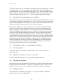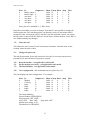
1
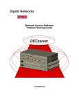
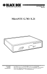
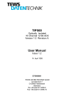
,VVXH%
Operators Manual.
Multilog with Piper.
Contents
x
x
Introduction
x
Buffer memory size
x
Front panel leds
x
Rear panel connectors - RS232 pin outs
x
Battery disconnect button
x
x
Opening a unit
x
Configuration through the front panel
x
x
The Barriers – BS6301 compliance
Principal features and specification
Configuration through the Piper port
x Battery disconnection warning
Setting associated Piper
Mutek Transcom Ltd.
Farleigh House, Frome Road, Bradford on Avon, Wiltshire. BA15 1LE
Tel (44) 0 1225 866501. Fax (44) 0 1225 865083
Email – [email protected]. Web – www.mutek.co.uk
,VVXH%
:DUQLQJ ±
0XOWLORJKDVWKHLQWHUQDOEDWWHU\SHUPDQHQWO\
FRQQHFWHG,IPDLQVSRZHULVUHPRYHGWKHXQLWZLOO
FRQWLQXHWRUXQRQEDWWHU\SRZHU
7RSRZHUGRZQWKHXQLWIRUVWRUDJHRUWUDQVSRUW
SUHVVWKHEDWWHU\GLVFRQQHFWEXWWRQRQWKHEDFN
SDQHO
)DLOXUHWRGRWKLVZLOOUHVXOWLQWKHXQLWUHPDLQLQJ
SRZHUHGXQWLOWKHORZEDWWHU\WULSFLUFXLWDXWRPDWLFDOO\
WXUQVWKHXQLWRIIWRDYRLGGDPDJHWRWKHEDWWHU\
,IWKLVKDSSHQVWKHXQLWPD\QHHGDIHZPLQXWHV
FRQQHFWHGWRPDLQVSRZHUEHIRUHLWEHJLQVWR
RSHUDWHFRUUHFWO\
,VVXH%
Introduction.
The Multilog intelligent call logging buffer is designed to provide a secure and
complete PABX call record buffer, incorporating a V24 barrier meeting the
requirements of BS6301, a call record buffer and ‘Piper’ - a V24 to ethernet converter
to deliver call records across an ethernet network. The buffer unit is provided with a
no break power supply to allow the unit to continue to collect call records without data
loss in the event of mains failure, for up to 4 hours. It also provides remote
management features to avoid the need for a site visits.
Block diagram.
3$%;
9
%6
9
%DUULHU
9
%XIIHU
5HDU3DQHOFRQQHFWLRQV
9
5LEERQ
FDEOH
3LSHU
(WKHUQHW
,VVXH%
RS232 port pin outs.
PABX port.
This port is the input to the buffer. It is set as a DTE by the internal links JP4 being set
‘side to side’ Note that +12V is presented on pin 25.
:LULQJRIWKHFRQQHFWRUWKDWFRQQHFWVWRWKHEXIIHULQSXWSRUW
3LQ 6LJQDO
'LUHFWLRQ
6DIHW\JURXQG
5[GDWD
2XWRIXQLW
7[GDWD
,QWRXQLW
&76
2XWRIXQLW
576
,QWRXQLW
6LJQDOJURXQG
9
2XWRIXQLW
Note- Auxiliary input ports if present are also linked as DTE. There are no DTE/DCE
configuration links for these ports.
Buffer output Port and buffer set up.
This port is normally linked to the Piper input by a ribbon cable (wired straight
through) on the back panel. It is set as a DTE by the internal links JP7 being set ‘side
to side’.
:LULQJRIWKHFRQQHFWRUWKDWFRQQHFWVWRWKHEXIIHURXWSXWSRUW
3LQ 6LJQDO
'LUHFWLRQ
6DIHW\JURXQG
7[GDWD
2XWRIXQLW
5[ GDWD
,QWRXQLW
576
2XWRIXQLW
&76
,QWRXQLW
6LJQDOJURXQG
'&'
,QWRXQLW
'75
2XWRIXQLW
9
2XWRIXQLW
The buffer can be configured through this port using ‘star’ commands described later.
To configure the buffer –
x
x
Unplug the link cable on the back of the unit and plug a terminal set for 9600
baud, 8, N, 1 into the buffer output port (lower) connector.
Type *H to see the command summary and enter *W to see the current settings.
Piper input port and set up.
Piper, the V24 to ethernet converter, can be configured by connecting to the upper of
the two connectors normally linked by ribbon cable. This port is wired as DCE. For
full instructions on Piper see the ‘Piper User Guide’ at
KWWSZZZPXWHNFRXNGRZQORDGVKWP
,VVXH%
:LULQJRIWKHFRQQHFWRUWKDWFRQQHFWVWRWKH3LSHULQSXWSRUW
3LQ 6LJQDO
'LUHFWLRQ
6DIHW\JURXQG
7[GDWD
,QWRXQLW
5[GDWD
2XWRIXQLW
576
,QWRXQLW
&76
2XWRIXQLW
6LJQDOJURXQG
'&'
2XWRIXQLW
The important set up information for Piper used in a Combo Multilog is briefly
described here –
x
x
x
x
x
x
Unplug the link cable on the back of the unit and plug a terminal set for 9600
baud, 8, N, 1 into the Piper input port (upper) connector.
Type ++++ to enter Piper command mode.
Main menu item 2 allows a unit to be set up. Enter the factory default name Piper,
or the unit’s IP number if known. Enter the password ‘pass’.
Configure unit sub-menu item 7 allows IP numbers to be entered. Enter three IP
numbers – the IP number of the unit itself, the IP number of the default gateway
and the sub-net mask.
Configure unit sub-menu item 2 allows serial port 2 settings to be entered. Set the
baud rates to match the buffer output (default is 9600 baud); set the number of
data bits, stop bits and parity to match the buffer output (default 8,N,1); set the
handshake to Hardware. Hardware handshake allows Piper to stop and start the
buffer output with its CTS signal.
Piper serial port 2 is normally connected to the buffer output by a ribbon cable on
the back panel. Reconnect this link cable after setting up the unit.
Buffer memory size.
Buffer sizes of 256k to 32Mb are available. At power on time a memory test checks
the fitted memory. Note - the 16mb and 32mb units cannot be fitted with auxiliary
input ports.
Battery disconnect / Reset button.
This button has two functions – when mains power is present it acts as a reset button.
When mains power is lost and the unit is running from the battery, it disconnects the
battery and the unit powers down. Note - to prevent damage to the battery, a low
battery voltage detector automatically disconnects the battery and powers down the
unit if the unit runs without AC mains power for an extended period of time.
Front panel LEDs.
There are six LEDs showing through the window on the lower RHS of the membrane
switch. They are assigned as shown –
,VVXH%
0DLQV
6WDWXVOHG
9SUHVHQW
'&'&767;'5;'
When AC mains power is present the +5V and mains present LEDs are on. If the AC
mains fails, only the +5V led will be lit.
The status led operation follows the time honoured arrangement: – off = no data;
flashing = data present; on = data arriving and/or data being transmitted.
The modem LEDs are not applicable to a unit fitted with Piper.
Opening a unit.
Unplug the mains and all D connectors. Press the battery disconnect button to power
down the unit.
Underneath the unit - loosen the four M4 screws holding the rear plastic corners and
remove them. Remove the four M4 screws holding the front plastic corners. Remove
the two M4 screws in the middle of each long edge. On the two sides of the unit –
remove the six M3 screws, one at the front and two at the back on each side. Turn the
unit on its side and slide the top cover away from the bottom plate / PCB assembly.
The rear panel remains connected to the PCB by the internal mains wiring.
,VVXH%
7KH%DUULHUV
7KHUHDUHGLVWLQFWEDUULHUVLQWKH5HY0XOWL/RJXQLW
x
x
x
7KHFRQQHFWLRQWRDWHOHSKRQHOLQHKDVDEDUULHUEHWZHHQWKHOLQHDQG
WKHORZYROWDJHDUHD7KLVEDUULHUFRQVLVWVRIDOLQHWUDQVIRUPHUDQG
RSWRFRXSOHUV
7KH3LSHUSRZHUVXSSO\KDVDEDUULHUEHWZHHQWKHPDLQVDQGWKHORZ
YROWDJHDUHD7KLVLVWKHWUDQVIRUPHULQWKHSOXJWRSVW\OH368
7KH0XOWL/RJERDUGFRQWDLQVDEDUULHUEHWZHHQWKHPDLQVDQGWKHORZ
YROWDJHDUHD 7KLVFRQVLVWVRIWKHPDLQVWUDQVIRUPHUDQGWKH3&%XSRQ
ZKLFKLWLVPRXQWHG7KLVEDUULHUDOVRLQFOXGHVWKHLQVXODWLRQFUHHSDJH
DQGFOHDUDQFHUHTXLUHPHQWVWKDWDSSO\WRWKHPDLQVZLULQJLQVLGHWKH
XQLW
93RUW%6&RPSOLDQFH
7KLVLVDFKLHYHGLQWKHIROORZLQJPDQQHU7KH9SRUWVDUHFRQQHFWHGWRWKH
ORZYROWDJHDUHDLQWKHXQLWDVDZKROH%DUULHUVIURPWKLVDUHDWRWKHPDLQV
DQGWKHWHOHSKRQHOLQHDUHXVHGDQGWKHVHDUHVKRZQWREHWRDVWDQGDUG
HTXDOWRRUEHWWHUWKDQWKHUHTXLUHPHQWVRI%6$VDOOWKHEDUULHUVPHHW
WKLVVWDQGDUGWKH9SRUWZLOOFRPSO\ZLWKWKHUHTXLUHPHQWVRI%6
:KHQWKHSURGXFWLVXVHGDVVXSSOLHGWKH5HY0XOWL/RJXQLW9SRUWVZLOO
FRPSO\ZLWKWKHUHTXLUHPHQWVRI%67KHSURGXFWZLOOFHDVHWRFRPSO\
ZLWK%6RQWKHERWK9SRUWVLIDQLWHPWKDWGRHVQRWFRPSO\ZLWK
%6LVFRQQHFWHGWRRQHRIWKHP
5HDUSDQHOFRQQHFWRUV± 3OHDVHQRWHUHDUSDQHOFRQQHFWLRQVGUDZLQJ
,WVKRZVWKUHH')FRQQHFWRUVODEHOOHGDV±
x %6SRUWWR3%;± ,QSXWWREXIIHUIURP3$%;FDOOORJJLQJRXWSXWSRUW
x %XIIHURXWSXWWR3LSHU2XWSXWIURPEXIIHU
x 3LSHULQSXW,QSXWWR3LSHU1RUPDOO\OLQNHGWR³EXIIHURXWSXWWR3LSHU´ZLWKD
VKRUWFDEOH
,(&PDLQVLQOHWFRQQHFWRU
873RXWSXWWRQHWZRUN
,VVXH%
3ULQFLSDOIHDWXUHVDQGVSHFLILFDWLRQ
Software features and options • Call logging data capture selectable for on-line or polled operation.
• Set a threshold on quantity of call logging data to cause auto-dial out.
• Capture alarms and auto-dial out to alarm management centre
• Connect to MMI ports without disturbing call log data capture or alarms.
• On the fly call record filtering including selective record discards, dialled
digit removal etc.
RS232 call logging input port • Speeds from 150 to 19K2 baud.
• Xon / Xoff or RTS / CTS flow control.
• 7 or 8 bit data, odd, even or no parity, 1 or 2 stop bits.
• Data stored in battery backed memory of 1Mb to 32Mb.
• Presented as a DCE on D25F. DTE link option.
UTP output port • Internal Piper V24 to Ethernet converter whose input port is brought out to
the back panel on a D25 socket with female locking posts.
• Speeds to 19k2 baud. In band and hardware flow control.
Up to 4 further RS232 ports • Use as MMI port, Alarm capture port or to control other equipment’s.
• Each has port has dynamically allocated buffer memory.
• Speeds from 150 to 19K2 baud. Xon / Xoff or RTS / CTS flow control.
• .7 or 8 bit data, odd, even or no parity, 1 or 2 stop bits
Management • Front panel LCD and push buttons allows menu configuration of unit.
• Remote management across the network allows secure monitoring and
control of functions including download of new operating software.
No break Power supply • The unit has internal battery backup to allow operation during mains failure.
• Unpowered operation for 4 Hours. Internal intelligent battery recharge.
Physical Power 240vAC 15 VA (other voltages available)
Metal enclosure. Size - LxWxH 355mm x 260mm x 70mm (1.5U).
Weight - 5Kg.
0°C to 40°C ambient, 5 - 95% humidity (non-condensing).
Rack mount, table top and vertical stacking configurations available.
,VVXH%
&RQILJXUDWLRQ
All the user settings of the unit are saved in non-volatile memory, to ensure that the
unit restores the correct configuration every time it is turned on. The user may
configure the unit using either the membrane keypad and LCD, or by connecting
across the network. Choose whichever is most appropriate.
&RQILJXULQJWKHXQLWXVLQJWKHIURQWSDQHO
This is a convenient way to set up a unit because no other equipment is required. If at
any time you wish to exit from the configure mode without making any changes, press
ESC. In general, pressing ENTER will select or confirm the current selection, pressing
ESC will move one stage back through the selection process without altering anything.
Entering Configure mode To enter configure mode, press either < or >. These buttons move you through five
windows described -
x Set Ports 1-5 - viewing and changing port configurations.
Port 1 is the PABX input to the main buffer. Ports 2 through 5 are optional input
ports.
Press the key and then press ENTER . You will see - P1
9600 8 N 1
Xon
CON-0
Use the and keys to 'tab' from setting to setting and use ^ and v keys to select
different values. Initially displayed are the settings of port 1, the buffer input port. To
see a different port, use the up and down keys. The values available and their
meanings are explained over –
Setting
Values
P (port)
1 to 5
Flow control Xon
CTS
Speed
150 - 19k2
Data bits
7 and 8
Parity
N, O, E
Stop bits
1 and 2
Connection 0 to 5
Meaning
Default
Port number whose values are displayed.
1
Xon / Xoff flow control.
Xon
Flow controlled by hardware control signal.
User port baud rate.
19k2
Number of data bits per byte.
8
None, Odd or Even parity.
N
Number of stop bits appended after parity bit.
1
Which port the displayed port will output to.
n/a
To leave the configure mode and save settings press ENTER , to leave without saving
press ESC.
Notes • Input ports generate flow control to stop and start the data coming from sending
equipment. Output ports respond to flow control signals coming from receiving
equipment.
,VVXH%
• If using CTS flow control please refer to the diagram of port links to find out which
pin is attempting to stop and start the sending device.
x
Set modem port – This refers to the Piper configuration port.
Press the key twice and then press ENTER . You will see a window as shown Modem Port
9600 8 N 1
Setting
Speed
Data bits
Parity
Stop bits
Values
150 - 19K2
7 and 8
N, O, E
1 and 2
Meaning
Default
Piper port baud rate.
19K2
Number of data bits per byte.
8
None, Odd or Even parity.
N
Number of stop bits appended after parity bit.
1
To leave the configure mode and save settings press ENTER , to leave without saving
press ESC.
Reset modem - not applicable to this model.
x
Restore factory defaults - reset all reconfigurable variables to a known state.
Press until FACTORY DEFAULTS is displayed and then press ENTER .
All six ports are restored to their default settings of 9600 baud, 8 data bits, no parity, 1
stop bit and Xon/Xoff flow control.
x
Set ACD discard (optional) - enable / disable discard of certain record types.
The unwanted ACD records output by certain types of PABX can be discarded by
setting this feature to ON. Press ENTER when SET ACD DISCARD is displayed and
the current setting will be shown. Use the up and down arrow keys to toggle it
between ON and OFF and press ENTER to save the new value. To leave without
saving press ESC.
x
x
Set dial out level – not applicable to this model.
Start up mode - set the data delivery start up state.
Press ENTER when START UP MODE is displayed and the current setting will be
shown MODE _OFFLINE
Use the up and down arrow keys toggle the state from Off-line to On-line.
In Off-line mode - the buffer requires an Xon before stored data is released. Normally
the host system will send an Xoff once all data is received. However as a safeguard,
whenever the buffer becomes empty it puts itself back into the Xoffed state.
,VVXH%
In On-line mode - the buffer will pass data to the V24 to Ethernet converter whenever
it is present. If the network is congested or down, the buffer will store call incoming
call records until the problem is resolved.
6HWWLQJXSWKHEXIIHUDFURVVWKHQHWZRUN
The buffer unit allows set up of all the parameters described above and some others,
by connecting a terminal to its output or across the network. Type *H to see the help
screen.
Caution - Typing Ctrl-Q may unload the buffer.
The menu will contain some or all of the items shown here Command list *A
*B
*C...
*D...
*E...
*F...
*H...
*K..
*M...
*N...
*P...
*R...
*S...
*T...
*W...
ACD record discard
BTEX record discard
Connect to port (2 to 5)
Download new operating firmware
Edit telephone number
Set Start-up mode
This screen
Strip all nulls
Modify ports
Name this unit
Change password
Reset the modem
Set modem reset string
Threshold dialling
View configuration
In general, selecting a menu item will provide a set of choices or the opportunity to
enable or disable a feature. Follow the prompts to select the function or press escape
to discard the changes. Press *H to return to the option menu.
*A...
Set ACD discard (optional).
This feature allows certain types of call record to be discarded according to a
preloaded algorithm. In this case it refers to ACD call records from exchanges.
Choose Y to enable this feature. Choose N to disable the feature. Press return to save
the setting. Enter *H again to make more changes.
*B...
Btex SLX-80 internal call discard (optional).
This feature allows certain types of call record to be discarded according to a
preloaded algorithm. In this case it refers to BTex call records from exchanges.
Choose Y to enable this feature. Choose N to disable the feature. Press return to save
the setting. Enter *H again to make more changes.
*C...
Connect to port (applies to optional ports 2 through 5 only).
,VVXH%
This feature allows the user to establish a full duplex link to a specified port. To make
a connection enter *C. The unit will prompt "connect to port?" and is asking for a
new port number. Enter a port number in the range 2 to 5. This will provide a direct,
duplex connection between the connected terminal and the port number selected. To
escape from this connection enter a "*" . Enter *H again to make more changes.
*D...
Download new operating firmware to the buffer.
This function can be used to issue updates or revisions of operating firmware to units
on site without requiring an engineering visit. The protocol used is secure and ensures
that the unit being modified is unlikely to be left in an insecure or unknown state. PC
software to send new firmware to the unit is available on request..
First the units prompts for a password which is set to a factory default of "TEST".
Having received the correct password, the unit now waits for new firmware in the
form of a sequence of Intel format hex records. Each record is checked and either
ACKed or NAKed by the internal firmware. This process continues until all records
are received. The unit then checksums the whole of the new firmware and sends a
message confirming a good download and the new 16 bit checksum, (which can be
verified against the value issued with the new firmware), or sends a "download failed"
message. The unit then prompts the user if to proceed with the reprogramming of the
internal program storage chip. WARNING - once this step is confirmed it must be
allowed to complete. The progress of the reprogramming cycle is indicated with a
series of full stops and once complete the unit restarts and runs the new firmware.
Check by typing *W and see the new version number.
*E...
Edit telephone number – not applicable to this model.
*F...
Set start-up mode.
Asks you to choose "N=Online, F=Offline, (ESC=exit)". The two modes are
described earlier.
*H... Help screen – displays a list of the * commands.
Use this command at any time to see the remote configuration menu.
*K...
Strip all nulls (optional).
this function causes all null characters (ASCII 00) to be deleted from the data stream
before being stored in the buffer. Choose"Y" to enable this feature. Choose "N" to
disable it. Press enter to save the setting. Enter *H again to make more changes.
*M... Modify port set-up.
Allows the user to configure speeds, parity etc. for ports 1 through 5. Initially a
display shows the current configuration -
,VVXH%
Port:
0
1
2
3
4
5
Is:
Buffer output
Buffer input
aux input
aux input
aux input
aux input
Outputs to:
1
0
2!
3!
4!
5!
Baud
9600
9600
9600
9600
9600
9600
Parity
N
N
N
N
N
N
Data
8
8
8
8
8
8
Stop
1
1
1
1
1
1
Flow
X
X
X
X
X
X
Enter port to be modified (1-5. ESC=Exit)
Enter the port number you wish to change. Note that it is not possible to change the
buffer output port. The unit then guides you through a series of sub-menus which
prompt for entry of baud rate, parity, data bits, stop bits and flow control. As soon as
the last value is entered, all the values are saved in non-volatile memory. Press ESC to
exit without making any changes.
*N...
Name the unit.
This allows the user to enter a local 20 character unit name, often the name of the
location where the unit is sited.
*P...
Change the password.
The unit first prompts for the old password. Once this is correctly entered a new
password up to ten characters long may be entered.
*R ... Reset the modem – not applicable to this model.
*S... Set the modem reset string – not applicable to this model.
*T... Threshold dialling – not applicable to this model.
*W... View configuration (this command may be replaced by *V)
The unit displays the unit configuration. For example Port:
0
1
2
3
4
5
Is:
Modem
Call/Log
Input
Input
Input
Input
Outputs to:
1
0
2!
3!
4!
5!
Baud
9600
9600
9600
9600
9600
9600
Parity
N
N
N
N
N
N
Unit name Multilog
Stored Number NNNNNNNN
Start-up mode: OFF-LINE
ACD: OFF Btex: OFF
Strip nulls: OFF
Modem reset string: ATZ
Threshold level: DISABLE
Data
8
8
8
8
8
8
Stop
1
1
1
1
1
1
Flow
X
X
X
X
X
X
,VVXH%
:DUQLQJ ±
0XOWLORJKDVWKHLQWHUQDOEDWWHU\SHUPDQHQWO\
FRQQHFWHG,IPDLQVSRZHULVUHPRYHGWKHXQLWZLOO
FRQWLQXHWRUXQRQEDWWHU\SRZHU
7RSRZHUGRZQWKHXQLWIRUVWRUDJHRUWUDQVSRUW
SUHVVWKHEDWWHU\GLVFRQQHFWEXWWRQRQWKHEDFN
SDQHO
)DLOXUHWRGRWKLVZLOOUHVXOWLQWKHXQLWUHPDLQLQJ
SRZHUHGXQWLOWKHORZEDWWHU\WULSFLUFXLWDXWRPDWLFDOO\
WXUQVWKHXQLWRIIWRDYRLGGDPDJHWRWKHEDWWHU\
,IWKLVKDSSHQVWKH XQLWPD\QHHGDIHZPLQXWHV
FRQQHFWHGWRPDLQVSRZHUEHIRUHLWEHJLQVWR
RSHUDWHFRUUHFWO\