1
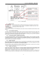
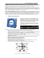
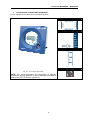
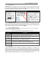
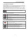
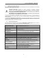
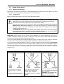
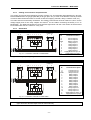
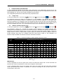
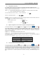
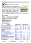
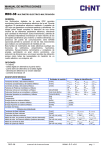
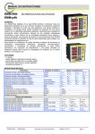
POWER FACTOR REGULATORS
MCE06ADV – MCE12ADV
Instructions Manual
Controllers MCE06ADV – MCE12ADV
-1-
Controllers MCE06ADV – MCE12ADV
Index______________________________________________________________
1
INTRODUCTION AND SAFETY RECOMMENDATIONS ......................................................................... 3
1.1
DELIVERY SPOT CHECK .................................................................................................................................. 3
1.2
STARTING SCREEN ......................................................................................................................................... 4
1.3
DEFINITIONS .................................................................................................................................................. 4
1.3.1
Four quadrant regulators...................................................................................................................... 4
1.3.2
FCP program (FAST Computerized Program). .................................................................................... 4
1.3.3
Stages and steps .................................................................................................................................... 4
1.3.4
Stages ratio program............................................................................................................................. 4
2
GENERAL CHARACTERISTICS ................................................................................................................... 5
3
FRONT PANEL: SCREEN AND KEYBOARD .............................................................................................. 6
3.1
DISPLAY SCREEN............................................................................................................................................ 7
3.2
MEASURED PARAMETERS............................................................................................................................... 7
3.3
ERRORS AND ERROR MESSAGES................................................................................................................... 7
3.4
ALARM RELAY ............................................................................................................................................... 7
3.5
REGULATOR STATUS AND KEY FUNCTIONS .................................................................................................... 8
3.5.1
Key functions in normal RUN status. .................................................................................................... 8
3.5.2
Key functions in SET-UP status. ........................................................................................................... 8
4
INSTALLATION AND START UP .................................................................................................................. 9
4.1
TECHNICAL CHARACTERISTICS ...................................................................................................................... 9
4.2
DEVICE INSTALLATION ........................................................................................................................ 10
4.2.1
Mechanical Installation....................................................................................................................... 10
4.2.2
Connections ......................................................................................................................................... 10
4.2.3
Cabling cross sections and protections ............................................................................................... 11
4.2.4
Schematics ........................................................................................................................................... 11
5
CONFIGURABLE PARAMETERS ............................................................................................................... 12
5.1
5.2
5.3
5.4
5.5
5.6
5.7
5.8
6
SET-UP MENU AND PROCEDURE. ............................................................................................................ 14
6.1
6.2
7
TARGET COSϕ .............................................................................................................................................. 12
SMALLER AVAILABLE CAPACITOR STEP ....................................................................................................... 12
C/K PARAMETER CALCULATION................................................................................................................... 13
STAGE’S CONFIGURATION OF PF CORRECTION EQUIPMENT (CONFIGURATION PROGRAM)........................... 13
CONNECTION AND RE-CONNECTION TIME SETTINGS: ................................................................................... 13
SELECTION OF THE NUMBER OF STAGES. ...................................................................................................... 14
V,I PHASE ANGLE SETTING. .......................................................................................................................... 14
PROGRAMMING THE CT RATED CURRENT (PRIMARY). ................................................................................ 14
HOW TO ACCESS THE SET-UP MENU.............................................................................................................. 14
NAVIGATION SCHEMATIC. ............................................................................................................................ 15
RUN STATUS ................................................................................................................................................... 16
7.1
7.2
FUNCTIONS OF THE DEVICE IN NORMAL RUN MODE. ................................................................................... 16
MCEXXADV BEHAVIOUR IN ALARM MODE .............................................................................................. 17
8
MAINTENANCE .............................................................................................................................................. 17
9
TECHNICAL SERVICE .................................................................................................................................. 17
-2-
Controllers MCE06ADV – MCE12ADV
1
INTRODUCTION AND SAFETY RECOMMENDATIONS
INTERNATIONAL CAPACITORS, S.A. would like to thank you for showing your trust by choosing one of
our MCExxADV series regulators. These units are constructed with the latest state-of-the-art technology,
including a powerful processor to calculate the optimum algorithms for achieving the best compensation
of cosφ.
The units comply with the Electrical Safety Standard EN 61010, in accordance with the requirements of
the Low Voltage Directive (LVD) 73/23/EC and EMC Directive (2004/108/EC) and, therefore, they are
certified to carry the CE mark.
This user manual describes the operation of the MCExxADV series regulators and shows the user the
procedures required to install, commission and operate the units.
SAFETY
CAUTION!
DANGER!
The installation and maintenance of the unit must be performed by duly trained and
authorised staff and in accordance with the national and international standards. Any
inappropriate manipulation or use of this equipment out of the conditions specified by the
manufacturer may involve serious dangers to the user.
Before performing any maintenance operation on the controller and associated PF
compensation equipment, be sure to disconnect the main switch. After disconnecting the
switch, wait at least 5 minutes to ensure that the capacitors are totally discharged.
During the installation, maintenance or commissioning of equipment regulated by a MCExxADV unit, the
following safety precautions must be observed:
Before connecting the equipment make sure that the earth terminals have been properly connected.
A defective earth connection may cause a wrong operation of equipment and involves a danger of
electric shock to the user or system operator.
Maintenance must be performed taking the necessary precautions to avoid electrocution and electric
shock. Ensure that the unit has been disconnected and wait the necessary time to ensure that the
capacitors are totally discharged before any maintenance action. We recommend the use of safety
goggles and gloves when cabinet doors are open and protection covers removed.
If a PF compensation unit is connected to mains and capacitors are accidentally connected without
load, a resonance may occur. In such condition voltage harmonics may be amplified, cause
overvoltage and damage the compensation unit and other equipment connected to the mains.
The start-up and interruption procedures indicated in the manual must be followed to avoid
damaging the PF equipment and/or other equipment connected to mains.
The adjustment or replacement of components or parts of the unit must be made with original
replacement parts and in accordance with the procedures described in the corresponding instruction
manual.
1.1
Delivery spot check
After unpacking the equipment check the following points:
Check that equipment has not suffered any damage during transport.
The equipment corresponds to type you ordered. (See label at the rear face, fig. 1.1)
Check that the characteristics in the label are suitable for the site where the regulator has to be
installed. (Supply voltage and frequency, measuring range, etc.)
Follow the instructions in section 3 for installation and set-up.
If you may observe any anomaly during the installation or set-up, contact with INTERNATIONAL
CAPACITORS, S.A. technical service.
-3-
Controllers MCE06ADV – MCE12ADV
Fig. 1.1.- Rear face label
1.2
Starting screen
When the MCExxADV is started (just after supply connection) the screen shows
a code indicating the device version. It’s important to indicate this code in case
of reporting any device fault or error.
1.3
Definitions
In this section we shall give several definitions which will be useful to understand several sections of this
manual
1.3.1
Four quadrant regulators
This term is used to describe the regulators which are able to perform measure and control, either if the
active power flows from the utility to the customer network (the common case of a consuming facility) or if
it flows in the reverse sense. The later is the case of facilities containing power generation equipment
which export some amount of generated power to the utility.
1.3.2
FCP program (FAST Computerized Program).
The units having FCP program, control the switching of capacitor stages in order to minimize the number
of switching operations to reach the required PF compensation. Moreover, the program assigns the
capacitor stages to be connected or disconnected using a FIFO criterion (FIFO= First IN, first OUT), that
way the times of use of all stages are equalized.
1.3.3
Stages and steps
We must distinguish between these two terms. In this manual we call STAGE to each of the capacitor
groups that constitute the PF correction unit. The capacitor stages in PF correction equipment may have
all the same power or not, as explained in the following paragraphs.
The term STEP is used to describe the minimum fraction of reactive power in which the PF correction
equipment is divided. Usually this is the power of the lower stage.
1.3.4
Stages ratio program
Powers of successive capacitor stages in PF correction equipment generally follow certain patterns called
stages ratio program or simply “Program”. The stages program indicates the relationship between the
different capacitor stage powers. Most common stages ratio programs are the as follows:
Program 1:1:1. All capacitor stages have the same rated power (kvar). For instance, a 5-stage unit of
100 kvar would be formed by 5 equal stages of 20 kvar and would be described as a unit of (5 x 20) kvar.
-4-
Controllers MCE06ADV – MCE12ADV
Program 1:2:2. All capacitor stages from the second and up have a rated power (kvar) which is twice the
rated power of first stage. For instance, a 5-stage unit of 180 kvar would be formed by a first stage of 20
kvar and 4 equal stages of 40 kvar, and would be described as a unit of (20 + 4 x 40) kvar.
Program 1:2:4. The rated power of the second stage is twice the rated power of the first stage and the
rated power of third stage and up is 4 times the power of the first stage. For instance, a 5-stage unit of
300 kvar would be formed by a first stage of 20 kvar, a second stage of 40 kvar and 3 equal stages of 80
kvar, and would be described as a unit of (20 + 40 + 3 x 80) kvar.
Other switching programs. Other switching programs are also commonly available, like 1:2:2:4 or
1:1:2:2, etc. Abbreviated designation form, as can be deduced from previous cases, consists of a
sequence of numbers giving the relationship between the different stage powers (kvar), and the first
stage power, which value is taken as unit (1 ). The successive stages will be designated by 1, or 2 or 4,
etc. meaning that the kvar ratio of such stages with regard to first stage are equal, twice, four times, etc.
2
GENERAL CHARACTERISTICS
The power factor regulators, of types MCE06ADV and
MCE12ADV measure the cosφ (sometimes called
Displacement Power Factor, DPF) in a supply network
and control the connection and disconnection of power
capacitors in order to regulate such parameter.
The difference between the two types is the number of
output relays, which determines the number of stages
that they can control.
Type
MCE06ADV
MCE12ADV
Maximum Nr of
output relays
6 relay outputs
12 relay outputs
Among the most important features of this PF regulator series we can stand out the following:
-
FCP regulation system, which minimizes the number of switching operations.
Wide choice of switching programs: 1:1:1, 1:2:2, 1:2:4 , 1:1:2:2, etc. which allows the split up of
the total power into up to 31 steps in MCE06ADV or up to 79 steps in MCE12ADV.
Four quadrants control (see fig.2.1) , display of the connected stages, of cosφ and active and
reactive power signs (inductive
or capacitive )
LCD display screen with three seven segments characters plus 20 icons to sign up the different
possible working conditions.
Regulator set-up with only three keys and without disconnecting the device from the supply.
Multiple supply frequency range, either 50 or 60Hz
Main electrical parameters displayed during RUN mode
Easy panel mounting, without the need of tools.
+1
+1
Front frame size (144 x 144 mm) according to DIN 43 700 (panel hole 138 x 138 mm)
Measurement and power supply in one single input.
Four quadrant regulation (suitable for installations importing or exporting energy)
Fig. 2.1.- Power signs in four quadrants measurements
-5-
Controllers MCE06ADV – MCE12ADV
3
FRONT PANEL: SCREEN AND KEYBOARD
The PF regulator’s front panel shows the following items:
Front Screen
Configurable Parameters
Measured Parameters
Navigation keys
Fig. 3.1.- Front cover and screen
NOTE: The set-up procedure, the description of different
parameters and the different control modes are described in
detail in the SET-UP section (section 6)
-6-
Controllers MCE06ADV – MCE12ADV
3.1
Display screen
MCExxADV devices are equipped with a 3 digits x 7 segments LCD screen. The screen has also a set of
icons, which provide information about the regulator status. The main indications are: cosφ value,
reactive power sign (
for lagging or inductive PF and
for leading or capacitive PF), connected
stages and measurement of different parameters (see section 3.2)
Icons
Screen and LED
Icons Indications
: Lagging or inductive
power indication
: Leading or capacitive
power indication
In normal working conditions, RUN
LED (red) is ON and
cursor
points to the parameter being
displayed (Left column list)
The RUN LED (red) is ON in
normal working conditions
In SET-UP mode, the RUN LED is
OFF, the
cursor is blinking and
pointing to the parameter being
configured (Right column list).
The x10 ⊗ Ip LED shows
that the reading of current or
max. current has to be
multiplied by 10
Symbols indicating the stages
which are connected (only in RUN
mode)
3.2
Measured parameters
When the instrument is in normal RUN mode, the following parameters can be displayed: cosϕ, mains
current, THD of both mains current and mains voltage. The instrument can also display the maximum
values of mains current and voltage since the last parameters clear. The parameter being displayed can
be selected with the navigation keys and is indicated by the cursor.
3.3
Errors and ERROR messages
In case that the regulator detects a possible error, the front screen shows an error code. The possible
error codes are listed and explained in table 3-1.
Table 3-1: Possible errors and messages displayed on the screen
ERROR
message
Description
Load current below the threshold current, or current transformer (CT) not
connected. The threshold is 0,1A at the secondary side of CT
Overcompensation. The regulator detects that some stages should be
disconnected but all the stages are already disconnected.
Under-compensation. The regulator detects that some stages should be
connected and all the stages are already connected.
Overcurrent. The measured current exceeds the rated current by a + 20%.
(Rated current is considered to be the CT primary rated current)
Overvoltage. The measured voltage exceeds the rated voltage by a +15%.
3.4
Alarm relay
In case that the number of stages configured in a MCE06ADV or MCE12ADV , is less than 6 or 12
respectively, the relay number 6 or 12 is automatically configured as alarm relay. The relay remains
connected in absence of alarm (positive safety) and disconnects in case that one or more of the errors
listed in section 3.2 occur. Notice that the absence of supply voltage will always be detected as an alarm
condition. The alarm relay has a delay of 10s in case of Over-compensation and Under-compensation,
but the operation is instantaneous (delay < 1s) in case of Over-voltage and Over-current.
-7-
Controllers MCE06ADV – MCE12ADV
3.5
Regulator status and key functions
MCExxADV regulators have two possible status.
Normal or RUN Status: This is the normal working status of the regulator. In such status the device
measures and displays the cosϕ of the loads and automatically regulates the connection and
disconnection of capacitors in order to compensate according to programmed target value. The regulation
depends on several parameters configured during the starting set-up process.
Set-up or adjustment status: This status allows the configuration of the device. Push the key
for a
time >1s to enter the set-up status mode. This will stop the automatic PF regulation, will cause the
progressive disconnection of connected stages and once disconnected will allow the set-up of the
regulator.
The navigation keys have different functions depending on the regulator status.
3.5.1
Key functions in normal RUN status.
Key to enter set-up mode: After a long push (> 1s) of this key, the device will enter
the set-up mode, and will accept configuration changes.
Manual connection of capacitor stages: If this key is pushed for more than 1s, the
regulator starts connecting new steps in a sequential mode, respecting the adjusted
connection times, ton
Manual disconnection of capacitor stages: If this key is pushed for more than 1s,
the regulator starts disconnecting steps in a sequential mode, respecting the adjusted
disconnection times, toff
3.5.2
Key functions in SET-UP status.
Long Push (>1s): This is to initiate or exit the set-up mode. Exiting the set-up mode
with a long push (>1s) will automatically save the changed parameters. Exiting with a
short push will not save the changes.
Long Push (<1s): This is used to initiate or exit the different set-up sub-menu options
(different configurable parameters). Warning! The new programmed values are not
saved unless a long push of this key (>1s) is used to exit the set-up menu.
Upwards navigation in the menu options available in the set-up menu.
Increment of numerical values inside the set-up sub-menus.
Downwards navigation in the menu options available in the set-up menu.
Decrement of numerical values inside the set-up sub-menus.
Change the digit to be edited in case of numerical values with more than one digit.
-8-
Controllers MCE06ADV – MCE12ADV
4
INSTALLATION AND START UP
This section contains information instructions and warnings that the user must follow by its own security
and to ensure safe operation of the device.
WARNING! MCExxADV regulators are usually connected to equipment containing
capacitors, which remain charged after removing supply voltage. To avoid risk of electric
shock, you must wait at least 5 minutes between the disconnection of the equipment
and handling of the internal components thereof.
Any handling or use of equipment in different way or conditions to that specified by
the manufacturer, may compromise the user safety.
In case that some damage or deterioration signs are detected in the device or a wrong operation is
observed, disconnect the supply voltage and contact INTERNATIONAL CAPACITORS,S.A. authorized
technical service.
To safely use the MCExxADV and MCExxADV it is important that people installing it or handling it follow
the usual safety precautions stated in the LV or MV Electrical Code Rules of each Country as well as the
different warnings stated in this instruction manual.
4.1
Technical Characteristics
The main technical characteristics of every particular MCExxADV and MCExxADV device are printed in
the rear label (see fig. 1.2) and are also summarized in the following table.
Supply and measuring circuit
voltage (Terminals C-D)
Supply Cables
Supply circuit protection
Current measurement circuit.
(Terminals A-B)
Cables for the current
measurement circuit (CT
secondary side)
Current margin
Measurements precision
cosϕ
ϕ setting margin
Power Consumption
Screen
Output: Relay contacts
Cabling and protection of relays
output.
Alarm relay
Reference standards
Safety and Insulation class
Protection degree
Environment admissible
conditions
Control system
480, 400, 230 o 110 VCA ; +15% -10% ; 45-65 Hz , (see label)
Connect preferably to phases L2-L3.
2
Cross Section 1,5mm
By means of a 0,5 to 2A fuse (gl type)
External Current Transformer (CT). Current ratio In /5. To be placed
preferably in phase L1.
2
Minimum cross section : 2,5mm . If cable length between regulator
2
and CT must exceed 25m, increase the cross section by 1mm every
10m or use a CT with a higher primary rated current.
0,1 to 5 A (maximum overload +20%)
Voltage and Current: 1%; cosϕ : 2% ± 1 digit
0,85 ind. A 0,85 cap. Default setting: 1
6 VA (all relays OFF) ; 9,5VA (12 relays ON)
1 line x 3 digits x 7segments + 20 icons
Working voltage: 250 VCA, Admissible current: 10 A, AC1.
2
Minimum cables cross section: 1,5mm , Protect by means of a
circuit breaker 6A, curve C or fuse 6A, gl type
In case that not all the relay outputs are used to drive the capacitors,
the highest number relay is by default configured as alarm relay.
EN 61010, EN 61000-3-2, EN 61000-3-3, EN 50081-2, EN 50082-1,
EN 50082-2, EN 61000-4-2, EN 61000-4-4, EN 61000-4-8,
EN 61000-4-5, EN 61000-4-11 , UL 94
Installation Category III. Protection against electrical shock with
double insulation (class II ), according to EN 61010-1
IP51 (device mounted in panel front)
IP30 (device case) according to EN-60529
Temperature: -20ºC a +60ºC; Relative humidity: max. 95% (without
condensation). Max. altitude: 2000m
FCP (Program which minimizes the number of operations)
-9-
Controllers MCE06ADV – MCE12ADV
4.2
DEVICE INSTALLATION
4.2.1
Mechanical Installation
Mechanically, the device is intended to be mounted attached to the front door of the cabinet. The fitting
+1
+1
hole must be according to DIN 43 700, (dimensions 138 x138 mm).
4.2.2
Connections
Before connecting the supply to the device check the following items:
The installation and maintenance of the device must be carried out by specialised and dully
trained staff, according to National Electric Codes and Rules and International Standards
All the connections must be at the inner part of a protection cabinet.
Notice that when the device is connected to supply, the voltage at certain terminals can be
hazardous and cause electric shock in case of contact. Opening the electrical cabinet or
removing certain covers can compromise the user safety and should only be done by
qualified and authorized staff.
The MCExxADV devices are used together with capacitor banks, which can remain charged
after supply disconnection. In order to avoid shock hazard, wait during 5 minutes after supply
disconnection before any manipulation inside the equipment cabinet.
MCExxADV devices require current sensing of the installation. A current transformer (CT) must be
installed externally to perform this function. Usually the current ratio of the CT is In / 5 A, where In must
be at least 1,5 times the maximum expected load current.
The CT must be installed at the incoming supply line (point of coupling of the user), so that it measures
the total current of all the loads, including also the compensation capacitor bank (see fig. 4.1)
The CT should be installed preferably in phase L1, while the voltage measuring terminals of MCExxADV
should be connected to phases L2 and L3 (see schematics in figs. 4.2 and 4.3). It’s important to respect
the connection senses of P1-P2 and S1-S2 shown in the above mentioned figs, otherwise the phase
difference will have to be corrected by adjusting the device according to set-up procedure indicated in
paragraph 5.17.
RIGHT C
The CT
curre t
ba !
I case
that the
ECTI
WR
easures the wh e
f ads
capacit r
f a fu cti chec
CT is t sh rtcircuited
GC
If CT is p aced i this p siti "
E f the CAPACIT R
STAGES WI%% C
ECT!
The equip e t d es t regu ate
pr per y
ECTI
If CT is p aced i this p siti
A%% THE CAPACIT R STAGES
WI%% C
ECT!
WAR I G! This situati
ay
cause verc pe sati
res a ce a d vercurre t
Fig. 4.1.- Placement of current transformer (CT)
- 10 -
S
Controllers MCE06ADV – MCE12ADV
4.2.3
Cabling cross sections and protections
The supply circuit must be protected by means of fuses or a circuit breaker sized between 0,5 and 2A.
Recommended fuses are gl type (IEC 269) or M type (IEC 127). A main circuit breaker must be provided
in order to allow the disconnection of control circuits from supply (controller, relays, contactor coils, etc.)
2
The main switch must be easily accessible. The cabling cross section must be minimum 1,5mm for the
2
voltage supply and for the relay outputs and 2,5mm for the cables connecting secondary of CT to
MCExxADV . For distances between CT and controler higher than 10m the cross section of the last must
2
be increased at a rate of 1 extra mm every 10m.
4.2.4
Schematics
MCE06ADV
A
B
S1
COM 1
2
3
4
5
6
S2
P1
SUPPLY AND MEASURE
TERMINALS
C
D
0
RELAYS
P2
V
C1..C6
Fig. 4.2.- Connection schematic for MCE06ADV
Nº
Terminals functions
A
B
COM
1
2
3
4
5
6
C
D
Current input S1
Current input S2
Relays common
Relay Output 1
Relay Output 2
Relay Output 3
Relay Output 4
Relay Output 5
Relay Output 6
Supply/Measure Input 0V
Supply/Measure Input(*)
Nº
Terminals description
A
B
COM
1
2
3
4
5
6
7
8
9
10
11
12
C
D
Current input S1
Current input S2
Relays common
Relay Output 1
Relay Output 2
Relay Output 3
Relay Output 4
Relay Output 5
Relay Output 6
Relay Output 7
Relay Output 8
Relay Output 9
Relay Output 10
Relay Output 11
Relay Output 12
Supply/Measure Input 0V
Supply/Measure Input(*)
(*) Rated voltage depending on type. See device label
MCE12ADV
SUPPLY AND MEASURE
TERMINALS
A
S1
P1
B
COM 1
2
3
4
5
6
S2
C
0
P2
COM
RELAYS
C1..C6
RELAYS
C7..C12
7
8
9
D
V
10 11 12
Fig. 4.3.- Connection schematic for MCE12ADV
(*) Rated voltage depending on type. See device label
WARNING! For MCE12ADV devices (12 relay outputs) the connection between COM terminals in the
upper and lower terminal strips must be done externally.
- 11 -
Controllers MCE06ADV – MCE12ADV
5
CONFIGURABLE PARAMETERS
In order to adapt the regulator to the loads, certain parameters of the MCExxADV must be set-up. The
programmable parameters, the required settings and the set-up procedure are explained here below. See
also paragraph 3.5.2 to see how to select the different menu options.
The configurable parameters are listed and shortly explained below.
5.1
Target cosφ
To set-up this parameter, use the keys
until the cursor
points to the option
, then push
The parameter allows the setting of the desired PF in the installation. The regulator will control the
connection of the necessary number of capacitors to get the maximum approach to the target value.
Since the regulation is in a stepwise mode, the regulator will add a new step when the demanded power
is at least 70% of the lower available step power and will remove a step when the excess is also a 70% of
the lower available step power. The cosφ adjustment range is from 0,85 inductive to 0,95 capacitive.
5.2
Smaller available capacitor step
To set-up this parameter, use the keys
until the cursor
points to the option
, then push
This parameter, named C/K, indicates the reactive current supplied by the smaller capacitor step,
measured at the secondary side of the current transformer (CT). Therefore, the setting value depends on
the power of the smaller capacitor step, on the CT ratio and on the supply voltage. Table 5.1 gives the
setting values of C/K for a 400V phase to phase supply for different CT ratios and different values of
smaller capacitor step (kvar). For conditions other than those given in table 5.1, the paragraph 5.13
shows a simple calculation to obtain the C/K value. See also foot NOTE
Table 5-1.- C/K factor according to smaller capacitor power and CT ratio.
CT ratio
(Ip/Is)
150/5
200/5
250/5
300/5
400/5
500/5
600/5
800/5
1000/5
1500/5
2000/5
2500/5
3000/5
4000/5
Smaller capacitor power in kvar, at 400V (*)
2.5
0,12
0,09
0,07
0,06
0,05
5,00
0,24
0,18
0,14
0,12
0,09
0,07
0,06
7.5
0,36
0,27
0,22
0,18
0,14
0,11
0,09
0,07
0,05
10,0
0,48
0,36
0,29
0,24
0,18
0,14
0,12
0,09
0,07
0,05
12,5
0,60
0,45
0,36
0,30
0,23
0,18
0,15
0,11
0,09
0,06
15,0
0,72
0,54
0,43
0,36
0,24
0,22
0,18
0,14
0,11
0,07
0,05
20,0
0,96
0,72
0,58
0,48
0,36
0,29
0,24
0,18
0,14
0,10
0,07
0,06
0,05
25,0
0,90
0,72
0,60
0,48
0,36
0,30
0,23
0,18
0,12
0,09
0,07
0,06
30,0
37,5
40,0
50,0
60,0
75,0
80,0
0,87
0,72
0,58
0,45
0,36
0,27
0,22
0,14
0,11
0,09
0,07
0,05
0,90
0,67
0,54
0,45
0,33
0,27
0,18
0,13
0,10
0,09
0,06
0,96
0,72
0,54
0,48
0,36
0,29
0,19
0,14
0,12
0,10
0,07
0,87
0,72
0,60
0,45
0,36
0,24
0,18
0,14
0,12
0,09
0,87
0,72
0,54
0,43
0,29
0,22
0,17
0,14
0,11
0,90
0,68
0,54
0,36
0,27
0,22
0,18
0,14
0,96
0,72
0,57
0,38
0,28
0,23
0,19
0,14
(*) NOTE: For supply voltages other than 400V the C/K factor obtained from the table must be multiplied by the ratio
(400 / Vsupply)
IMPORTANT! :
If C/K is adjusted too low the system will connect and disconnect steps with a lower threshold and
therefore the number of operations to control the average PF will be higher.
If C/K is adjusted slightly above the required value (10%) the system will react with higher threshold
values and therefore the number of operations to control the average PF will be lower. Wear of PF
compensation is also lower.
- 12 -
Controllers MCE06ADV – MCE12ADV
5.3
C/K parameter calculation
For conditions other than those given in table 5.1 the parameter C/K can be calculated as follows.
The necessary data to perform the calculation are: The power of the smaller capacitor step, Q, the supply
voltage, V and the current transformer ratio, K & K = I prim / I sec .
Where:
I prim is the CT primary rated current (i.e. in a 250/5 CT , the primary rated current is 250A)
I sec is the CT secondary rated current , usually 5A
Then, the smaller step reactive current, IC, can be calculated as:
and the C/K parameter would be
I
C/K = C =
K
IC =
Q
3 .V
Q
3 .K .V
Example: Assume a PF equipment at 500V where the smaller capacitor is rated to 60kvar and the CT
has a ratio 500/5. The calculation would be as follows:
K ratio
K = 500 / 5 = 100
60.1000
Smaller capacitor current
IC =
= 69,28 A
3.500
Ic 69,28
C/K parameter
C/K = =
= 0,69
K
100
5.4
Stage’s Configuration of PF correction equipment (Configuration program)
To set-up this parameter, use the keys
until the cursor
points to the option
, then push
PF correction equipment is constituted by several capacitor stages, which may have different power
ratings. Taking as base the power of the smaller capacitor stage, the powers of the rest of stages can be
given in terms of multiples of the smaller step. Then we could state the configuration (configuration
program) of PF equipment as:
Program 1:1:1… All the stages have the same power in kvar.
Program 1:2:2… The second stage and successive have a power double than the 1st step.
The available programs of MCExxADV regulator are listed in table 5.2. The default factory setting of
MCExxADV devices is 1:1:1:1
Table 5-2.- Available configuration programs for MCExxADV devices
Screen Indication
111
122
124
248
112
5.5
Stage’s configuration
1:1:1:1:1….
1:2:2:2:2….
1:2:4.4:4….
1:2:4:8:8….
1:1:2:2:2….
Connection and re-connection time settings:
To set-up this parameter, use the keys
until the cursor
points to the option
, then push
This parameter sets up the delay times of the device. The setting value, Tc, is the delay time between the
connection or disconnection of successive capacitor stages. The parameter also sets up the called reconnection delay, Tr, which is the minimum time that must elapse between the disconnection of a C stage
and its following connection. The range of Tc settings goes from 4s to999s. Tr is automatically set to 5
times Tc (Notice that Tr is needed to guarantee the capacitors discharge). The default setting of Tc is
10s.
- 13 -
Controllers MCE06ADV – MCE12ADV
5.6
Selection of the number of stages.
To set-up this parameter, use the keys
until the cursor
points to the option
, then push
This setting allows the selection of the number of stages of the PF compensation equipment. Depending
on the device type, MCE06ADV or MCE12ADV we can select up to 6 or 12 stages. If the number of
stages is less than 6 or 12 respectively in MCE06ADV or MCE12ADV the relay number 6 or 12 is
automatically assigned as alarm relay (see paragraph 3.3)
5.7
V,I phase angle setting.
To set-up this parameter, use the keys
until the cursor
points to the option
, then push
During the set-up of this parameter, the screen shows alternatively one of the options T1 to T6 and the
cosϕ.
This parameter permits the adaptation of the regulator to different options of connection of voltage and
current measurement in the three phase system. The default assumed connection is the one shown in
figs. 4.2 and 4.3, i.e., the current transformer placed in phase L1 and voltage measurement between
phases L2 (terminal C) and L3 (terminal D). Sometimes it’s difficult to guarantee this connection or even
check how it is. To adapt to this unknown situations the MCExxADV devices allow the selection of
different options, T1 to T6, as shown in table 5.3. To select the right option during start up, you should
verify that there is load and that the loads are mainly inductive with a cosϕ between 0,7 y 1. In this
situation try the different options until the cosϕ screen shows a value between 0,7 and 1
Table 5-3.- Phase shift options in MCExxADV
Screen
T1
T2
T3
T4
T5
T6
V-I phase shift at
cosϕ
ϕ=1
30º
270º
150º
210º
90º
330º
V measured in phases
CT placed in phase
L3-L2
L3-L2
L3-L2
L3-L2
L3-L2
L3-L2
L3
L1
L2
L3 (P1-P2 or S1-S2 reversed)
L1 (P1-P2 or S1-S2 reversed)
L2 (P1-P2 or S1-S2 reversed)
5.8
Programming the CT rated current (primary).
The set-up of this parameter can be selected at the bottom of the menu options. Use the
keys until
the bottom red LED
is flashing and push
. The display will show the assumed CT primary
current. Set the value according to the CT used to measure installation current. The adjustment range is
from 0 to 999 and with the x10 option allows a rated primary current up to 9990A. By default the
secondary of CT is assumed to be 5A
6
6.1
SET-UP MENU AND PROCEDURE.
How to access the set-up menu.
To access the set-up menu, press the key
for more than 1s (This is designated as long push in table
6.1 , which gives a summary of the set-up procedure). The pointer
starts blinking and points to the
parameter to be adjusted. Select the parameter by means of the keys
After the long push and in case that all the capacitor stages are disconnected, the device jumps to the
set-up status. In case that there are some stages connected, keep the key
pushed while the regulator
disconnects the connected stages sequentially and respecting the programmed delay time. Once all the
stages have been disconnected the device enters the set-up status and allows the adjustment of the
different parameters. A schematic diagram of the set-up menu showing the different navigation paths is
shown in table 6.1. The meanings of the different adjustable parameters have been explained in
paragraph 5.1.
- 14 -
Controllers MCE06ADV – MCE12ADV
6.2
Navigation schematic.
Tabla 6-1.- Menu navigation schematic
Parameter
selection
Device screen display
See
paragraph
Long push
to start set-up
Target cosϕ
Starting screen
5.1
C/K
5.2
5.3
Program
5.4
Delay times
5.5
Nr of stages
5.6
CT phase
5.7
CT primary
current
5.8
! IMPORTANT! :
While the device is in set-up mode, if there isn’t any key pushing for more than 3 minutes, the device
returns automatically to normal RUN mode and none of the previously edited parameters are changed nor
saved. To exit the set-up menu changing the edited parameters, push the key
for more than 1s.
- 15 -
Controllers MCE06ADV – MCE12ADV
7
RUN STATUS
Once the device has been configured according to installation needs it can be set to RUN mode to
regulate the PF of the installation. RUN mode is the default mode after exiting the set-up menu or after
the device start (supply connection followed by a short initialisation period). When the device is in RUN
mode it can reach one of the following status:
a) Normal RUN status (Absence of alarm): In this status the device performs the automatic PF
regulation, connecting and disconnecting the capacitor stages according to installation needs. In
this status the user can access to the measurement of different parameters and can also force
the manual connection or disconnection of capacitor stages as described in paragraph 7.1.
b) Alarm status: If any of the anomalous situations described in paragraph 3.2 occur, the device
jumps to alarm status and displays the error code. Depending on the error type the regulator may
perform the disconnection of all the stages or continue regulating the PF as in normal RUN.
7.1
Functions of the device in normal RUN mode.
In the normal RUN mode the MCExxADV can perform the following functions:
long
long
Manual connection of capacitor stages. Keep the key pushed during more than 1s
and the regulator will sequentially connect the different steps, following the normal
program and respecting the delay time ton set in the set-up procedure
Manual disconnection of capacitor stages: Keep the key pushed during more than
1s and the regulator will sequentially disconnect the different steps, following the
normal program and respecting the delay time toff set in the set-up procedure.
Displaying the number of connected steps: If both keys are simultaneously pushed
the device displays the Nr of connected steps. (Remember the difference between step
and stage described in paragraph 1.1)
short
short
long
MAX
Parameters measurement: Performing successive short pushing of this key (<1s), the
user can travel along several display screens showing the values of the following
parameters: (cos) , cosinus ϕ of the installation ; (I) , mains current; (THD), THD of
mains current; (V) , Mains voltage; (I, MAX), Maximum value of mains current since the
last clear; (V MAX), Maximum value of mains voltage since the last clear. The
displayed parameter is pointed by the cursor
Parameters measurement: Performing successive short pushing of this key (<1s), the
user can travel through the readings of the same parameters described above but in
reverse order.
Start the SET-UP mode: : Performing a long push of this key (<1s), the device jumps
to set-up mode.
Clear MAX values: Performing a long push of this key (<1s) while the cursor is
pointing to MAX , the MCExxADV clears the maximum values of voltage and current
recorded since the last clear.
- 16 -
Controllers MCE06ADV – MCE12ADV
7.2
MCExxADV behaviour in ALARM mode
In case that the MCExxADV detects an error during normal operation (see paragraph 3.2) the screen
displays an error code and the behaviour of the device is as described in table 7-.1.
Table 7-1: MCExxADV behaviour under ALARM conditions
ERROR
message
Description
Possible cause and MCExxADV behaviour
Measured current below
threshold (0,1ª measured at
the secondary side of CT)
Over-compensation. The
controller
demands
for
stages disconnection and
they are all disconnected.
Sub-compensation.
The
controller
demands
for
stages connection and they
are all connected.
Overcurent. The measured
current is 20% above the
rated current (primary of CT)
Posible causes: Baja carga o TC no conectado.
El aparato muestra el LED de RUN y la pantalla con todo
ceros parpadeando y no conecta ningún relé
Possible causes: C/K not properly adjusted
None of the realys will connect.
Overvoltage.The measured
voltage is 15% above rated
voltage.
8
Possible causes: C/K not properly adjusted
All the relays will remain connected, except the alarm relay
if exists (see paragraph 3.3)
Possible causes: C/K not properly adjusted
Alarm relay, if exists, disconnects (see paragraph 3.3)
Although the regulation may be wrong, the device tries to
regulate the PF normally.
Possible causes: Connection to a wrong supply voltage.
Alarm relay, if exists, disconnects (see paragraph 3.3)
Although the regulation may be wrong, the device tries to
regulate the PF normally.
MAINTENANCE
The MCExxADV do not require a special maintenance program. In case that some adjustments or
maintenance might be necessary it must be performed by dully qualified staff and respecting the required
safety procedures.
If any malfunction of the PF compensation equipment or associated protections is detected, the
equipment should be disconnected from mains. Before performing any maintenance repair or update
operation on the controller or associated PF compensation equipment, be sure to disconnect the main
switch and after disconnecting the switch, wait at least 5 minutes to ensure that the capacitors are totally
discharged.
9
TECHNICAL SERVICE
In case of any doubt on the behaviour of the device or in case of malfunction which cannot be solved by
the maintenance staff, contact INTERNATIONAL CAPACITORS, S.A. technical service:
INTERNATIONAL CAPACITORS, S.A.
c/ Vallés, 32 – Pol. Ind. Can Bernades
08130 – Santa Perpetua de Mogoda (Barcelona) SPAIN
Tel. (+34) 935 747 017 – Fax: (+34) 935 448 433
E-mail : [email protected]
Web: www.lifasa.com
- 17 -