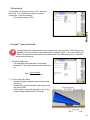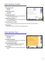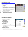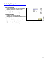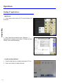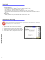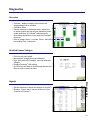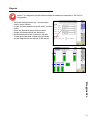
1
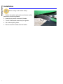
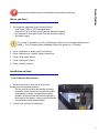
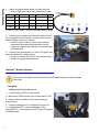
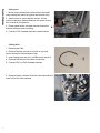
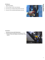
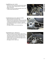
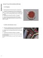
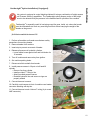
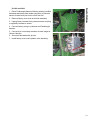
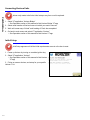
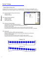
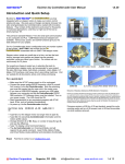
Horizon™
Horizon Manual
09062201b
headsight.com • 574.546.5022
Installation
About Headsight
Headsight Contact Info
Headsight, Inc.
4845 3B Road
Bremen, IN 46506
Phone: 574-546-5022
Fax: 574-546-5760
Email: [email protected]
Web: www.headsight.com
Technical Assistance
Phone: 574-220-5511
About this Manual
How to use this manual
For new installations, follow all applicable instructions in each of the numbered sections (1, 2, etc) in the
order that they are presented in this manual. The information in the lettered appendices (A, B, etc) is for
service or advanced settings which you will not need for most installations, but may want to reference in
the future.
This icon designates information of which
you should take note.
This icon indicates a special tool needed
for a given task.
This icon designates an important
instruction.
Disclaimers
Headsight®, Horizon™, Pinpoint™, Insight®, Foresight®, Feathersight® and Truesight® are trademarks
of Headsight, Inc. All other trademarks are property of their respective owners.
Suggestions
If you have any suggestions to improve this manual –please call 574-546-5022 or email info@headsight.
com.
Headsight’s products are protected by one or more of the following US Patents 6202395,
6833299, 7310931, 7647753 and other patents pending.
Copyright Headsight, Inc. 2014
i
Installation
ii
Table of Contents
About Headsight��������������������������������������������������������������������������������������������� i
About this Manual������������������������������������������������������������������������������������������� i
Installation�������������������������������������������������������������������������������������������������� 1
Before you Start������������������������������������������������������������������������������������������ 2
Installation on Head������������������������������������������������������������������������������������� 2
Control Box and Main Harness����������������������������������������������������������������������� 2
Horizon™ Header Options������������������������������������������������������������������������������� 3
Geringhoff����������������������������������������������������������������������������������������������� 3
Drago����������������������������������������������������������������������������������������������������� 4
Capello��������������������������������������������������������������������������������������������������� 6
Shelbourne���������������������������������������������������������������������������������������������� 8
Truesense+���������������������������������������������������������������������������������������������� 8
Installation on Combine��������������������������������������������������������������������������������� 9
Installing Horizon Bridge����������������������������������������������������������������������������� 9
Horizon™ Power Wire Installation (CNH only)����������������������������������������������������11
Feathersight® Option Installation (if equipped)��������������������������������������������������12
Connecting Horizon Units������������������������������������������������������������������������������15
Initial Setup����������������������������������������������������������������������������������������������15
Calibration������������������������������������������������������������������������������������������������16
Horizon™ Settings���������������������������������������������������������������������������������������17
2 Sensor Tilt vs 4 Sensor Tilt������������������������������������������������������������������������17
Tilt Sensitivity�����������������������������������������������������������������������������������������18
Foresight® - Gain (Corn Heads)����������������������������������������������������������������������18
Feathersight® - HP Balance (Grain Heads)��������������������������������������������������������19
Header App Settings - Geringhoff���������������������������������������������������������������������20
Select header model����������������������������������������������������������������������������������20
Set shaft speed alarms��������������������������������������������������������������������������������20
Show shaft speed alarm������������������������������������������������������������������������������20
Show deck plate position�����������������������������������������������������������������������������20
Show maintenance reminder������������������������������������������������������������������������20
Header hours�������������������������������������������������������������������������������������������20
Header App Settings - Drago ��������������������������������������������������������������������������20
Set shaft speed alarms��������������������������������������������������������������������������������20
Show shaft speed alarm������������������������������������������������������������������������������20
Show maintenance reminder������������������������������������������������������������������������20
Header hours�������������������������������������������������������������������������������������������20
Header App Settings - Capello�������������������������������������������������������������������������21
Set shaft speed alarms��������������������������������������������������������������������������������21
Show shaft speed alarm������������������������������������������������������������������������������21
Show deck plate position�����������������������������������������������������������������������������21
Show maintenance reminder������������������������������������������������������������������������21
Header App Settings - Shelbourne��������������������������������������������������������������������21
Set min/max rotor lube speeds���������������������������������������������������������������������21
Show rotor speed alarm������������������������������������������������������������������������������21
Speed drop factor��������������������������������������������������������������������������������������21
Show auger speed alarm�����������������������������������������������������������������������������21
Set minimum auger speed���������������������������������������������������������������������������21
Show maintenance reminder������������������������������������������������������������������������21
Header App Settings - Truesense+��������������������������������������������������������������������22
Select steering system��������������������������������������������������������������������������������22
Steering Sensitivity������������������������������������������������������������������������������������22
Crop Detect Threshold��������������������������������������������������������������������������������22
Center Calibration�������������������������������������������������������������������������������������22
Operation���������������������������������������������������������������������������������������������������23
Finding VT applications��������������������������������������������������������������������������������23
John Deere ���������������������������������������������������������������������������������������������23
CaseIH and New Holland�����������������������������������������������������������������������������23
Ag Leader Integra�������������������������������������������������������������������������������������24
Operation�������������������������������������������������������������������������������������������������25
Advanced Info����������������������������������������������������������������������������������������������26
Updating Software���������������������������������������������������������������������������������������26
Updating with Horizon™ App������������������������������������������������������������������������26
Updating with USB������������������������������������������������������������������������������������26
Status Light�����������������������������������������������������������������������������������������������27
Wifi Channels and Naming�����������������������������������������������������������������������������27
Diagnostics�������������������������������������������������������������������������������������������������28
Overview��������������������������������������������������������������������������������������������������28
Detailed Sensor Voltages�������������������������������������������������������������������������������28
Signals�����������������������������������������������������������������������������������������������������28
Errors�����������������������������������������������������������������������������������������������������29
Pinpoint���������������������������������������������������������������������������������������������������30
FCC and IC Compliance Statements���������������������������������������������������������������������31
STATEMENT OF LIMITED WARRANTY �����������������������������������������������������������������32
iii
Installation
Installation
Before working under header always:
1. Perform all combine and header manufacturer safety
precautions for servicing header.
2. Insert stop to prevent movement of header.
3. Turn off combine and remove key from ignition.
4. Set combine parking brake.
5. Disconnect all drive shafts from the header.
1
Before you Start
Installation
Complete the installation portion of the header manual before continuing.
1. Do you have a supported Virtual Terminal Screen?
• John Deere - 2630 or GS3 CommandCenter
• CaseIH Pro 700 (must have Virtual Terminal Software installed)
• NH Intellivew IV (must have Virtual Terminal Software installed)
• Ag Leader Integra
If you need VT software for a CIH or CNH display, contact your local dealer and have them
install it. The VT software allows Headsight’s Horizon to appear on a VT display.
2. Follow “Installation on Head” specific instructions.
3. Follow “Instruction on Combine” specific instructions.
4. Follow “Initial Setup” section.
5. Follow “Calibration” section.
6. Follow “Settings” sections.
Installation on Head
Control Box and Main Harness
1. Mount Horizon box to back side of head, left of
feederhouse with supplied hardware.
• The box must be mounted horizontally on header
• Orientation of the Horizon box is critical for header
angle display for Drago, Geringhoff and Capello
headers, the box must be mounted flat against the
back panel of the header. Using a mounting bracket
is acceptable for other header brands.
2. Connect main harness to Horizon box.
2
Installation
3. Connect individual sensor wiring to Horizon harness.
• Sensor location as viewed from the operator’s seat
2 Sensor
3 Sensor
4 Sensor
5 Sensor
Left Left Center Center Right Center Right
X
X
X
X
X
X
X
X
X
X
X
X
X
X
L
LC
C
RC
*L-Left, LC-Left Center, C-Center, RC-Right Center, R-Right
4. If combine has a harness that mounts to back of head,
mount supplied harness bracket on head and mount main
header harness connector in bracket.
• All others, remove factory harness form existing
single point latch plate and replace with Horizon
harness or install Horizon harness in provided single
point latch plate.
5. If Horizon main harness has Y111 and Y112 pigtail, wire
lights as described in Header manual.
• All others, connect other half of main Horizon wiring
harness to original header harness.
Horizon™ Header Options
This section is for header specific options to control header functions or display header
information.
Geringhoff
Folding and ICF (2012 and Newer)
1. Connect Y904 to Y903 of main harness.
2. Make sure HT9202 resistor pack is connected to Y130.
3. Route harness to header control valves following
existing wiring.
4. Connect Headsight’s X1 to Geringhoff’s harness X1.
5. If equipped with ICF, connect Headsight’s X2 to
Geringhoff’s X2. If not equipped with ICF leave Headsight’s
X2 disconnected.
3
R
Installation
6. Connect Y1-5 connectors as follows
• Y1 to Geringhoff deck plate valve wiring
• Y2 to Geringhoff fold valve wiring
• Y3 to Geringhoff lock pin valve wiring
• Y4 to Geringhoff ICF fore and aft valve wiring
• Y5 to Geringhoff ICF up and down valve wiring
Rigid (2012 and Newer)
1. Connect Y904 to Y903 of main harness.
2. Connect Y412 to mating connector at header connection
point.
Folding and Rigid (2011 and older)
1. Connect Y904 to Y903 of main harness.
2. Connect Y412 to mating connector at header connection point.
3. For folding heads only connect Y122 to wire coming off of folding solenoid valve.
Drago
Shaft speed
1. Connect Y904 to Y903 of main harness.
2. Drill a 3/4 inch diameter hole through the back of the
head in the location shown.
3. Align the hole so the wire comes into gusset “A”.
A
4
Installation
4. Install a grommet in the hole.
5. Feed the sensor wire down the channel from the
Horizon box and through the grommet.
6. Connect the speed sensor wiring to the adapter harness
Y193.
7. Use zip ties to secure the wire and harness.
8. Bolt the sensor bracket to the gusset.
9. Set 1/8 inch minimum clearance distance between the
sensor tip and the hex shaft at its high point.
10.Zip tie the sensor wire inside the gusset so it cannot
come in contact with the shaft “B”.
5
Installation
Capello
For all Capello Header Options
1. Connect Y904 of adapter to Y903 of Horizon main
harness.
Deck Plate Sensor
1. Bolt sensor body to header gusset one row left of
center using 5/16x3/4 bolts.
2. Remove bolt “A” from deckplate adjustment arm.
3. Discard washer and replace with bracket “B”.
• Replace bolt “A” being careful to align it in its original
place so the end of the bolt is in the same detent on
the cross rod.
A
B
4. Connect the 10ft extension wire to the pigtail on the
sensor.
5. Route the wire toward the back of the header being
careful to zip tie it away from the main shaft.
6. Route the wire along the hydraulic lines under the
header to the left of the feederhouse and then up the back
of the header.
7. Connect wire to connector Y211 on the adapter harness.
6
Installation
Shaft speed
1. Mount sensor bracket inline with center of hex shaft
using existing bolt (mount on gusset near Horizon box).
2. Attach sensor to mount bracket and set 1/8 inch
minimum clearance distance between the sensor tip and
the hex shaft at its high point.
3. Route speed sensor wire back toward Horizon box
following existing hoses and wiring.
B
4. Connect Y193 of adapter harness to speed sensor.
Folding Head
1. Remove cap Y540.
2. Remove Deutsch pin lock from inside of cap, and
remove white pins from backside of cap.
3. Insert Orange wire into pin 1 and Black wire into pin 2.
4. Reinstall Deutsch pin lock inside of connector.
5. Connect Y541 to Y540 of adapter harness.
6. Remove factory connector from fold valve solenoid and
install Y49 to fold valve solenoid.
7
A
Auger Rotor Speed
1. Connect Y904 to Y903 of main harness.
2. Connect Y191 to existing mating header connector.
3. Connect Y192 to existing mating header connector.
Installation
Shelbourne
Truesense+
Truesense+ (for use with JD RowSense)
1. Connect extension harness from crop sensor to Y703.
• Be sure to setup and calibrate as directed later in this
manual
8
Installation
Installation on Combine
Installing Horizon Bridge
1. Connect bridge harness to Horizon bridge.
2. Connect bridge harness to combine.
Ag Leader Integra Monitor
• Follow Ag Leader harness from display to the 4 pin
Deutsch and 3 Pin Weather Pack connector
• Connect bridge harness in line at connectors
• Place Bridge on cab floor or in a safe location
John Deere S-series - GS3 Command Center/2630
• Remove cup holder insert
• Connect Y902 to Horizon bridge
• Connect Y936 to diagnostic connector in cup holder
• Connect Y569 to Y570
• Place bridge into cup holder and reinstall cup holder
John Deere 70-series
• Connect Y902 to Horizon bridge
• Connect Y936 to diagnostic connector in right rear
lower cab corner
• Connect Y569 of HT9411 to Y570 of HT9306
• Connect HT9306 to cab powerstrip
• Set bridge on floor in cab corner
9
Installation
CaseIH X230 new cab - Pro700
• Disconnect 16 pin connectors under armrest console
and connect Horizon bridge harness in series with
factory connectors
• Bridge can be set in the right rearward corner of cab
on floor under electronics cover
CaseIH x230 old cab, x120, and x010 - Pro700
• Open armrest door and remove tray
• Disconnect 12 pin connectors in armrest console and
connect Horizon bridge harness in series with factory
connectors (sometimes this connector is hanging
just outside hole in bottom of armrest console - route
back into console)
• Set bridge inside arm rest and reinstall tray
New Holland CR (5v) - Intelliview IV
• Disconnect white 12 pin connectors under armrest
console and connect Horizon bridge harness in series
with factory connectors (make sure color of wires
match the machine wire colors and location, some
machines have two connectors and bridge will only
work in correct connection)
• Set bridge on floor in cab corner
10
Installation
Horizon™ Power Wire Installation (CNH only)
For CIH Flagship
1. Remove plastic shield from left side of feederhouse.
2. Connect 3 pin triangular plug in-line at feeder speed
sensor (Y313 and Y314) on upper left side of feederhouse.
3. Route power wire along existing wiring to main header
connector.
4. Unscrew rear of header connector on combine.
5. Remove white plug from rear of pin 29 of header
connector. Insert single deutsch pin on power wire till it
snaps into place.
For NH 5V with CNH Header Control
1. Connect 2 pin black plug in-line to cab fan motor blower.
• Located behind cab landing & above left front tire
2. Route power wire along existing wiring to main header
connector.
3. Unscrew rear of header connector on combine.
4. Remove white plug from rear of pin 29 of the combine
header connector.
5. Insert single Deutsch pin into pin 29 until it snaps into
place.
11
This system is equipped to control height and lateral tilt using a combination of height sensors
and “Pressure Sensing” capabilities. The Feathersight option allows a portion of the height
control to be determined by the pressure in the feederhouse lift cylinders of the combine.
Feathersight® is especially useful in low-laying crops like peas, lentils, etc. where the header
must be maintained at a level very near the ground but without carrying the weight of the
header on the ground.
Installation
Feathersight® Option Installation (if equipped)
JD 50 Series and 60 Series non STS
1. Perform all combine and header manufacturer safety
precautions for servicing header.
2. Remove header from combine.
3. Insert stop to prevent movement of header.
4. Release all pressure in hydraulic cylinders.
• Lower feeder house against lock and hold button for
10 seconds
5. Turn off combine and remove key from ignition.
6. Set combine parking brake.
7. Disconnect all drive shafts from header.
8. Install pressure sensor in lift port on left hand lift
cylinder.
• Remove line from cylinder
• Install provided “T” fitting in line
• Attach provided pressure sensor
• Reattach hydraulic line and ensure o-rings are
properly seated
9. Connect harness to sensor.
10.Carefully route harness to front of combine near header
connector attaching with zip ties.
11.Connect harness to main Horizon™ wiring (4 pin round
AMP connector)
12
Installation
All other combines (Except JD S680/S690)
1. If combine already has a feederhouse pressure sensor
connect “Y” harness in-line with combine feeder house
pressure sensor on main valve block.
• If combine does not have a feeder house pressure
sensor follow steps in previous section
2. Connect extension harness to “Y” harness.
3. Carefully route harness to front of combine near header
connector and attach with zip ties.
4. Connect harness to main Horizon™ wiring (4 pin, round
AMP connector).
13
CIH Flagship
CIH Midrange
New Holland CR
New Holland CX
JD S550-S670
JD 70 Series and 60 Series STS only
1. Route Feathersight harness following existing combine
harnesses and hoses from header connector to pressure
sensor at valve block just in front of left front tire.
2. Remove factory cover over valve block assembly.
3. Unplug factory harness from pressure sensor and plug
in supplied y-harness to sensor.
Installation
JD S680 and S690
4. Connect factory wiring to y-harness and Feathersight
harness.
5. Connect 4 pin round amp connector to main Insight or
Horizon Harness
6. Secure all harnesses with zip ties.
7. Install factory cover over hydraulic valve assembly.
14
Connecting Horizon Units
Horizon only needs to be link at intial setup or any time a unit is replaced.
Calibration
1. Select VT application “Horizon Bridge”
• See Operation section of this manual to find Horizon Bridge VT app
2. Select serial number of Horizon base unit which you want to connect.
3. Wait until screen says “Linked” and Loading of Pools has completed.
4. Go back to main menu and select VT application “Horizon”
• See Operation section of this manual to find Horizon VT app
Initial Setup
Initial Setup appears until all the initial requirements are met or the box is reset.
1. Power up Horizon by turning on combine ignition key.
2. Select VT application “Horizon”
• See Operation section of this manual to find Horizon
VT app
3. Follow on screen choices, and setup for your specific
Horizon™ kit.
15
Calibration
1. Select Horizon VT application.
2. Level header to the ground
3. Select Calibrate on the display.
Calibration
For the best header control and calibration score, always make sure that header angle is set
correct, there are 4-6” between skids when snout tips touch, and snouts are adjusted level.
Calibrate on a hard level surface, preferably use a driveway or shop floor.
4. Select EasyCal Mode (Corn Only)
5. Raise header and select OK
• Follow on screen prompts
• Calibration score will be calculated at end
• Save Calibration if satisfied with score, if not satisfied
with score repeat Calibration - See chart below
6. Calibrate header to combine as described in combine
user manual.
If a desired calibration score is not attained and all
the above recommendations were completed, try
a calibration without EasyCal Mode checked. This
will add calibration steps and not automatically set
Foresight® gain.
Calibration Score
Best Performance
90-100
Good Performance
80-89
Fair Performance
Unreliable Performance
70-79
0-69
16
Horizon™ Settings
2 Sensor Tilt vs 4 Sensor Tilt
Headsight offers two algorithm choices for controlling lateral tilt. The choice of tilt algorithm is only
available for 4 and 5 sensor systems. Select L & R for 2 sensor tilt and Select LC & RC for 4 sensor tilt.
Use 2 sensor tilt (default setting) when harvesting:
• Across terraces
• Standard conditions
Settings
Use 4 sensor tilt when harvesting:
• Parallel to terraces
• Parallel to ditches
• With irrigation tracks
Outer 2 sensor tilt (default setting)
• Outer sensor on each side controls lateral tilt
• Keeps the outer two sensors the same distance from the ground
• All sensors control height
• Any sensor can cause the header to raise, all need to agree to lower the header
• Keeps the header’s highest point closer to the ground but header may be higher on average
Outer 4 sensor tilt
• Outer TWO sensors on EACH side control lateral tilt
• Keeps the closest of each outer pair of sensors the same distance from the ground
• All sensors control height
• Any sensor can cause the header to raise, all need to agree to lower
• Keeps the header closer to the ground on average but may have one end higher
17
Tilt Sensitivity
If the head is too jumpy from side to side – decrease
sensitivity. If you would like the head to be more
responsive – increase sensitivity.
• Tilt sensitivity range - 0-200
Settings
Foresight® - Gain (Corn Heads)
Foresight improves the performance of corn systems very near the ground. This setting is only
applicable if you have turned on and calibrated the Foresight® option. If you used the Easy Cal
feature, this number has been automatically determined in the calibration process. Otherwise
follow instructions below.
1. Set the Foresight Gain.
• The initial gain setting depends on the header
dimensions. The proper setting may be determined
by:
Gain = Snout Length
Contact Distance
2. Fine tune the gain setting.
• Increase the gain for greater responsiveness near
the ground
• Decrease the gain if the header seems jumpy near
the ground ONLY
• If the header is jumpy with the points in the air, the
combine needs readjusted NOT Foresight
18
Feathersight® - HP Balance (Grain Heads)
This setting is only applicable if you have installed, turned on, and calibrated the Feathersight®
option.
Settings
What to know:
• This setting is the percentage of the height response
determined by the height sensors – as contrasted
with the height response determined by the pressure
sensor
• Changing this setting will not affect the tilt response
• This setting is only available when an auxiliary
(pressure) sensor is detected during Horizon™
calibration
• The default value is 65 when an auxiliary (pressure)
sensor is detected and 100 if no auxiliary (pressure)
sensor is detected
Setting Hints:
• To increase the height response for the height sensors, increase the HP Balance
• To increase the height response for the pressure sensor, decrease the HP Balance
• If you know that you intend to run with the header always on the ground, you may want to
decrease the HP Balance
• If you know that you intend to run with the header always in the air, you may want to increase the
HP Balance or recalibrate Horizon™ with the pressure sensor disconnected to disable the pressure
sensing mode
19
Header App Settings - Geringhoff
Select header model
• NorthStar
• Rotodisc
Set shaft speed alarms
• Low speed
• High speed
Show shaft speed alarm
Show deck plate position
• If box is checked a full page window will appear when
deck plates are adjusted
Settings
• If box is checked you will be warned for speeds that
go outside of ranges entered
Show maintenance reminder
• If box is checked a full page window will appear when maintance intervals are reached
Header hours
• Press reset button if you would like to reset operator hours
Header App Settings - Drago
Set shaft speed alarms
• Low speed
• High speed
Show shaft speed alarm
• If box is checked you will be warned for speeds that
go outside of ranges entered
Show maintenance reminder
• If box is checked a full page window will appear
when maintenance intervals are reached
Header hours
• Press reset button if you would like to reset operator
hours
20
Header App Settings - Capello
Set shaft speed alarms
• Low speed
• High speed
Show shaft speed alarm
• If box is checked you will be warned for speeds that
go outside of ranges entered
Show deck plate position
Settings
• If box is checked a full page window will appear
when deck plates are adjusted
Show maintenance reminder
• If box is checked a full page window will appear
when maintenance intervals are reached
Header App Settings - Shelbourne
Set min/max rotor lube speeds
• Minimum speed
• Maximum speed
Show rotor speed alarm
• If box is checked you will be warned when speeds go
below of range entered
Speed drop factor
• Percent of rotor speed drop to trigger alarm
Show auger speed alarm
• If box is checked you will be warned when speeds go
below RPM entered
Set minimum auger speed
• Minimum auger speed before alarm
Show maintenance reminder
• If box is checked a full page window will appear when maintance intervals are reached
21
Header App Settings - Truesense+
Select steering system
• Straight Through - when using John Deere sensors
• Rowsense - when using Truesense+ system
Steering Sensitivity
• Over a 100% will increase sensitivity
• Under 100% will decrease sensitivity
Crop Detect Threshold
Center Calibration
• Before adjusting this number makes sure to preform
Rowsense calibration in combine
• Higher number will shift machine to right
• Lower number will shift combine to left
• If Rowsense calibration is off slightly from center, center combine in row and press center button
Settings
• Increase if crop is not being detected
• Decrease when crop is detected and there is no crop
22
Operation
Finding VT applications
John Deere
1. Press display menu button, all VT icons will show up in
this menu.
Operation
2. Some John Deere machines have 2 Displays. If
equipped with 2 displays use the Next VT feature to force
Horizon Icons to desired display.
CaseIH and New Holland
1. Press the back button on display then select VT icon.
2. Press menu button to display all pools.
23
Ag Leader Integra
1. Press VT menu button
• May have to enable VT in the screen settings
Operation
24
Operation
1. Be sure you have the initial settings entered and calibrated Horizon™.
2. Calibrate the header to the combine per operators manual.
3. Operate the Headsight system exactly like you would use your combine height control system.
4. Fine tune all combine speed and sensitivity adjustments for best performance.
Operation
25
Advanced Info
Updating Software
Updating with Horizon™ App
1. Download Headsight Horizon App on your iPad or iPhone from the Apple
store.
• Must have Horizon 2.4.0 or later software
• Login in following on screen instructions
• Then go to Help Info to learn how to use app
Updating with USB
2. Download latest version from website.
3. Unzip files, copy file insght2.bin onto root directory on USB flash drive.
4. Unplug Bridge unit in the cab while the Base update is being applied.
5. Plug USB flash drive into USB port on Horizon base on header.
• If unit is not yet powered up, cycle key on combine
• Base unit should start blinking yellow shortly after applying power. If this doesn’t happen, unplug
and plug the single point connector on the feederhouse
7. You can now safely remove the USB flash drive.
• Be sure to replace USB cover cap to reseal box
8. Place USB stick in the Bridge unit.
9. Plug connector back into the Bridge unit.
10.Wait until Horizon bridge has a green indicator light (should be no longer than 5 min)
11.Unplug USB when a green light is displayed on the Bridge unit
• Be sure to replace USB cover cap to reseal box
Advanced Info
6. Wait until Horizon base has a green indicator light (should be no longer than 5 min)
12.Wait for Horizon Bridge pool to appear on VT/VTs
• A power cycle might be needed after update
13.Your units are now updated. Please verify that your Horizon initial settings are correct.
• If a drop down menu is displayed, try to select the serial number of the base unit (the base
applications should start loading after the bridge indicates a “linked” status).
26
Status Light
LED Blink sequences
• Loading Data from USB: yellow LED blinks fast (approx. every 0.1 sec)
• Unit looking for VT: green LED blinks twice a second
• Normal Operation: green LED will stay on and have a little “blip” every 3 second
• User Interaction required (Update): green LED blinks fast (an alarm mask will prompt the user on
the VT)
(Bridge only)
• Sending updates to VT: green LED blinks fast 3 times, then off 1 time
Wifi Channels and Naming
Changing a Wifi channel is only needed when there is signal interfernce from another device. Renaming is
only needed if you want a custom Wifi name.
1. Select SETUP>>WIFI on Horizon VT application.
2. Rename network by selecting box “Network Name”.
3. Switch channel by selecting drop down box “Channel”.
4. Press “APPLY” after any changes have been made.
Advanced Info
27
Diagnostics
Overview
• Overview - displays voltages from sensors and
voltages being sent to combine
• Calibration Score
• General reference to calibrated range - black lines
on sensor graphs are high and low calibration points,
middle hash mark is Foresight® calibration point
when being operated on a corn head with Foresight®
turned on
• Dots on graphs: Green - no codes, Yellow - had code
but working, Red - code active
Detailed Sensor Voltages
• Press on any senor graph
• Max and Min Voltages since last calibration
• High, Mid (used with Foresight), and Low calibration
voltages
• Displays Foresight® Gain setting
• Use Previous and Next to scroll through sensors and
Back to return to previous menu
• General reference to inputs and outputs of Horizon™
• Displays - Signal, Value, and pin location on 50 pin
connector on Horizon™
Diagnostics
Signals
28
Errors
• Displays all error codes since last calibration or
clearing of codes
• Displays active or inactive status for codes
• Allows clearing of codes after problem has been fixed
Diagnostics
29
Pinpoint
Pinpoint™ is a diagnostic tool that utilizes software and hardware componets to “Pin Point” A
wiring problem.
• Works with analog sensors only - and must have
check in box to function
• In order, the dots represent wires A,B, and C for each
sensor
• Green dot represents that wire has no issues
• Orange dot represents that wire had a fault
• Red dot represents a fault is present in that wire
• To clear fault codes after a repair has been made,
see the Diagnostics Errors section of this manual
Diagnostics
30
FCC and IC Compliance Statements
The Horizon Box Contains Transmitter Module SN8200
WARNING: To satisfy FCC RF exposure requirements for mobile transmitting devices, a separation
distance of 20cm or more should be maintained between the antenna of this device and persons during
operation. To ensure compliance, operations at closer distances than this are not recommended.
ATTENTION: This device complies with Part 15 of the FCC rules. Operation is subject to the following
two conditions: (1) this device may not cause harmful interference, and (2) this device must accept any
interference received, including interference that may cause undesired operation.
The FCC requires the OEM to be notified that any changes or modifications not expressly approved
by SyChip, LLC may void the user’s authority to operate the equipment. While an application of the
SN8200 module in a product is not required to obtain a new FCC authorization for the module, this does
not preclude the possibility that some other form of authorization or testing may be required for that end
product.
This device using the integrated antenna has been tested to comply with FCC CFR Part 15. The device
meets the requirements for modular transmitter approval as detailed in the FCC public notice DA00.1407.
ATTENTION: The term “IC” before the certification/registration number only signifies that the Industry
Canada technical specifications were met.
Le terme “IC” devant le numéro de certification /d’enregistrement signifie seulement que les spécifications
techniques Industrie Canada ont été respectées.
This device complies with Industry Canada license-exempt RSS standard(s). Operation is subject to
The following two conditions: (1) this device may not cause interference, and (2) this device must accept
any interference, including interference that may cause undesired operation of the device.
Cet appareil est conforme avec Industrie Canada RSS standard exempts de licence (s). Son utilisation
est soumise à Les deux conditions suivantes: (1) cet appareil ne peut pas provoquer d’interférences
et (2) cet appareil doit accepter Toute interférence, y compris les interférences qui peuvent causer un
mauvais fonctionnement du dispositif.
This device complies with Health Canada’s Safety Code 6 / IC RSS-210. The installer of this device
should ensure that RF radiation is not emitted in excess of the Health Canada’s requirement. Information
can be obtained at: http://www.hc-sc.gc.ca/ewh-semt/pubs/radiation/radio_guide-lignes_direct-eng.php
Cet appareil est conforme avec Santé Canada Code de sécurité 6 / IC RSS-210. Le programme
d’installation de cet appareil doit s’assurer que les rayonnements RF n’est pas émis au-delà de
l’exigence de Santé Canada. Les informations peuvent être obtenues: http://www.hc-sc.gc.ca/ewh-semt/
pubs/radiation/radio_guide-lignes_direct-eng.php
31
STATEMENT OF LIMITED WARRANTY
For Headsight® Products
Headsight Inc. (Headsight) warrants its new products to be free from defects in material and workmanship for a period of twelve
(12) consecutive months following the date of purchase by the retail purchaser.
Headsight Inc. (Headsight) warrants its new corn sensors assemblies for a period of thirty-six (36) months.
Headsight warrants genuine Headsight replacement parts and components to be free from defects in material and workmanship
for a period of six (6) consecutive months following the date of purchase or the remainder of the original equipment warranty
period, whichever is longer.
Headsight’s obligation under these warranties shall be limited to repairing or replacing, free of charge to the original purchaser,
any part that, in Headsight’s judgment, shows evidence of such defect.
Limitations to Warranty
This warranty does not cover:
•
•
•
•
•
Warranty claims directly resulting from improper installation of the product.
Any product damaged by accident, abuse, misuse, or negligence after shipment from Headsight.
Any unauthorized product alteration or modification.
Any unauthorized repairs made with parts other than genuine Headsight parts.
Any repairs performed by anyone other than Headsight or an authorized Headsight dealer unless specifically authorized
by Headsight.
Warranty Procedure
• Troubleshooting should be done between farmer/dealer and Headsight through our technical assistance @
574.220.5511.
• Labor reimbursement will occur only pre-arranged through Headsight technical assistance and be scheduled to a flat rate
basis or reasonable time allowance in Headsight’s judgment.
• There is no mileage reimbursement.
• Diagnostic time will not be reimbursed except in pre-arranged circumstances.
• Warranty claims should be on typical dealer service work order with a number and name to be attached for any future
correspondence.
• All warranty work must be performed, and claims submitted, within sixty (60) days of the occurrence of the claim and
within the warranty period.
• All parts removed during warranty repair should be help for a period of 60 days after the warranty claim has been submitted to Headsight.
• Headsight, Inc. reserves the right to either inspect the product at the original retail purchaser’s location or require it to be
returned to Headsight, Inc. for inspection.
Limitation of Liability
Headsight makes no express warranties other than those, which are specifically described herein. Any description of the goods
sold hereunder, including any reference to buyer’s specifications and any descriptions in circulars and other written material
published by Headsight is for the sole purpose of identifying such goods and shall not create an express warranty that the goods
shall conform to such description.
THIS WARRANTY IS EXPRESSLY IN LIEU OF ALL OTHER WARRANTIES EXPRESSED OR IMPLIED. There are no implied
warranties of merchantability or fitness of a particular purpose. This warranty states Headsight’s entire and exclusive liability and
buyer’s exclusive remedy or any claim for damages in connection with the sale of furnishing of Headsight products, their design,
suitability for use, installation or operation, or for any claimed defects herein. HEADSIGHT WILL IN NO EVENT BE LIABLE
FOR ANY INCIDENTAL OR CONSEQUENTIAL DAMAGES WHATSOEVER, NO FOR ANY SUM IN EXCESS OF THE PRICE
RECEIVED FOR THE GOODS FOR WHICH LIABILITY IS CLAIMED.
No representative of Headsight nor any dealer associated with Headsight has the authority to change the items of this warranty
in any manner whatsoever, and no assistance to purchaser by Headsight in the repair of operation of any Headsight product
shall constitute a waiver of the conditions of this warranty, nor shall such assistance extend or revive it.
Headsight reserves the right to make improvements in design or changes in specifications at any time, without incurring any
obligation to owners of units previously sold. Warranty: 10/2006
32
4845 3B Rd. • Bremen, IN 46506
Ph. 574.546.5022 • Fax 574.546.5760
[email protected] • www.headsight.com