1
Pilot
CNC PILOT
4290
Software version 6.4/7.0
English (en)
6/2003
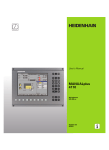
CNC PILOT 4290V7.0—Keyboard
CNC PILOT 4290 V7.0—Keyboard
Manual operating mode
INS (insert)
■ Insert list element
■ Close dialog box, save data
Automatic operating mode
Programming modes (DIN PLUS,
Simulation, TURN PLUS)
Organization modes (Parameter,
Service, Transfer)
Numerals (0...9)
For entering numbers and selecting soft keys
...
Minus
For entering an algebraic sign
Decimal point
Display error status
Call info system
ESC (escape)
■ Go back by one menu level
■ Close dialog box, do not save data
“Continue key”
For special functions (e.g. marking)
DEL (delete)
■ Deletes the list element
■ Deletes the selected character or the character
to the left of the cursor
ALT (alter)
■ Edit the list element
Enter
To confirm your input
Cursor keys
Moves the cursor by one position
in the direction of the arrow (one
character, one field, one line, etc.)
Page Up, Page Down
■ Go to previous/next screen page
■ Go to previous/next dialog box
■ Switch between input windows
...
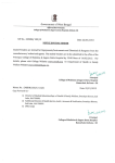
CNC PILOT 4290V6.4—Keyboard
CNC PILOT 4290V6.4—Keyboard
Operating modes key
Call the selection of operating modes
Numerals (0...9)
For entering numbers and selecting soft keys
Display error status
Minus
For entering an algebraic sign
Call the info system
Decimal point
ESC
■ Go back by one menu level
■ Close dialog box, do not save data
Enter
To confirm your input
>> (“continue” key)
For special functions (e.g. marking)
DEL
Delete key
ALT (alter)
■ Edit the list element
INS (insert)
■ Insert list element
■ Close dialog box, save data
...
Cursor keys
Moves the cursor by one position
in the direction of the arrow (one
character, one field, one line, etc.)
Page Up, Page Down
■ Go to previous/next screen page
■ Go to previous/next dialog box
■ Switch between input windows
...
4
The Pilot
Contents
... is your concise programming guide for the HEIDENHAIN
CNC PILOT 4290 contouring control. For more comprehensive information on programming and operating, refer to the
CNC PILOT User's Manual.
DIN Programming ..............................................................
Overview: G Functions for Contour Description ................
6
6
Program Section Codes .....................................................
8
Certain symbols are used in the Pilot to denote specific types
of information:
G Functions for Contour Description ................................. 10
Front, Rear and Lateral Surface Contours .......................... 26
Important note!
Warning: Danger for the user or the machine!
Chapter in User's Manual. Here you will find more
detailed information on the current topic.
The information in this Pilot applies to the CNC PILOT with
the software number 340 340 460-xx (release 6.4) and the
CNC PILOT with the software number 368 650-xx (release
7.0).
Overview: G Functions for the Machining Part ..................
Simple Linear and Circular Movements .............................
Feed Rate, Spindle Speed ..................................................
Tool-Tip and Cutter Radius Compensation (TRK) ................
Datum Shifts, Oversizes ...................................................
Tools, Compensation .........................................................
Turning, Drilling and Threading Cycles ...............................
C-Axis Machining ..............................................................
Other G Functions .............................................................
Subprograms .....................................................................
42
45
48
50
51
57
59
82
90
94
5
DIN Programming
DIN Programming
Program section codes
Page
NC blocks start with the letter “N” followed by a block
number (with up to four digits).
Program section codes
8
Comments are enclosed in parentheses „[...]“. They are
located either at the end of an NC block or in a separate NC
block.
G20-Geo
G21-Geo
Instructions for operation
During editing, the CNC PILOT shows programmed contours
in a maximum of two simulation windows. You can select
the windows from the DIN PLUS main menu (Menu item
”Graphics—Windows”).
■ The starting point of the contour will be marked with a
”small box”
■ If the cursor is located on a block from ”blank or finished
part”, the corresponding contour element will be indicated in
red in the simulation window (”Contour display”)
• Additions/changes to the contour will only be
considered if the ”Graphics” menu item is
reactivated.
• Unambiguous NC block numbers are a prerequisite
for the contour display!
• For programming variables, see ”CNC PILOT 4290
User's Manual”
• For programming in the Y axis, see
”CNC PILOT 4290 with Y Axis User's Manual”
6
Definition of blank
Chuck part, cylinder/tube
Cast part
Basic elements for contour description
G0-Geo
G1-Geo
G2-Geo
G3-Geo
G12-Geo
G13-Geo
Starting point of contour
Line segment
Arc with incr. center dimensioning
Arc with incr. center dimensioning
Arc with abs. center dimensioning
Arc with abs. center dimensioning
Contour form elements
G22-Geo
G23-Geo
G24-Geo
G25-Geo
G34-Geo
G37-Geo
G49-Geo
Recess (standard)
Recess/relief turn
Thread with undercut
Undercut contour
Thread (standard)
Thread (general)
Bore hole at turning center
Page
10
10
Page
11
11
12
12
12
12
Page
13
14
15
16
19
20
22
Overview:
G7-Geo
G8-Geo
G9-Geo
G10-Geo
G38-Geo
G39-Geo
G52-Geo
G95-Geo
G149-Geo
Help commands for contour definition
Precision stop ON
Cycle stop OFF
Precision stop blockwise
Peak-to-valley height
Feed rate reduction
Attributes of superimposed elements
Blockwise oversize
Feed per revolution
Additive compensation
Superimposed contours
G308-Geo
G309-Geo
Beginning of pocket/island
End of pocket/island
Elements of the end face contour
G100-Geo
G101-Geo
G102-Geo
G103-Geo
G300-Geo
G301-Geo
G302-Geo
G303-Geo
G304-Geo
G305-Geo
G307-Geo
G401-Geo
G402-Geo
Starting point of face contour
Line segment on face
Circular arc on face
Circular arc on face
Bore hole on face
Linear slot on face
Circular slot on face
Circular slot on face
Full circle on face
Rectangle on face
Eccentric polygon on face
Linear pattern on face
Circular pattern on face
Page
23
23
23
23
23
24
24
25
25
25
Page
26
26
Elements of the lateral surface contour
G110-Geo
G111-Geo
G112-Geo
G113-Geo
G310-Geo
G311-Geo
G312-Geo
G313-Geo
G314-Geo
G315-Geo
G317-Geo
G411-Geo
G412-Geo
Starting point of lateral surface contour
Line segment on lateral surface
Circular arc on lateral surface
Circular arc on lateral surface
Bore hole on lateral surface
Linear slot, lateral surface
Circular slot on lateral surface
Circular slot on lateral surface
Full circle on cylindrical surface
Rectangle on lateral surface
Eccentric polygon on lateral surface
Linear pattern, lateral surface
Circular pattern, lateral surface
Page
34
34
35
35
36
37
37
37
38
38
39
40
41
Overviesw: Contour description
Help commands for contour description
Page
27
27
28
28
29
30
30
30
31
31
32
32
33
Circular arc on lateral surface
7
Program section codes
Program section codes
When you create a new DIN program, certain program section codes are already entered. Delete or
add codes, depending on the task. A DIN program
must include the codes ”MACHINING” and ”END.”
Overview of program section codes
PROGRAMMKOPF [ PROGRAM HEAD ]
TURRET
CLAMPING DEVICE
ROHTEIL [ BLANK ]
FERTIGTEIL [ FINISHED PART ]
FRONT END
REAR END
CYLINDER SURFACE
AUXILIARY CONTOUR
BEARBEITUNG [ MACHINING ]
ENDE [ END ]
SUBPROGRAM
RETURN
■ SLIDE: NC program is only executed for the indicated slide – No in-
put: NC program is executed for every slide (input: “$1, $2, ...”)
■ UNIT: unit of measurement ”metric/inches”—No input: the unit set
in control parameter 1 is used
The ”Unit” can be programmed only when a new program is
being created (set under PROGRAM HEAD). It is not possible
to post-edit this entry.
TURRET x
contains the assignment for the tool carrier x (x: 1..6). If the tool is described in the data bank, enter the T number and the ID number. Alternately, you can define the tool parameters in the NC program.
Tool data input:
Call the tool input: INS key
T-number: position in the tool carrier
ID (identification number): reference to the tool database– No input: tool data is not included in the tool database.
Simple tool:
■ Only suitable for simple traverse paths and turning cycles (G0...G3,
G12, G13; G81...G88).
PROGRAMMKOPF [ PROGRAM HEAD ]
The PROGRAM HEAD comprises:
■ Organizational information (does not influence
program execution)
■ Setup information (does not influence program
execution)
8
■ There is no regeneration of the contour.
■ Cutter radius compensation is carried out.
■ Data are not stored in the tool database (”Simple tools” have no ID).
Continued
Enhanced input: No limitations for use of the tool (data is transferred
to the tool database during program conversion.)
■ LATERAL SURFACE X.. : section ”Lateral surface
contour” – ”X..”
■ AUXILIARY CONTOUR: indicates further contour
CLAMPING DEVICE x
Defines the type of clamping device X used on the spindle (x: 1..4).
If you do not program CLAMPING DEVICE, the machining simulation
assumes there is no clamping device (see also G65).
Parameters
H:
Clamping device number (reference for G65) – Range: 1 H 9
ID:
Identification number of clamping device
X:
Clamping diameter
Q:
Chucking shape – defines the position of the clamping device reference point (see G65)
ROHTEIL [ BLANK ]
Program section for the definition of the blank.
FERTIGTEIL [ FINISHED PART ]
Program section for the contour definition of the finished part.
Additional program section codes within the finished part definition:
■ FRONT END Z.. : Section ”Front end contour” – ”Z..” defines the position of the front contour.
■ REAR SIDE Z.. : Section ”Rear side contour” – ”Z..” defines the position of the rear side contour.
definitions
If you have several independent contour definitions, then repeated use of the program
section codes (FRONT END, REAR END,
etc.) is permitted.
BEARBEITUNG [ MACHINING ]
Program section for the machining of the workpiece.
MACHINING must be included in your program.
ENDE [ END ]
Ends your NC program. The code END must be
included in your program (replaces M30).
Program section codes
If you do not program TURRET, the tools entered in the turret
table will be used.
SUBPROGRAM ”12345678”
If you define a subprogram within your NC program
(within the same file), it is identified with
SUBPROGRAM, followed by the name of the
subprogram (max. 8 characters).
RETURN
Ends your NC subprogram.
9
Blank material for cylinder/pipe G20-Geo
Definition of blank
G20 defines the contour of a cylinder/hollow cylinder.
Parameters
■ Diameter of cylinder/hollow cylinder
X:
■ Diameter of circumference of polygonal blank
Z:
Length of blank
K:
Right edge (distance between workpiece datum and right edge)
I:
Inside diameter for hollow cylinders
Cast part G21-Geo
G21 generates the contour of the blank part from the contour of the
finished part – plus the ”equidistant allowance P.”
Parameters
P:
Equidistant finishing allowance (reference: finished part contour)
Q:
Bore holes yes/no – default: Q=0
■ Q=0: without bore holes
■ Q=1: with bore holes
10
Starting point of turning contour G0 Geo
G0 defines the starting point of a turning contour.
Basic elements for
contour description
Parameters
X, Z: Starting point of the contour (X diameter value)
Line segment in a contour G1-Geo
G1 defines a line segment in a turning contour.
Parameters
X, Z: End point (X diameter value)
A:
Angle to rotary axis – for angle direction see illustration
Q:
Select point of intersection – default: 0
■ Q=0: Near intersection
■ Q=1: Far intersection
B:
Chamfer/rounding
■ B is undefined: Tangential transition
■ B=0: Nontangential transition
■ B>0: Rounding radius
■ B<0: Chamfer width
E:
Special feed-rate factor (0 < E 1) – default: 1
(special feed rate = active feed rate * E)
11
Circular arc in a contour
Basic elements for
contour description
G2/G3-Geo – incremental, G12/G13-Geo – absolute center
coordinates
G2/G3 or G12/G13 defined a circular arc in a contour. The direction of
rotation is visible in the help graphic.
Parameters
X, Z: End point (X diameter value)
R:
Radius
Q:
Selection of intersection – default: 0
■ Q=0: Far intersection
■ Q=1: Near intersection
B:
Chamfer/ rounding at end of circular arc
■ B no entry: tangential transition
■ B=0: no tangential transition
■ B>0: Radius of rounding
■ B<0: Width of chamfer
E:
Special feed-rate factor (0 < E 1) – default: 1
(special feed rate = active feed rate * E)
Example: G2-Geo
With G2/G3:
I:
Center point incremental (distance from starting point to center
as radius)
K:
Center point incremental (distance from starting point to center)
With G12/G13:
I:
Absolute center (radius)
K:
Absolute center
12
Example: G12-Geo
Recess (standard) G22-Geo
Parameters
X:
Starting point of recess on the end surface (diameter)
Z:
Starting point of recess on lateral surface
I, K: Inside corner
■ I for recess on front face: recess end point (diameter value)
■ K for recess on end face: recess base
■ I for recess on lateral surface: recess base (diameter value)
■ K for recess on lateral surface: recess end point
Ii, Ki: Inside corner – incremental (pay attention to sign !)
■ Ii for recess on end face: recess width
■ Ki for recess on end face: recess depth
■ Ii for recess on lateral surface: recess depth
■ Ki for recess on lateral surface: end point of recess (recess
width)
B:
Outside radius/chamfer (at both ends of the recess) – default: 0
■ B>0: Radius of the rounding
■ B<0: Width of the chamfer
R:
Inside radius (in both corners of recess) – default: 0
Form elements
for contour description
G22 defines a recess on an axis-parallel reference element (G1). G22 is
assigned to the previously programmed reference element.
Program either X or Z.
13
Form elements
for contour description
Recess (general) G23-Geo
G23 defines a recess on a linear reference element (G1). G23 is
assigned to the previously programmed reference element. On the lateral surface the recess can be positioned on an inclined reference
straight.
Parameters
H:
Recess type – default: 0
■ H=0: symmetrical recess
■ H=1: free rotation
X:
Center point of recess on end surface (diameter)
Z:
Center point of recess on lateral surface
I:
Recess depth and position
■ I>0: recess to right of reference element
■ I<0: recess to left of reference element
K:
Recess width (without chamfer/rounding)
U:
Recess diameter (diameter of recess floor) – use only if the
reference element runs parallel to the Z axis.
A:
Recess angle – default: 0
■ with H=0: 0° A < 180° (angle between edges of recess)
■ with H=1: 0° < A 90° (angle between reference straight and
recess edge)
B:
Outside radius/corner. Starting point near corner - default: 0
■ B>0: Radius of rounding
■ B<0: Width of chamfer
P:
Outside radius/corner. Starting point distant from corner - default: 0
■ P>0: Radius of rounding
■ P<0: Width of chamfer
R:
Inside radius (in both corners of recess) – default: 0
Simple recess
The CNC PILOT refers the recess depth to the reference
element. The recess base runs parallel to the reference
element.
14
Recess or free rotation
Thread with undercut G24-Geo
Calling the contour macro:
N..G1 X..Z..B..
/Starting point for thread
N..G24 F..I..K..Z.. /Contours for thread and undercut
N..G1 X..
/Next surface element
Parameters
F:
Thread pitch
I:
Depth of undercut (radius)
K:
Width of undercut
Z:
End point of the undercut
Form elements
for contour description
G24 defines a linear base element, a linear thread (external or internal
thread; metric ISO fine-pitch thread DIN 13 Part 2, Series 1) and a subsequent thread undercut (DIN 76).
• G24 can be used only if the thread is cut in the direction of
contour definition.
• The thread is machined with G31.
15
H:
Undercut contour G25-Geo
Form elements
for contour description
G25 generates the following undercut contours in paraxial contour
corners. The meaning of the parameters depends on the type of
undercut.
If you program G25
■ after the reference element, the undercut is turned at the end of the
reference element.
■ before the reference element, the undercut is turned at the
beginning of the reference element.
Type of undercut – default: 0
■ H=4: undercut form U
■ H=0, 5: undercut form DIN 509 E
■ H=6: undercut form DIN 509 F
■ H=7: thread undercut DIN 76
■ H=8: undercut form H
■ H=9: undercut form K
Calling the contour macro (example):
N..G1 Z..
/Linear element as reference
N..G25 H..I..K.. .. /Undercut contour
N..G1 X..
/Next surface element
Parameters
Undercut form U (H=4)
Parameters
I:
Depth of undercut (radius)
K:
Width of undercut
R:
Inside radius (in both corners of recess) – default: 0
P:
Outside radius/chamfer – default: 0
■ P>0: radius of the rounding
■ P<0: width of the chamfer
Continued
16
Undercut form U (H=4)
Parameters
I:
Depth of undercut (radius)
K:
Width of undercut
R:
Undercut radius (in both corners of the undercut)
W:
Undercut angle
If you do not enter any parameters the CNC PILOT calculates
the values from the diameter (see User's Manual, section
“Undercut Parameters DIN 509 E”).
Undercut DIN 509 E (H=0, 5)
Undercut DIN 509 F (H=6)
Form elements
for contour description
Undercut DIN 509 E (H=0, 5)
Parameters
I:
Depth of undercut (radius)
K:
Width of undercut
R:
Undercut radius (in both corners of the undercut)
P:
Transverse depth
W:
Undercut angle
A:
Transverse angle
If you do not enter any parameters the CNC PILOT calculates
the values from the diameter (see User's Manual, section
“Undercut Parameters DIN 509 F”).
Continued
Undercut DIN 509 F (H=6)
17
Form elements
for contour description
Undercut DIN 76 (H=7)
Parameters
I:
Depth of undercut (radius)
K:
Width of undercut
R:
Undercut radius (in both corners of the undercut) – default:
R=0.6*I
W:
Undercut angle – default: 30°
Undercut DIN 76 (H=7)
Undercut form H (H=8)
If you do not enter W, it will be calculated on the basis of K and R. The
final point of the undercut is then located at the ”final point contour.”
Parameters
K:
Width of undercut
R:
Undercut radius – no value: the circular element is not machined
W:
Plunge angle – no value: W is calculated
Continued
18
Undercut form H (H=8)
Parameters
I:
Undercut depth
R:
Undercut radius – no value: the circular element is not machined
W:
Undercut angle
A:
Angle to linear axis – default: 45°
Undercut form K (H=9)
Form elements
for contour description
Undercut form K (H=9)
Thread (standard) G34-Geo
G34 defines a simple or an interlinked external or internal thread (metric
ISO fine-pitch thread DIN 13 Series 1). Threads are interlinked by
programming several G01/G34 blocks after each other.
Parameters
F:
Thread pitch – no value: pitch from the standard table
• You need to program a linear contour element as a reference
before G34 or in the NC block containing G34.
• The thread is cut with G31.
19
Thread (general) G37-Geo
Form elements
for contour description
G37 defines the different types of thread. Threads are interlinked by
programming several G01/G34 blocks after each other.
20
Parameters
Q:
Type of thread – default: 1
■ Q=1: metric ISO fine-pitch thread (DIN 13 Part 2, Series 1)
■ Q=2: metric ISO thread (DIN 13 Part 1, Series 1)
■ Q=3: metric ISO taper thread (DIN 158)
■ Q=4: metric ISO tapered fine-pitch (DIN 158)
■ Q=5: metric ISO trapezoid thread (DIN 103 Part 2, Series 1)
■ Q=6: flat metric trapezoid thread (DIN 308 Part 2, Series 1)
■ Q=7: metric buttress thread (DIN 13 Part 2, Series 1)
■ Q=8: cylindrical round thread (DIN 405 Part 1, Series 1)
■ Q=9: cylindrical Whitworth thread (DIN 259)
■ Q=10: tapered Whitworth thread (DIN 2999)
■ Q=11: Whitworth pipe thread (DIN 2999)
■ Q=12: nonstandard thread
■ Q=13: UNC US coarse thread
■ Q=14: UNF US fine-pitch thread
■ Q=15: UNEF US extra-fine-pitch thread
■ Q=16: NPT US taper pipe thread
■ Q=17: NPTF US taper dryseal pipe thread
■ Q=18: NPSC US cylindrical pipe thread with lubricant
■ Q=19: NPFS US cylindrical pipe thread without lubricant
F:
Thread pitch – must be entered for Q=1, 3..7, 12.
P:
Thread depth – enter only for Q=12.
K:
Runout length (for threads without undercut) –
default: 0
Continued
• Program a linear contour element as a
reference before G37.
• The thread is cut with G31.
• For standard threads, the parameters P, R,
A and W are defined by the CNC PILOT.
• Use Q=12 if you wish to use individual
parameters.
The thread is generated to the length of the
reference element. For the machining of
threads without an undercut, it is necessary
to program an additional linear element so
that the overrun can be executed by the CNC
PILOT without danger of collision.
H:
A:
W:
R:
E:
Reference point (position of thread runout) – default: 0
■ D=0: runout at end of reference element
■ D=1: runout at beginning of reference element
Number of grooves – default: 1
Edge angle left – enter only for Q=12.
Edge angle right – enter only for Q=12.
Thread width – enter only for Q=12.
Variable pitch (increases/reduces the pitch per revolution by E) –
default: 0
Form elements
for contour description
D:
21
Bore hole (centered) G49-Geo
Form elements
for contour description
G49 defines a single bore hole with countersink and thread at the
turning center (front or end face).
Parameters
Z:
Starting position for hole (reference point)
B:
Bore hole diameter
P:
Depth of hole (excluding point)
W:
Point angle – default: 180°
R:
Countersinking diameter
U:
Countersinking depth
E:
Countersinking angle
I:
Thread diameter
J:
Thread depth
K:
Thread runout length
F:
Thread pitch
V:
Left-hand or right-hand thread - default: 0
■ V=0: Right-hand thread
■ V=1: Left-hand thread
A:
Angle (position of bore hole) – default: 0
■ A=0: front end
■ A=180: tail end
O:
Centering diameter
• G49 is programmed in the FINISHED PART section (not in
the FRONT or REAR SIDE section).
• The contour defined with G49 is machined with G71...G74.
22
Accurate stop ON
Accurate stop OFF
Accurate stop blockwise
influences finishing feed rate for total contour
influences finishing feed rate for basic contour elements block
by block
G39 Only for form elements:
■ influences finishing feed rate
■ additive compensation values
■ equidistant finishing allowances
G52 Equidistant finishing allowances – blockwise
G95 defines finishing feed rate for total contour
G149 additive compensation values for total contour
Accurate stop ON G7-Geo
G7 switches the ”precision stop” on modally. In a ”precision stop,” the
CNC PILOT does not start the next block until the ”tolerance window”
around the end point is reached (for tolerance window, see machine
parameters 1106, 1156, ...).
• The NC block containing G7 is also executed with a precision
stop.
• ”Precision stop” is used for basic contour elements that are
executed with G890 or G840.
Precision stop OFF G8-Geo
G8 switches the precision stop off. The block containing G8 is executed
without a precision stop.
Blockwise accurate stop G9-Geo
G9 activates a precision stop for the NC block in
which it is programmed (see also ”G7 Geo”).
Peak-to-valley height (surface texture)
G10-Geo
G10 influences the finishing feed rate of G890 and
thus determines the surface roughness of the
workpiece.
Basics of programming
■ The peak-to-valley height activated with G10 is modal.
■ G10 without parameters deactivates peak-to-valley
height.
■ G95 Geo deactivates peak-to-valley height.
■ G10 RH... (without ”H”) overwrites the valid peakto-valley roughness block by block.
■ G38 Geo overwrites the valid peak-to-valley
roughness block by block.
Help commands for
contour description
Overview: Help commands for contour description
G7
G8
G9
G10
G38
Parameters
H:
Type of surface texture (see also DIN 4768)
■ H=1: general roughness (profile depth) Rt1
■ H=2: average roughness Ra
■ H=3: mean roughness Rz
RH: Peak-to-valley roughness (in µm, inches: µinch)
The peak-to-valley height applies only for
basic contour elements.
23
Feed rate reduction factor G38-Geo
Help commands
for contour description
G38 defines a special feed rate for G890.
24
Parameters
E:
Special feed-rate factor (0 < E 1) – default: 1
(special feed rate = active feed rate * E)
Basics of programming
■ G38 is a non-modal function.
■ G38 is programmed before the contouring
element for which it is destined.
■ G38 replaces another special feed rate or a
programmed peak-to-valley height.
The ”special feed rate” applies only for basic
contour elements.
Attributes for superimposed elements G39-Geo
G39 influences the machining of G890 for the superimposed
elements (form elements):
✲■ Chamfers/rounding arcs (for connecting base elements)
■ Undercuts
■ Recesses
Influence on machining:
■ Special feed rate
■ Peak-to-valley height
■ Additive D compensation
■ Equidistant oversizes
Parameters
F:
Feed per revolution
V:
Type of surface texture (see also DIN 4768)
■ V=1: general roughness (profile depth) Rt1
■ V=2: average roughness Ra
■ V=3: mean roughness Rz
RH: Peak-to-valley height (µm, inch mode: µinch)
D:
Number of the additive compensation (901 D 916)
P:
H:
E:
Finishing allowance (radius)
(Translation of P) absolute / additive – default: 0
■ H=0: P replaces G57/G58 allowances
■ H=1: P is added to G57/G58 allowances
Special feed-rate factor (0 < E 1) – default: 1
(special feed rate = active feed rate * E)
Basics of programming
■ G39 is a non-modal function.
■ G39 is programmed before the contour element
for which it is destined.
■ G50 before a cycle (MACHINING section) switches
G39 oversizes for this cycle off.
Only use peak-to-valley height (”V, RH”),
finishing allowance (”F”) and special feed
rate (”E”) alternately!
Additive compensation G149-Geo
G52 defines an equidistant finishing allowance which is taken into
consideration in G810, G820, G830, G860 and G890.
The CNC PILOT manages 16 tool-independent
correction values.
Basics of programming
■ G52 is a non-modal function.
■ G52 is programmed in the NC block containing the contour element
for which it is destined.
■ G50 before a cycle (MACHINING section) switches G52 oversizes for
this cycle off.
To activate the additive correction function, program
G149 followed by a „D number“ (for example, G149
D901). ”G149 D900” resets the additive
compensation function.
Parameters
P:
Finishing allowance (radius)
H:
(Translation of P) absolute / additive – default: 0
■ H=0: P replaces G57/G58 allowances
■ H=1: P is added to G57/G58 allowances
Basics of programming
■ Additive compensation is effective from the block
in which G149 is programmed.
■ An additive compensation remains active until:
• the next ”G149 D900”
• the end of the finished part description
Parameters
D:
Additive compensation - Default: D900
Range: 900 to 916
Help commands for
contour description
Blockwise finishing allowance G52-Geo
Feed rate per revolution G95-Geo
G95 influences the finishing feed rate of G890.
Note the direction of contour description!
Basics of programming
■ G95 is a modal function
■ G10 switches the G95 finishing feed rate off.
Parameters
F:
Feed per revolution
• Use peak-to-valley height and finishing feed rate alternatively.
• The G95 finishing feed rate replaces a finishing feed rate
defined in the machining program.
25
Start of pocket/island G308-Geo
G308 defines a new reference level/reference diameter for
hierarchically nested front face or lateral surface contours.
Overlapped contours
Parameters
P:
Depth for pocket, height for islands
The algebraic sign of ”Depth P” defines the position of the milling
contour:
■ P<0: Pocket
■ P>0: Island
Section
P
Surface
Milling floor
FRONT END
FRONT END
REAR END
REAR END
CYLINDER SURFACE
CYLINDER SURFACE
P<0
P>0
P<0
P>0
P<0
P>0
Z
Z+P
Z
Z–P
X
X+(P*2)
Z+P
Z
Z–P
Z
X+(P*2)
X
The milling cycles machine from the ”surface” toward the ”milling
floor.”
X:
Z:
P:
Reference diameter from the section code
Reference plane from the section code
”Depth” from G308 or from the cycle parameters
End pocket/island G309-Geo
G309 ends a reference level. Every reference plane defined with G308
must be ended with G309!
26
• Note with ”P”: the addition of a negative
number reduces the result, and the
subtraction of a negative number increases
the result.
• Island: The area-milling cycles machine
the complete area specified in the contour
definition. Islands that are defined within
this area are not considered.
Starting point of end face contour G100-Geo
Parameters
X, C: Starting point in polar coordinates (diameter, starting angle)
XK,YK: Starting point in Cartesian coordinates
Base elements for
front/end face contour
G100 defines the starting point of an end face contour.
Linear segment in end face contour G101-Geo
G101 defines a line segment in an end face contour.
Parameters
X, C: End point in polar coordinates (diameter, end angle)
XK,YK: End point in Cartesian coordinates
A:
Angle to positive XK-axis
B:
Chamfer/rounding
■ B is undefined: Tangential transition
■ B=0: Nontangential transition
■ B>0: Rounding radius
■ B<0: Chamfer width
Q:
Select point of intersection – default: 0
■ Q=0: Near intersection
■ Q=1: Far intersection
27
Circular arc in front end contour G102-/G103-Geo
Base elements for
front/end face contour
G102/G103 defines a circular arc in a front/end face contour. The
direction of rotation is visible in the help graphic.
Parameters
X, C: End point in polar coordinates (diameter, end angle)
XK,YK: End point in Cartesian coordinates
R:
Radius
I, J: Center in Cartesian coordinates
Q:
Selection of intersection – default: 0
■ Q=0: Far intersection
■ Q=1: Near intersection
B:
Chamfer/ rounding at end of circular arc
■ B no entry: tangential transition
■ B=0: no tangential transition
■ B>0: Radius of rounding
■ B<0: Width of chamfer
G102-Geo
The end point may not be the same as the starting point (not a
full circle).
28
G103-Geo
G300 defines a bore hole with countersink and thread on the front/end
face.
Parameters
XK,YK: Center of hole
B:
Hole diameter
P:
Depth of hole (excluding point)
W:
Point angle – default: 180°
R:
Countersinking diameter
U:
Countersinking depth
E:
Countersinking angle
I:
Thread diameter
J:
Thread depth
K:
Thread runout length
F:
Thread pitch
V:
Left-hand or right-hand thread - default: 0
■ V=0: Right-hand thread
■ V=1: Left-hand thread
A:
Angle (reference: Z-axis)
■ Front end – default: 0° (range: –90° < A < 90°)
■ Rear end – default: 180° (range: 90° < A < 270°)
O:
Centering diameter
Figures on end face contour
Bore hole on end face G300-Geo
Use G71...G74 to machine bore holes defined with G300-Geo.
29
Figures on end face contour
Linear slot on the end face G301-Geo
G301 defines a linear slot on the front/rear end face.
Parameters
XK,YK: Center of slot
A:
Angle of slot length (reference: XK-axis) – default: 0°
K:
Slot length
B:
Slot width
P:
Depth/height – no entry: ”P” from G308
■ P<0: Pocket
■ P>0: Island
Circular slot on the front end G302-/G303-Geo
G302/G303 defines a circular slot on the front/rear end face.
Parameters
I, J: Center of slot curvature
R:
Curvature radius (reference: center point path of the slot)
A:
Angle of slot starting point (reference: XK-axis) – default: 0
W:
Angle of slot end point (reference: XK-axis)
B:
Slot width
P:
Depth/height – no entry: ”P” from G308
■ P<0: Pocket
■ P>0: Island
30
Example: G302-Geo
G304 defines a full circle on the front/rear end face.
Parameters
XK,YK: Circle center
R:
Circle radius
P:
Depth/height – no entry: ”P” from G308
■ P<0: Pocket
■ P>0: Island
Figures on end face contour
Full circle on front end face G304-Geo
Rectangle on end face G305-Geo
G305 defines a rectangle on the front/rear end face.
Parameters
XK,YK: Center of rectangle
A:
Angle to longitudinal axis of rectangle (reference: XK-axis) – default:
0°
K:
Length of rectangle
B:
(Height) width of rectangle
R:
Chamfer/rounding - default: 0
■ R>0: Radius of rounding
■ R<0: Width of chamfer
P:
Depth/height – no entry: ”P” from G308
■ P<0: Pocket
■ P>0: Island
31
Figures on end face contour
Regular polygon on end face G307-Geo
G307 defines a regular polygon on the front/rear end face.
Parameters
XK,YK: Polygon center point
Q:
Number of edges (Q3)
A:
Angle to a polygon side (reference: XK-axis) – default: 0°
K:
Edge length
■ K>0: Edge length
■ K<0: Key width (inside diameter)
R:
Chamfer/rounding - default: 0
■ R>0: Radius of rounding
■ R<0: Width of chamfer
P:
Depth/height – no entry: ”P” from G308
■ P<0: Pocket
■ P>0: Island
Linear pattern on end face G401-Geo
G401 defines a linear pattern on the front/rear end face. G401 is
effective for the bore hole/figure defined in the following block
(G300..305, G307).
Parameters
Q:
Number of figures
XK,YK: Starting point of pattern
I, J: End point of pattern
Ii, Ji: Distance between two figures (in XK, YK direction)
A:
Angle to the longitudinal axis of the pattern (reference: XK-axis)
R:
Total length of pattern
Ri:
Distance between two figures (pattern distance)
32
G402 defines a circular pattern on the front/rear end face. G402 is
effective for the figure defined in the following block (G300..305, G307).
Programming notes
■ Program the hole/figure in the following block without a center –
exception: circular slot.
■ The milling cycle (MACHINING section) calls the hole/figure in the
following block - not the pattern definition.
Parameters
Q:
Number of figures
K:
Pattern diameter
A, W: Starting angle, end angle – position of first/last figure (reference:
XK-axis) – default: A=0°; W=360°
Wi: Angle between two figures
V:
Direction (orientation) – default: 0
■ V=0 – without W: Distribution over complete circle
■ V=0 – with W: Distribution over long arc
■ V=0 – with Wi: Algebraic sign of Wi defines the direction
(Wi<0: Pattern in clockwise direction)
■ V=1 – with W: Pattern in clockwise direction
■ V=1 – with Wi: Pattern in clockwise direction (algebraic sign of
Wi is without meaning)
■ V=2 – with W: Pattern counterclockwise
■ V=2 – with Wi: Pattern counterclockwise (algebraic sign of Wi
has no effect)
XK,YK: Center of pattern
H:
Position of figures – default: 0
■ H=0: Normal position – figures are rotated about the circle
center (rotation)
■ H=1: Original position – position of figure remains the
unchanged with respect to the coordinate system (translation)
Figures on end face contour
Circular pattern on end face G402-Geo
33
Starting point of lateral surface contour G110-Geo
Basic elements of
lateral surface contour
G110 defines the starting point of a lateral surface contour.
Parameters
Z, C: Starting point of contour (starting point, starting angle)
CY: Starting angle as linear dimension
Program either Z, C or Z, CY.
Straight line in a lateral surface contour G111-Geo
G111 defines a line segment in a lateral surface contour.
Parameters
Z, C: End point, end angle
CY: End angle as linear dimension
A:
Angle (reference: negative Z axis)
B:
Chamfer/rounding
■ B is undefined: Tangential transition
■ B=0: Nontangential transition
■ B>0: Rounding radius
■ B<0: Chamfer width
Q:
Select point of intersection – default: 0
■ Q=0: Near intersection
■ Q=1: Far intersection
Program either Z, C or Z, CY.
34
Circular arc in lateral surface contour G112-/G113-Geo
Parameters
Z, C: End point, end angle
CY: End angle as linear dimension
R:
Radius
K:
Center point (in Z direction)
W:
Angle of the center point
J:
Angle of the center point as a linear value
Q:
Selection of intersection – default: 0
■ Q=0: Far intersection
■ Q=1: Near intersection
B:
Chamfer/rounding
■ B is undefined: Tangential transition
■ B=0: Nontangential transition
■ B>0: Rounding radius
■ B<0: Chamfer width
G112-Geo
Basic elements of
lateral surface contour
G112/G113 defines a circular arc in a lateral surface contour. The
direction of rotation is visible in the help graphic.
G113-Geo
35
• Program either Z, C or Z and CY, or K, W or K and J.
• Program either center or radius.
• For radius: only arcs 180° possible
Bore hole on lateral surface G310-Geo
Figures on the
lateral surface
G310 defines a bore hole with countersink and thread on the lateral
surface.
Parameters
Z, C: Center point of bore hole (position, angle)
CY: Angle as linear dimension
B:
Hole diameter
P:
Depth of hole (excluding point)
W:
Point angle – default: 180°
R:
Countersinking diameter
U:
Countersinking depth
E:
Countersinking angle
I:
Thread diameter
J:
Thread depth
K:
Thread runout length
F:
Thread pitch
V:
Left-hand or right-hand thread - default: 0
■ V=0: Right-hand thread
■ V=1: Left-hand thread
A:
Angle (reference: Z axis) – default: 90° = vertical hole (range:
0° < A < 180°)
O:
Centering diameter
Use G71...G74 to machine contours defined with G310.
36
Linear slot on lateral surface G311-Geo
G311 defines a linear slot on the lateral surface.
Figures on the
lateral surface
Parameters
Z, C: Center point of slot (position, angle)
CY: Angle as linear dimension
A:
Angle to longitudinal axis of slot (reference: Z-axis) – default: 0°
K:
Slot length
B:
Slot width
P:
Pocket depth – no entry: ”P” from G308
Circular groove on lateral surface G312-/G313-Geo
G312/G313 defines a circular slot on the lateral surface.
Parameters
Z, C: Center of curvature of slot (position, angle)
CY: Angle as linear dimension
R:
Curvature radius (reference: center point path of the slot)
A:
Angle of slot starting point (reference: Z axis)
W:
Angle of slot end point (reference: Z axis)
B:
Slot width
P:
Pocket depth – no entry: ”P” from G308
Example: G312-Geo
37
Full circle on lateral surface G314-Geo
G314 defines a full circle on the lateral surface.
Figures on the
lateral surface
Parameters
Z, C: Circle center (position, angle)
CY: Angle as linear dimension
R:
Circle radius
P:
Pocket depth – no entry: ”P” from G308
Rectangle on lateral surface G315-Geo
G315 defines a rectangle on the lateral surface.
Parameters
Z, C: Center point of rectangle (position, angle)
CY: Angle as linear dimension
A:
Angle to longitudinal axis of rectangle (reference: Z-axis) – default: 0°
K:
Length of rectangle
B:
Width (height) of the rectangle
R:
Chamfer/rounding - default: 0
■ R>0: Radius of rounding
■ R<0: Width of chamfer
P:
Pocket depth – no entry: ”P” from G308
38
Regular polygon on lateral surface G317-Geo
Parameters
Z, C: Center point of polygon (position, angle)
CY: Angle as linear dimension
Q:
Number of edges (Q3)
A:
Angle to a polygon side (reference: Z-axis) – default: 0°
K:
Edge length
■ K>0: Edge length
■ K<0: Key width (inside diameter)
R:
Chamfer/rounding - default: 0
■ R>0: Radius of rounding
■ R<0: Width of chamfer
P:
Pocket depth – no entry: ”P” from G308
Figures on the
lateral surface
G317 defines a regular polygon on the lateral surface.
39
Linear pattern on lateral surface G411 Geo
Figures on the
lateral surface
G411 defines a linear pattern on the lateral surface. G411 is effective for
the bore hole/figure defined in the following block (G310..315, 317).
40
Parameters
Q:
Number of figures
Z, C: Starting point, starting angle of pattern
K, W: End point, end angle of pattern
Ki:
Distance between the figures (in Z-direction)
Wi: Angular distance between the figures
A:
Angle of pattern length axis (reference: Z axis)
R:
Total length of pattern
Ri:
Distance between two figures (pattern distance)
If you program Q, Z and C, the bore holes/figures will be
ordered in a regular manner along the circumference.
Circular pattern on lateral surface G412 Geo
G412 defines a circular pattern on the lateral surface. G412 is effective
for the bore hole/figure defined in the following block (G310..315, 317).
Parameters
Q:
Number of figures
K:
Diameter of circle
A, W: Starting angle, end angle – position of first/last figure (reference:
Z-axis) – default: A=0°; W=360°
Wi: Distance between two figures
V:
Direction (orientation) – default: 0
■ V=0 – without W: Distribution over complete circle
■ V=0 – with W: Distribution over long arc
■ V=0 – with Wi: Algebraic sign of Wi defines the direction
(Wi<0: Pattern in clockwise direction)
■ V=1 – with W: Pattern in clockwise direction
■ V=1 – with Wi: Pattern in clockwise direction (algebraic sign of
Wi is without meaning)
■ V=2 – with W: Pattern counterclockwise
■ V=2 – with Wi: Pattern counterclockwise (algebraic sign of Wi
has no effect)
Z, C: Position, angle to midpoint of pattern
H:
Position of figures – default: 0
■ H=0: Normal position – figure is rotated about the circle center
(rotation)
■ H=1: Original position – position of figure remains the
unchanged with respect to the coordinate system (translation)
Figures on the
lateral surface
Programming notes
■ Program the hole/figure in the following block without a center –
exception: circular slot.
■ The milling cycle (MACHINING section) calls the hole/figure in the
following block - not the pattern definition.
41
Overview: machining part
G Functions for Machining
The following functions must be preceded with the section
code MACHINING.
For contour-based turning cycles define the reference to the
contour description in ”NS, NE.” You can determine this
reference as follows:
Activate contour display (menu item ”Graphic”).
Place the cursor on the ”NS/NE” field and press the
Continue key.
Select the desired contour element with the left/right arrow
key.
The up/down arrow keys can be used to switch between
several contours (also end face contours, etc.)
Transfer the block number of the contour element (”Enter”
key).
If you activate the up/down arrow keys, the
CNC PILOT also considers contours that are not
displayed on the screen.
Tool positioning without machining
G0
Positioning in rapid traverse
G14 Approach to the tool change position
G701 Rapid traverse to machine coordinates
Page
45
45
46
Simple Linear and Circular Paths
G1
Linear path
G2
Circular path
G3
Circular path
G12 Circular path
G13 Circular path
Page
46
47
47
47
47
Feed rate and spindle speed
Gx26 Speed limit *
G48 Acceleration (slope)
G64 Discontinuous feed rate
Gx93 Feed rate per tooth *
G94 Feed per minute
Gx95 Feed in revolutions
Gx96 Constant surface speed
Gx97 Spindle speed
Page
48
48
49
49
49
49
49
49
Cutter radius compensation (TRC/MCRC)
G40 Switch off TRC/MCRC
G41 TRC/MCRC left
G42 TRC/MCRC right
Page
50
50
50
* ”x” = number of the spindle (0...3)
42
Page
51
51
52
52
52
52
63
54
82
Allowances, safety clearances
G47 Set safety clearances
G50 Switch off allowance
G57 Paraxial allowance
G58 Contour-parallel allowance
G147 Safety clearance (milling)
Page
55
55
56
56
55
Tools, types of compensation
T
Tool change
G148 (Changing the) correction of cut
G149 Additive correction
G150 Compensate right tool tip
G151 Compensate left tool tip
Page
57
57
58
58
58
Simple turning cycles
G80 End of cycle
G81 Simple longitudinal roughing
G82 Simple face roughing
G83 Simple contour-parallel roughing
G85 Undercuts
G86 Simple recessing cycle
G87 Transition radii
G88 Chamfers
Page
59
59
59
60
61
63
64
64
Contour-determined turning cycles
G810 Longitudinal roughing cycle
G820 Face roughing cycle
G830 Contour-parallel roughing cycle
G835 Contour-parallel with neutral tool
G860 Universal recessing cycle
G866 Simple recessing cycle
G869 Recess turning cycle
G890 Finishing cycle
Page
65
65
67
68
69
70
71
72
Thread cycle group
G31 Thread cycle
G32 Single thread cycle
G33 Single thread cut
Page
74
75
76
Drilling cycle group
G36 Tapping
G71 Simple drilling cycle
G72 Boring, sinking, etc.
G73 Tapping cycle
G74
Deep drilling cycle
Page
77
78
79
80
81
C axis
G120 Reference diameter for cylinder
surface machining
G152 Datum shift C-axis
G153 Standardize C-axis
Page
End face machining
G100 Rapid traverse, front/rear face
G101 Linear movement, front/rear face
G102 Circular arc, front/rear face
G103 Circular arc, front/rear face
Page
83
83
84
84
Overview: machining part
Datum shift
Overview Datum shifts
G51 Datum shift (relative)
G53 Parameter-dependent datum shift
G54 Parameter-dependent datum shift
G55 Parameter-dependent datum shift
G56 Additive datum shift (relative)
G59 Datum shift (absolute)
G121 Contour mirroring/shifting
G152 Datum shift C-axis
82
82
82
43
Overview:
G-functions for machining part
44
Cylindrical surface machining
G110 Rapid traverse, cylindrical surface
G111 Linear movement, cylindrical surface
G112 Circular arc, cylindrical surface
G113 Circular arc, cylindrical surface
G120 Reference diameter for cylinder
surface machining
Page
85
85
86
86
Milling Cycles
G840 Contour milling
G845 Pocket milling – roughing
G846 Pocket milling – finishing
Page
87
89
89
Other G Functions
G4
Dwell time
G7
Accurate stop ON
G8
Accurate stop OFF
G9
Block precision stop
G60 Deactivate protection zone
G65 Chucking equipment for graphics
G98 Assignment spindle – workpiece
G121 Contour mirroring/shifting
G702 Regeneration of contour storing/loading
G703 Regeneration of contour ON/OFF
G720 Spindle synchronization
G905 Measuring C-angle offset
G918 Feedfor ward control ON/OFF
G919 Spindle override 100%
G920 Deactivate datum shift
G921 Deactivate datum shift and tool
dimensions
Page
90
90
90
90
90
91
91
54
92
92
92
92
93
93
93
82
93
Other G Functions
G980 Activate datum shift
G981 Activate datum shift and tool
dimensions
Page
93
Subprograms
Subprogram call
Page
94
See User's Manual
G15 Moving a rotary axis
G30 Converting
G62 One-sided synchronization
G63 Synchronous start of slide
G119 Select C axis
G162 Set synchronizing mark
G192 Minute feed rate for rotary axes
G204 Wait for moment
G600 Tool preselection in magazine/chain
G601 Inserting tool from magazine into carrier
G710 Linking tool dimensions
G711 Activate magazine tool
G717 Update nominal values
G718 Servo lag
G900..999 Special G functions
93
Rapid traverse G0
The tool moves at rapid traverse along the shortest path to the ”target
point.”
Tool positioning
without machining
Parameters
X, Z: Diameter, length to target point (X diameter)
Tool change point G14
The slide moves in rapid traverse to the tool change position. In setup
mode, define permanent coordinates for the tool change.
Parameters
Q:
Sequence – default: 0
0:
Diagonal path of traverse
1:
First in X axis, then in Z
2:
First in Z axis, then in X
3:
X axis only
4:
Z direction only
45
Rapid traverse to machine coordinates G701
The slide moves at rapid traverse on the shortest path to the ”target
point.”
Simple linear
and circular paths
Parameters
X, Z: End point (X diameter value)
”X, Z” refer to the machine datum and the slide datum.
Linear path G1
The tool moves at the programmed feed rate on a line to the ”end point.”
46
Parameters
X, Z: Diameter, length to end point (X diameter)
A:
Angle (angular direction: see graphic support window)
Q:
Selection of intersection – default: Q=0
■ Q=0: Near intersection
■ Q=1: Far intersection
B:
Chamfer/rounding
■ B is undefined: Tangential transition
■ B=0: Nontangential transition
■ B>0: Rounding radius
■ B<0: Chamfer width
E:
Special feed-rate factor (0 < E 1) – default: 1
(special feed rate = active feed rate * E)
Circular path
G2, G3 – incremental, G12, G13 – absolute center coordinates
The tool moves in a circular arc at the feed rate to the ”end point.” The
direction of rotation of G2/G3 or G12/G13 is shown in the graphic
support window.
Parameters
X, Z: Diameter, length to end point (X diameter)
R:
Radius (0 < R 200 000 mm)
Q:
Selection of intersection – default: Q=0
■ Q=0: Far intersection
■ Q=1: Near intersection
B:
Chamfer/rounding
■ B is undefined: Tangential transition
■ B=0: Nontangential transition
■ B>0: Rounding radius
■ B<0: Chamfer width
E:
Special feed-rate factor (0 < E 1) – default: 1
(special feed rate = active feed rate * E)
Example: circular path G2
Simple linear
and circular paths
The special feed rate applies to chamfer/rounding.
Example: circular path G12
47
With G2, G3:
I, K: Center point incremental (distance starting point – center point;
I radius)
With G12, G13:
I, K: Absolute center (I radius)
Feed rate and spindle speed
Speed limitation
G26: Spindle; Gx26: Spindle x (x: 1...3)
G26/Gx26 limits the speed of spindle x. The speed limit remains in
effect until program end or until it is replaced by a new G26/Gx26.
Parameters
S:
(Maximum) speed
Acceleration (slope) G48
G48 specifies the approaching acceleration, braking acceleration, and
the maximum feed rate. G48 is a modal function.
Without G48 the following parameter values apply:
■ Acceleration at approach/deceleration at departure: Machine
parameter 1105 ff ”Acceleration/deceleration of linear axis”
■ and the maximum feed rate from: Machine Parameter 1101 ff ”Maximum axis speed”
Parameters
E:
Acceleration at approach – no input: the parameter values take
effect.
F:
Deceleration at departure – no input: the parameter values take
effect
H:
Programmed acceleration On/Off
■ H=0: switch off programmed acceleration after next traverse
■ H=1: switch on programmed acceleration
P:
Maximum feed rate – no input: Parameter value
48
The ”absolute maximal speed” is specified
in machine parameter 805 and following.
If S > parameter value, the parameter value
takes applies.
• If P > parameter value, the parameter
value applies.
• ”E, F and P” refer to the X or Z axis. The
acceleration/feed rate for the slide is not
higher with axis-parallel traverses.
Feed rate per revolution Gx95
G64 interrupts the programmed feed for a short period of time.
G95: Spindle; Gx95: Spindle x (x: 1...3)
G95/Gx95 defines the feed rate as a function of
drive.
■ For switch-on, program G64 with E and F.
■ For switch-off, program G64 without parameters.
Parameters
E:
Duration of pause (range: 0.01 s < E < 99.99 s)
F:
Parameters
F:
Feed rate in mm/revolution or inch/revolution
Duration of feed rate (range: 0.01 s < E < 99.99 s)
Feed rate per tooth spindle x Gx93
Constant cutting speed Gx96
Gx93 (x: spindle 1...3) defines the feed rate drive-dependent,
depending on the number of teeth of the cutter.
G96: spindle; Gx96: spindle x (x: 1...3)
G96/Gx96 defines a constant cutting speed. The
spindle speed is dependent on the X position of the
tool tip or on the tool diameter (with driven tools).
Parameters
F:
Feed rate per tooth (mm/tooth or inch/tooth)
The actual value display shows the feed rate in mm/rev.
Parameters
S:
Cutting velocity (in m/min or ft/min)
Feed rate constant G94 (minute feed)
Speed Gx97
G94 defines the feed rate as a function of drive.
G97: spindle; Gx97: spindle x (x: 1...3)
G97/Gx97 defines a constant spindle speed.
Parameters
S:
Speed (in revolutions per minute)
Parameters
F:
Feed rate per minute (in mm/min or inch/min)
Feed rate and spindle speed
Interrupted (intermittent) feed G64
49
Tooth and cutter radius
compensation (TRC)
Tooth and cutter radius compensation (TRC/MCRC)
G40, G41, G42
G40: Switch off TRC/MCRC
■ The TRC is effective up to the block before G40.
■ In the block with G40, or in the block after G40, only one straight line
segment permitted (G14 is not permitted).
G41/G42: switch on TRC/MCRC
■ In the block with G41/G42 or after the block with G41/G42, one
straight line segment (G0/G1) is to be programmed.
■ The TRC/MCRC is included after the next contour element.
G41: Switch on TRC/MCRC – displacement of the tool radius in the
direction left of the contour.
G42: Switch on TRC/MCRC – displacement of the tool radius in the
direction right of the contour.
Parameters
Q:
Machining plane – default: 0
■ Q=0: TRC on the turning plane (X-Z plane)
■ Q=1: MCRC on the end face (X-C plane)
■ Q=2: MCRC on the cylindrical surface (Z-C plane)
■ Q=3: MCRC on the end face (X-Y plane)
■ Q=4: MCRC on the cylindrical surface (Y-Z plane)
H:
Output (only with MCRC) – default: 0
■ H=0: Intersecting areas which are programmed in directly
successive contour elements are not machined.
■ H=1: The complete contour is machined – even if certain areas
are intersecting.
O:
Feed rate reduction – default: 0
■ O=0: Feed rate reduction active
■ O=1: No feed rate reduction
50
• If the tool radii > contour radii, it can result
in tool path loops during CRC/MCRC.
Recommendation: Use the finishing cycle
G890 / milling cycle G840.
• Never select MCRC during a perpendicular
approach to the plane.
• Note when calling subprograms with
active TRC/MCRC:
Switch the TRC/MCRC off in the main program if it was switched on in the main program. – Switch the TRC/MCRC off in the
subprogram in which it was switched on.
G51
■ Relative shift
■ Programmed shift
■ Reference: set workpiece datum
G53, G54, G55
■ Relative shift
■ Shift from parameters
■ Reference: set workpiece datum
G56
■ Additive shift
■ Programmed shift
■ Reference: current workpiece datum
G59
■ Absolute shift
■ Programmed shift
■ Reference: machine datum
Zero point shift
Overview
Zero point shift G51
G51 displaces the workpiece datum by ”Z” (or ”X”). The shift is
referenced to the workpiece datum defined in setup operation.
Even if you shift the zero point several times with G51, the
displacement is still always referenced to the workpiece zero point
from the setup mode.
The zero point shift applies until the end of the program or until it is
canceled by another zero point shift.
Parameters
X, Z: Displacement (X radius value) – default: 0
51
Parameter-dependent zero point shift G53, G54, G55
G53, G54, G55 displace the workpiece zero point by the value defined
in the setup parameters 3, 4, 5. The shift is referenced to the workpiece
zero point defined in setup operation.
Zero point shift
Even if you shift the zero point several times with G53, G54, G55, the
displacement is still always referenced to the workpiece datum from
the setup mode.
The datum shift applies until the end of the program or until it is
canceled by another datum shift.
A shift in X must be indicated as a radius value.
Additive zero point shift G56
G56 shifts the workpiece zero point by ”Z” (or ”X”). The displacement
is referenced to the currently active workpiece zero point.
If you shift the workpiece zero point several times with G56, the
displacement is always added to the currently active zero point.
Parameters
X, Z: Shift (X radius value) – default: 0
52
Absolute zero point shift G59
G59 sets the workpiece datum to ”X, Z”. The new datum is valid to the
end of the program.
G59 cancels all previous zero point shifts (with G51, G53..G55
or G59).
Zero point shift
Parameters
X, Z: Datum shift (X radius dimension)
53
G121 contour mirror and shift
Datum shift
G121 mirrors and/or shifts the position of roughed and finished part
contours. The contour is mirrored in the X axis and shifted in the Z
direction. The workpiece datum is not affected.
Parameters
H:
Mirroring – default: 0
■ H=0: Contour shift – no mirroring
■ H=1: Contour shift, mirroring, and reversal of the direction of
contour description
Q:
Mirroring the coordinate system (direction of the Z axis) - default: 0
■ Q=0: No mirroring
■ Q=1: Mirroring
Z:
Shift – default: 0
D:
Mirroring XC/XCR (mirroring/shifting the front and rear face
contours) - default: 0
■ D=0: No mirroring/shifting
■ D=1: Mirroring/shifting
• Lateral surface contours are mirrored/shifted like turning
contours.
• Auxiliary contours are not mirrored.
• Please note for Q=1: The coordinate system including the
contour is mirrored – H=1 mirrors only the contour.
54
Switch off allowance with G50
G47 defines the safety clearance for the turning cycles: G810, G820,
G830, G835, G860, G869, G890; drilling cycles G71, G72, G74 and
milling cycles G840...G846. G47 without parameters activates the
parameter values (machining parameters 2, ... – safety clearances).
G50 switches off allowances defined with G52/G39Geo for the following cycle.
Parameters
P:
Safety clearance
G47 replaces safety clearance set in the machining parameters
or that set in G147.
Allowances, safety clearances
Safety clearance G47
Safety clearance (drilling and milling cycles) G147
G147 defines the safety clearance for milling operations with
G840...G846. Parameter ”K” influences the safety clearance for drilling
operations (G71, G72, G74). G147 replaces the safety clearance set in
”;Machining parameter 2, ... – safety clearances.”
Parameters
I:
Safety clearance in milling direction
K:
Safety clearance in approach direction (feed)
G147 replaces safety clearance set in the machining
parameters or that set in G47.
55
Allowances, safety clearances
Axis-parallel allowance G57
G57 defines different allowances in X and Z. G57 is programmed before
the cycle.
After cycle execution, allowances are
■ deleted: G810, G820, G830, G835, G860, G869, G890
■ not deleted: G81, G82, G83
Parameters
X, Z: Allowance (X diameter value)
If the allowances are programmed with G57 and in the cycle
itself, the cycle allowances are used.
Contour-parallel allowance (equidistant) G58
G58 defines a contour-parallel allowance. A negative allowance is
permitted with G890. G58 is programmed before the cycle.
After cycle execution, allowances are
■ deleted: G810, G820, G830, G835, G860, G869, G890
■ not deleted: G81, G82, G83
Parameters
P:
Allowance
If an offset is programmed with G58 and in the cycle, the
offset from the cycle is used.
56
The ”T” is followed by the WAPP number. You can enter the T number
directly or select it from the tool list (switch with the CONTINUE key).
WAPP number:
W: Tool carrier number
A: Number of the location group
PP: Pocket number in the tool carrier
If you are working with multi tools, program
”T PP.S” or ”T WAPP.S” (S = number of the side tooth).
Tools, types of compensation
Tool call T
(Changing the) cutter compensation G148
”O” defines the wear and tear compensation values to be
compensated. DX and DZ become effective after program start and
after a T command.
Parameters
O:
Selection – default: 0
■ O=0: DX, DZ active – DS inactive
■ O=1: DS, DZ active – DX inactive
■ O=2: DX, DS active – DZ inactive
The recessing cycles G860, G866 automatically take the
”correct” wear compensation into account.
57
Tools, types of compensation
Additive compensation G149
The CNC PILOT manages 16 tool-independent compensation values. To
activate the additive compensation function, program G149 followed by
a „D number“ (for example, G149 D901). ”G149 D900” resets the additive compensation function.
Parameters
D:
Additive compensation - default: D900
Range: 900 to 916
Compensate right tool tip G150
Compensate left tool tip G151
G150/G151 defines the workpiece datum for recessing and button
tools.
G150: datum is on right tip
G151: datum is on left tip
G150/G151 is effective from the block in which it is programmed and
remains in effect up to
■ the next tool change
■ end of the program
• The displayed actual values always refer to the tool tip
defined in the tool data.
• Be sure to switch the direction when you work with TRC
58
Basics of programming
■ The compensation becomes effective only after the
tool has actually moved in the compensation
direction by the compensation value. You must
therefore program G149 one block before the block
in which you want the compensation to apply.
■ An additive compensation remains effective until:
■ The next ”G149 D900”
■ The next tool change
■ The end of the program
End of cycle G80
Simple turning cycles
G80 concludes fixed cycles.
Simple longitudinal roughing G81
Simple face roughing G82
G81/G82 machines (roughs) the contour area described by the current
tool position and ”X, Z”. If you wish to machine an oblique cut, you can
define the angle with I and K.
The tool moves to clearance at the end of the cycle:
■ G81: X – last lift-off coordinate; Z – cycle start point
■ G82: X – cycle start point; Z – last lift-off coordinate
Parameters
X/Z: Contour target point (X diameter)
Q:
G-function Infeed – default: 0
■ 0: infeed with G0 (rapid traverse)
■ 1: infeed with G1 (feed rate)
G81:
I:
Maximum infeed distance in the X direction
■ I<0: with machining the contour line
■ I>0: without machining the contour line
K:
Offset in Z direction – default: 0
G82:
I:
Offset in X direction – default: 0
K:
Maximum infeed distance in the Z direction
■ K<0: with machining the contour line
■ K>0: without machining the contour line
Simple longitudinal roughing G81
• Cutter radius compensation: is not
carried out
• Offsets (G57): are calculated and remain
effective after end of cycle.
• Safety clearance after each step: 1 mm.
59
Simple contour repeat cycle G83
Simple turning cycles
G83 carries out the functions programmed in the following blocks (simple traverse or cycles without contour description) more than once.
G80 ends the machining cycle.
If the number of infeeds differs for the X- and Z axes, the tool first
advances in both axes with the programmed values. The infeed is set to
zero if the target value for one direction is reached.
Notes on programming G83
■ Stands alone in the block
■ Must not be programmed with K variables
■ Must not be nested, not even by calling subprograms
Tool position at end of cycle: Cycle starting point.
Parameters
X/Z: Contour target point (X diameter) - no input: transfer the last X/Z
coordinate
I/K: Maximum infeed (I: radius) – default: 0
• Cutter radius compensation: is not carried out – You can
program the TRC separately with G40..G42.
• Offsets: G57-offsets are calculated; G58-offsets only have
effect if you are working with TRC. Allowances remain in
effect after the end of cycle.
• Safety clearance after each step: 1 mm.
60
Danger of collision !
After each pass, the tool returns on a diagonal path before it advances for the next pass.
If required, program an additional rapid traverse path to avoid a collision.
With the function G85, you can machine undercuts according to DIN
509 E, DIN 509 F and DIN 76 (thread undercut). The CNC PILOT
decides the type of undercut using ”K.” For undercut parameters, see
table.
The adjoining cylinder is machined if the tool is positioned at the
cylinder diameter (”X”) ”in front of” the cylinder.
The undercut roundings are executed with the radius 0.6 * I.
Parameters
X, Z: Destination point (X as diameter value)
I:
Depth/wear allowance (radius)
■ DIN 509 E, F: wear allowance – default: 0
■ DIN 76: undercut depth
Undercut DIN 76 (thread undercut)
K:
Undercut width and type
■ K no input: DIN 509 E
■ K=0: DIN 509 F
■ K>0: undercut length for DIN 76
E:
Reduced feed (for machining the undercut) – no input: active
feed rate
Simple turning cycles
Undercut cycle G85
• Cutter radius compensation: is not carried out
• Allowances: are not considered
Continued
Undercut DIN 509 E
61
Simple turning cycles
62
Undercut angle for undercuts according to DIN 509 E and F: 15°
Transverse angle for an undercut according to DIN 509 F: 8°.
where:
I = depth of undercut
K = width of undercut
R = undercut radius
P = depth of end face
Undercut according to DIN 509 E
Diameter
I
K
R
18
0.25
2
0.6
> 18 – 80
0.35
2.5
0.6
> 80
0.45
4
1
Undercut DIN 509 F
Undercut according to DIN 509 F
Diameter
I
K
R
P
18
0.25
2
0.6
0.1
> 18 – 80
0.35
2.5
0.6
0.2
> 80
0.45
4
1
0.3
Recessing G86
G86 machines simple radial and axial recesses with chamfers. From the
tool position the CNC PILOT calculates a radial/axial or an inside/outside
recess.
Simple turning cycles
If you program an allowance, the control always rough-machines the
recess first. In the second step, the recess is then finish-machined.
G86 machines chamfers at the sides of the recess. If you do not wish
to cut the chamfers, you must position the tool at a sufficient distance
from the workpiece. Calculation of the starting position XS (diameter):
XS = XK + 2 * (1,3 – b)
XK: Contour diameter
b: Chamfer width
Tool position at end of cycle:
■ Radial recess:
X – Starting position; Z – last recess position
■ Axial recess:
X – last recess position; Z – start position
Parameters
X, Z: Target point (X diameter)
Radial recess:
I:
Allowance
■ I>0: Allowance (roughing and finishing)
■ I=0: No finishing
K:
Recess width – no input: a single cut is machined (recess width
= tool width)
Axial recess:
I:
Recess width – no input: a single cut is
machined (recess width = tool width)
K:
Allowance
■ K>0: Allowance (roughing and finishing)
■ K=0: No finishing
E
Period of dwell (dwell time for chip breaking) –
default: Duration of on revolution
■ With finishing allowance: Only for finishing
■ Without finishing allowance: for every
recess
• Cutter radius compensation: is not
carried out
• Allowances are not considered.
63
Transition radii G87
Simple turning cycles
G87 machines transition radii at orthogonal, paraxial inside and outside
corners. The direction for the rounding is taken from the ”position/
machining direction” of the tool.
A preceding longitudinal or transverse element is machined if the tool is
located at the X or Z coordinate of the corner before the cycle is executed.
Parameters
X, Z: Corner point (X diameter)
B
Radius
E
Reduced feed rate – no input: active feed rate
• Cutter radius compensation: is carried out
• Allowances are not considered.
Chamfer G88
G88 machines chamfers at orthogonal, paraxial outside corners. The
direction for the chamfer is taken from the ”position/machining
direction” of the tool
A preceding longitudinal or transverse element is machined if the tool is
located at the X or Z coordinate of the corner before the cycle is executed.
Parameters
X, Z: Corner point (X diameter)
B
Chamfer width
E
Reduced feed rate – no input: active feed rate
• Cutter radius compensation: is carried out
• Allowances are not considered.
64
Longitudinal roughing G810 / Face roughing G820
Parameters
NS, NE: Starting block number, end block number (from the contour
description)
P:
Maximum approach - Maximum infeed distance
I, K: Allowances (I diameter value) – default: 0
E:
Approach behavior
■ E=0: descending contours are not machined
■ E>0: approach behavior
■ no input: feed rate reduced depending on approach angle –
maximum reduction: 50%
X/Z: Cutting limit (X diameter value)
H:
Type of contour smoothing – default: 0
■ H=0: smoothing after each cut
■ H=1: lift off at under 45°, smoothing after last cut
■ H=2: lift off at under 45°, no smoothing
A:
Approach angle (reference: Z axis)
■ G810 – default: 0°/180° (parallel to Z axis)
■ G820 – default: 90°/270° (perpendicular to Z axis)
W:
Departing angle (reference: Z axis)
■ G810 – default: 90°/270° (perpendicular to Z axis)
■ G820 – default: 0°/180° (parallel to Z axis)
Q:
Type of retraction after machining – default: 0
n Q=0: return to starting point (G810: first X and then Z direction;
G820: first Z and then X direction)
■ Q=1: position in front of finished contour
■ Q=2: move to clearance height and stop
Contour-determined
turning cycles
G810/G820 cuts (roughs) the contour range defined by ”NS, NE.”
Contour roughing, longitudinal G810
Continued
65
Contour-determined
turning cycles
V:
D:
B:
Machining chamfers/roundings at start/end of contour – default: 0
chamfer/rounding is machined:
■ V=0: at beginning and end
■ V=1: at beginning
■ V=2: at end
■ V=3: no machining at start or end
■ V=4: only single chamfers/roundings are machined – not the
base element (requirement: the contour consists of a contour
element)
Omit element (influences the machining of undercuts, free
rotations: see table) – default: 0
Slide feed for 4-axis machining
■ B=0: Both slides work on the same diameter – at double feed
rate
■ B<>0: Distance from the ”leading” slide (the lead). The slides
work at equal feed rate on different diameters.
■ B<0: The slides with larger number leads
■ B>0: The slide with smaller number leads.
D
=
G22
G23
H0
G23
H1
G25
H4
G25
H5/6
G25
H7..9
0
•
•
•
•
•
•
1
•
•
•
–
–
–
2
•
•
–
•
•
•
3
•
•
–
–
–
–
4
•
•
–
–
•
–
„•“: Hide elements
66
Contour face roughing G820
• Cutter radius is compensated
• Offsets (G57/G58): are effective
• On 4-axis cycles, ensure that the tools are
identical (tool type, cutting edge radius,
cutting edge angle, etc.).
Contour-parallel roughing G830
Parameters
NS, NE: Starting block number, end block number (from the contour
description)
P:
Maximum approach - Maximum infeed distance
I, K: Allowances (I diameter value) – default: 0
X/Z: Cutting limit (X diameter value)
A, W: Approach angle, departure angle (reference: Z axis)
■ Approach angle – default: 0°/180° (parallel to Z axis)
■ Departure angle – default: 90°/270° (perpendicular to Z axis)
Q:
Type of retraction after machining – default: 0
■ Q=0: return to starting point (first X and then Z direction)
■ Q=1: position in front of finished contour
■ Q=2: move to clearance height and stop
V:
Machining chamfers/roundings at start/end of contour – default:
0; chamfer/rounding is machined:
■ V=0: at beginning and end
D
=
G22
G23
H0
G23
H1
G25
H4
G25
H5/6
G25
H7..9
0
•
•
•
•
•
•
1
•
•
•
–
–
–
2
•
•
–
•
•
•
3
•
•
–
–
–
–
4
•
•
–
–
•
–
„•“: Skipping elements
■ V=1:
■ V=2:
■ V=3:
■ V=4:
D:
at beginning
at end
no machining at start or end
only single chamfers/roundings are
machined – not the base element
(requirement: the contour consists of a
contour element)
Omit element (influences the machining of
undercuts, free rotations: see table) – default: 0
Contour-determined
turning cycles
G830 machines (roughs) the contour area defined by ”NS, NE” parallel
to the contour.
• Cutter radius compensation: is carried out
• Offsets (G57/G58): are effective
67
Contour-parallel with neutral tool G835
Contour-determined
turning cycles
G835 machines the contour area defined by ”NS, NE” parallel to the
contour and bidirectionally.
68
Parameters
NS, NE: Starting and end block numbers (reference to contour section)
P:
Maximum approach - Maximum infeed distance
I, K: Allowances (I diameter value) – default: 0
X/Z: Cutting limit (X diameter value)
A, W: Approach angle, departure angle (reference: Z axis)
n Approach angle – default: 0°/180° (parallel to Z axis)
n Departure angle – default: 90°/270° (perpendicular to Z axis)
Q:
Type of retraction after machining – default: 0
n Q=0: return to starting point (first X and then Z direction)
n Q=1: position in front of finished contour
n Q=2: move to clearance height and stop
V:
Machining chamfers/roundings at start/end of contour – default: 0
chamfer/rounding is machined:
n V=0: at beginning and end
D
=
G22
G23
H0
G23
H1
G25
H4
G25
H5/6
G25
H7..9
0
•
•
•
•
•
•
1
•
•
•
–
–
–
2
•
•
–
•
•
•
3
•
•
–
–
–
–
4
•
•
–
–
•
–
„•“: Skipping elements
n V=1: at beginning
n V=2: at end
n V=3: no machining at start or end
n V=4: only single chamfers/roundings are
D:
machined – not the base element
(requirement: the contour must consist of one
element)
Skip the element (influences the machining of
undercuts, free rotations: see table) – default: 0
• Cutter radius compensation: is carried out
• Offsets (G57/G58): are effective
Recessing G860
Parameters
NS, NE: Starting block number, end block number (reference on contour
section or NS = reference on a recess described with G22-/G23Geo)
I, K: Allowances (I diameter value) – default: 0
Q:
Sequence – default: 0
n Q=0: roughing and finishing
n Q=1: roughing only
n Q=2: finishing only
X/Z: Cutting limit (X diameter value)
V:
Machining chamfers/roundings at start/end of contour – default: 0
chamfer/rounding is machined:
n V=0: at beginning and end
n V=1: at beginning
n V=2: at end
n V=3: no machining
E:
Finishing feed rate – no input: active feed rate
H:
Retraction at end of cycle – default: 0
n H=0: return to starting point (axial recess: first Z and then X
direction; radial recess: first X and then Z direction)
n H=1: position in front of the finished contour
n H=2: move to safety clearance and stop
Contour-determined
turning cycles
G860 machines (indents) the contour area defined by ”NS, NE” axially/
radially.
• Cutter radius compensation: is carried out
• Offsets (G57/G58): are effective
69
Recessing cycle G866
G866 makes a recess defined with G22-Geo
Contour-determined
turning cycles
Calculation of the cut segmentation (SBF: see machining parameter 6):
Maximum offset = SBF * cutting edge width
70
Parameters
NS: Block number (reference to G22-Geo)
I:
Allowance (with precutting) – default: 0
■ I=0: recess is machined in one run
■ I>0: precutting is carried out in the first run; and finishing in the
second
E:
Dwell time – no input: corresponds to a spindle revolution
■ With I=0: for each recess
■ With I>0: only during finishing
• Cutter radius compensation: is carried out
• Allowances: are not considered
Recess turning cycle G869
Parameters
NS, NE: Starting block number, end block number (from the contour
description)
P:
Maximum approach - Maximum infeed distance
R:
Turning depth compensation for finishing – default: 0
I, K: Allowances (I diameter value) – default: 0
X/Z: Cutting limit (X diameter value)
A, W: Approach angle, departure angle – default: opposite from the
recessing direction
Q:
Sequence – default: 0
n Q=0: roughing and finishing
n Q=1: roughing only
n Q=2: finishing only
U:
Direction of turning – default: 0
n U=0: Bidirectional turning
n U=1: Unidirectional turning in direction of contour
H:
Retraction at end of cycle – default: 0
n H=0: return to starting point (axial recess: first Z and then X
direction; radial recess: first X and then Z direction)
n H=1: position in front of the finished contour
n H=2: move to safety clearance and stop
V:
Machining chamfers/roundings at start/end of contour – default: 0
chamfer/rounding is machined:
n V=0: At beginning and end
n V=1: At beginning
n V=2: At end
n V=3: No machining
O:
Recessing feed rate – default: active feed rate
Contour-determined
turning cycles
G869 machines the contour described by ”NS, NE” axially and radially
with alternating recessing and roughing movements.
E:
B:
Finishing feed rate – no input: active feed rate
Offset width – default: 0
• Cycle G869 requires type 26* tools.
• Cutter radius compensation: is performed
• Offsets (G57/G58): are effective
71
Contour finishing G890
Contour-determined
turning cycles
G890 finishes the contour area defined by ”NS, NE” parallel to the
contour.
72
Parameters
NS, NE: Starting block number, end block number (from the contour
description)
E:
Approach behavior
n E=0: descending contours are not machined
nÿE>0: approach behavior
n no input: feed rate reduced depending on approach angle –
maximum reduction: 50%
V:
Machining chamfers/roundings at start/end of contour – default:
0; chamfer/rounding is machined:
n V=0: at beginning and end
nÿV=1: at beginning
nÿV=2: at end
nÿV=3: no machining at start or end
nÿV=4: only single chamfers/roundings are machined – not the
base element (requirement: the contour consists of a contour
element)
Q:
Type of approach – default: 0
nÿQ=0: automatic selection – the CNC PILOT checks the
possibilities for approach:
– diagonal approach
– first X direction, then Z
– equidistant around the barrier
– Omission of the first contour element if the start position is
inaccessible
nÿQ=1: First in X direction, then Z
nÿQ=2: First in Z direction, then X
nÿQ=3: No approach – tool is in the proximity of the starting
point of the contour section
nÿQ=4: Residual finishing
H:
X/Z:
D:
Type of retraction – default: 3
tool lifts off under 45° in the opposite direction
to machining and moves as follows to the
position ”I, K”:
nÿH=0: diagonal
nÿH=1: first X, then Z direction
nÿH=2: first Z, then X direction
nÿH=3: remains at safety clearance
nÿH=4: no retraction movement – tool remains
at the end coordinate
Cutting limit (X diameter value) - no input: no
limit
Omit element (influences the machining of
undercuts, free rotations and recesses: see
table) – default: 1
Continued
O:
End point which is approached at the end of
the cycle – except for H=3 or 4 (I diameter
value)
Feed rate reduction – default: 0
nÿO=0: No feed rate reduction
nÿO=1: Feed rate reduction active
During residual finishing (G890 – Q4), the
CNC PILOT, checks whether the tool can
access the contour recess without collision.
The tool parameter ”width dn” is the basis
of this collision check.
D G22
Form
0
–
G23
(H0)
–
G23
(H1)
–
G25
U
–
G25
E, F
–
G25
G, H
–
G25
K
–
1
–
–
•
–
•
•
•
2
–
–
•
–
–
–
–
3
–
–
–
–
•
•
•
4
–
–
•
–
–
•
•
5
–
–
•
–
•
•
–
6
–
–
•
–
•
–
–
7
•
•
•
•
•
•
•
„•“: Skipping elements
Contour-determined
turning cycles
I, K:
Other D codes for skipping undercuts/recesses:
G-call
Function
G22
G22
G23 H0
G23 H1
G23 H4
G23 H5
G23 H6
G23 H7
G23 H8
G23 H9
Gasket recess
Retaining ring recess
General recess
Free rotation
Undercut form U
Undercut form E
Undercut form F
Undercut form G
Undercut form H
Undercut form K
D code
512
1.024
256
2.048
32.768
65.536
131.072
262.144
524.288
1.048.576
73
Thread cycle G31
Thread cycle group
G31 machines threads defined with G24-Geo, G34-Geo or G37-Geo.
G31 also machines successions of threads and multiple threads.
74
Chamfer length, overrun length: If you do not program ”B, P”,the
CNC PILOT will automatically determine the lengths from adjacent
undercuts or axis-parallel recesses. If no undercut/recess exists, the
chamfer and overrun lengths from Machining Parameter 7 will be used.
Parameters
NS: Block number (from the finished part description containing the
basic block G1-Geo for thread contour definition)
I:
Maximum approach - Maximum infeed distance
B, P: Chamfer length, overrun length
D:
Cutting direction (reference: defined direction for basic element)
– default: 0;
■ D=0: same direction
■ D=1: opposite direction
V:
Type of feed – default: 0;
■ V=0: constant cross section for all cuts
■ V=1: constant feed
■ V=2: with distribution of remaining cut – if the division thread
depth/feed provides a remainder, the first feed is reduced. The
last cut is divided into four partial cuts: 1/2, 1/4, 1/8 and 1/8.
■ V=3: without remaining cut division – feed is calculated from
pitch and speed
H:
Type of offset – default: 0
■ H=0: no offset
■ H=1: offset to the left
■ H=2: offset to the right
■ H=3: offset alternating left and right
Q:
Number of air cuts after the last cut – default: 0
C:
Starting angle – default: 0
• ”Feed rate stop” becomes effective only
at the end of a thread cut.
• Feed rate override is not effective.
• Do not use the spindle override if the
feedforward is switched off!
Danger of collision!
An excessive overrun length P can cause
collision. You can check the overrun length in
the simulation.
Simple thread cycle G32
Parameters
X, Z: End point of thread (X diameter)
F:
Thread pitch
P:
Thread depth
I:
Cutting depth
B:
Remainder cut – default: 0
■ B=0: division of the last cut into 1/2, 1/4, 1/8, 1/8 cut.
■ B=1: no remaining cut division
Q:
Number of air cuts after the last cut – default: 0
K:
Runout length – default: 0 (see G33)
W:
Taper angle (range: –45° < W < 45°) – default: 0; position of the
taper thread with reference to longitudinal or transverse axis.
■ W>0: Rising contour (in machining direction)
■ W<0: Falling contour
C:
Starting angle – default: 0
H:
Type of offset – default: 0
■ H=0: no offset
■ H=1: offset to the left
■ H=2: offset to the right
■ H=3: offset alternating left and right
Thread cycle group
G32 cuts a simple thread in any desired direction and position (longitudinal, tapered or transverse thread; internal or external thread). G32
calculates the thread to be cut from the ”thread end point,” ”thread
depth” and the current tool position.
• ”Feed rate stop” becomes effective only
at the end of a thread cut.
• Feed rate override is not effective.
• Spindle override is not effective.
• Create thread with G95 (feed rate per
revolution).
• Look-ahead control is switched off.
75
Individual thread cut G33
Thread cycle group
G33 cuts threads in any desired direction and position (longitudinal,
tapered or transverse threads; internal or external threads). The thread
starts at the current tool position and ends at ”X, Z”.
Parameters
X, Z: Diameter, length to end point of thread (X diameter)
F:
Feed rate per revolution (thread pitch)
B, P: Chamfer length, overrun length – default: 0 (see G33)
C:
Starting angle – default: 0
Q:
Number of the spindle
H:
Reference direction for spindle pitch - default: 0
■ H=0: Feed rate on Z axis (for longitudinal and tapered threads
up to a maximum angle of +45°/–45° to Z axis
■ H=1: Feed rate in X axis (for transverse and taper threads up
to a maximum angle of 45°/–45° to the X axis
■ H=2: Feed rate in Y axis
■ H=3: contouring feed rate
E:
Variable pitch (increases/reduces the pitch per revolution by E) –
default: 0
• ”Feed rate stop” becomes effective only at the end of a
thread cut.
• Feed rate override is not effective.
• Do not use the spindle override if the feedforward is
switched off!
• Create thread with G95 (feed rate per revolution).
Calculation of ”thread run-in/runout distances”
The slide requires a run-in distance to accelerate to the programmed
feed rate before starting the actual thread, and a runout distance at the
end of the thread to decelerate again.
76
Calculation of chamfer (run-in) length:
BA > 0.75 * (F*S)² / a + 0.15
Calculation of runout length:
BE > 0.75 * (F*S)² / e + 0.15
BA:
BE:
F:
S:
a, e:
Minimum run-in length
Minimum runout length
Spindle pitch in mm/revolution
Speed in revolutions/second
Acceleration in mm/s² (a = ”acceleration at
start of block”; e = ”acceleration at end of
block” from Machine Parameter 1105, ff)
Tapping cycle G36
Parameters
X:
Diameter – end point of thread for axial machining
Z:
Length – end point of thread with radial machining
F:
Feed per revolution - thread pitch
Q:
Number of spindle - default: 0 (main spindle)
B:
Chamfer length (see G33)
H:
Reference direction for thread pitch – default: 0
■ H=0: Feed rate on the Z axis
■ H=1: Feed rate on the X axis
■ H=2: Feed rate on the Y axis
■ H=3: Contour feed rate
S:
Retraction speed
default: Same spindle speed as for tapping
Drilling cycle group
G36 can be used for axial and radial threads using driven or stationary
tools. Depending on ”X/Z”, G36 decides whether a radial or n axial
thread will be machined.
• ”Cycle STOP” becomes effective only at the end of a thread
cut.
• Feed rate override is not effective.
• Do not use spindle override !
• With uncontrolled tool drive, a floating tap holder is required.
77
Simple drilling cycle G71
Drilling cycle group
G71 is used for axial and radial boring on the end faces or lateral
surface using driven or stationary tools.
78
The cycle is used for:
■ A single hole without contour description
■ Boring with contour description (single hole or hole pattern)
Parameters
NS: Contour block number with boring geometry (G49, G300- or
G310-Geo) – no input: single hole without contour description
X, Z: Position, length – end points of axial/radial hole (X diameter)
E:
Delay time in seconds (dwell time for chip breaking at end of
hole) – default: 0
V:
Feed rate reduction (50%) – default: 0
■ V=0 or 2: Feed rate reduction at start
■ V=1 or 3: Feed rate reduction at start and end
■ V=4: Feed rate reduction at end
■ V=5: No feed rate reduction
Exception for V=0 and V=1: No feed rate reduction when
boring/drilling with indexable inserts and twist drills with 180°
angle
D:
Retraction speed – default: 0
■ D=0: Rapid traverse
■ D=1: Feed rate
K:
Retraction level (radial holes and holes in the YZ plane: Diameter)
– No input: Tool moves to starting position or safety clearance
• Single hole without contour description:
Program „X or Z“ as alternative.
• Hole with contour description: Do not program „X, Z“.
• Hole pattern: ”NS” refers to the bore hole
contour (and not the definition of the
pattern).
Boring, sinking G72
Parameters
NS: Contour block number with boring geometry (G49, G300- or
G310-Geo)
E:
Delay (dwell time for chip breaking at end of hole)
default: 0
D:
Retraction speed – default: 0
nÿD=0: Rapid traverse
nÿD=1: Feed rate
K:
Retraction level (radial hole: diameter) – no input: tool returns to
starting position/moves to clearance height
Hole pattern: ”NS” points to the contour of the hole (not to the
pattern definition).
Drilling cycle group
G72 can be used for boring, sinking, reaming, tapping or centering on
the end faces or lateral surface using driven or stationary tools.
79
Tapping G73
Drilling cycle group
G73 can be used for axial and radial threads using driven or stationary
tools.
80
Parameters
NS: Contour block number with boring geometry (G49, G300- or
G310-Geo)
B:
Chamfer length – default: Machining Parameter 7 ”Thread
chamfer length [GAL]”
S:
Retraction speed – default: tapping speed
K:
Retraction level (radial holes and holes in the YZ plane: Diameter)
– No input: Tool moves to starting position or safety clearance
J:
Pull-out length during use of collets with length compensation –
default: 0
• Hole pattern: ”NS” refers to the bore hole contour (and not
the definition of the pattern).
• ”Cycle STOP” only becomes effective at the end of a thread cut.
• Feed rate override is not effective.
• Do not use spindle override !
Deep drilling G74
G74 can be used for axial and radial holes on the end faces or lateral
surface using driven or stationary tools. The hole is drilled in several
passes.
Parameters
NS: Contour block number with boring geometry (G49, G300- or
G310-Geo) – no input: single hole without contour description
X, Z: Position, length – end points of axial/radial holes (X diameter)
P:
1st drilling depth
I:
Reduction value – default: 0
B:
Return distance
default: Retract to ”starting point of hole”
J:
Minimum hole depth - default: 1/10 of P
E:
Delay (dwell time for chip breaking at end of hole)
default: 0
V:
Feed rate reduction (50%) – default: 0
■ V=0 or 2: Feed rate reduction at start
■ V=1 or 3: Feed rate reduction at start and end
■ V=4: Feed rate reduction at end
■ V=5: No feed rate reduction
Exception for V=0 and V=1: No feed rate reduction when
boring/drilling with indexable inserts and twist drills with 180°
angle
D:
Retraction speed and infeed within the hole – default: 0
■ D=0: Rapid traverse
■ D=1: Feed rate
Drilling cycle group
The cycle is used for:
■ A single hole without contour description
■ Boring with contour description (single hole or hole pattern)
K:
Retraction level (radial holes: diameter) – no
input: tool returns to starting position/moves
to clearance height
• Single hole without contour description:
Program „X or Z“ as alternative.
• Hole with contour description: Do not program „X, Z“.
• Hole pattern: ”NS” refers to the bore hole
contour (and not the definition of the
pattern).
• A ”feed rate reduction at end” goes into
effect only at the last drilling stage.
81
Reference diameter G120
G120 determines the reference diameter of the unrolled cylindrical
surface. G120 is necessary if you are using ”CY” (with G110...G113).
G120 is a modular function.
Parameters
X:
Diameter
C axis
Datum shift in C axis (absolute) G152
G152 defines a datum shift for the C axis (reference: Machine Parameter 1005, ff ”Reference point C axis”). The datum is valid until the end
of the program.
Parameters
C:
Angle of the new C-axis datum
Standardize C axis G153
G153 resets a traverse angle >360° or <0° to the corresponding angle
modulo 360° – without moving the C axis.
G153 is used only for cylindrical surface machining. An
automatic modulo 360° function is carried out on the end faces.
82
The tool moves at rapid traverse along the shortest path to the ”end
point.”
Parameters
X, C: End point, end angle
XK,YK: End point
Z:
end points
Program either X, C or XK, YK.
Front/end face machining
Rapid traverse on end face G100
Linear segment on end face G101
The tool moves at the programmed feed rate on a line to the ”end
point.”
Parameters
X, C: End point, end angle
XK,YK: End point
Z:
End depth – default: current Z position
Program either X, C or XK, YK.
83
Circular arc on end face G102 / G103
Front/end face machining
The tool moves in a circular arc at the feed rate to the ”end point.”
84
Parameters
X, C: End point, end angle
XK,YK: End point
R:
Radius
I, J: Center point (in Cartesian coordinates)
Z:
End depth – default: current Z position
H:
Circular plane (working plane) – default:
■ H=0, 1: normal facing (XY plane)
■ H=2: Machining in YZ plane
■ H=3: Machining in XZ plane
K:
Midpoint (Z-direction) – only for H=2, 3
•
•
•
•
Program either X, C or XK, YK.
Program either center or radius.
Radius input: circular arc only possible 180°
If the end point is the original coordinate starting point, enter
XK=0 and YK=0.
Circular arc G102
Circular arc G103
The tool moves at rapid traverse along the shortest path to the ”end
point.”
Parameters
Z, C: End point, end angle
CY: End point as linear value (referenced to unrolled reference
diameter G120)
X:
End point (diameter)
Program either Z, C or Z, CY.
Cylindrical surface machining
Rapid traverse on cylindrical surface G110
Linear movement on the cylindrical surface G111
The tool moves at the programmed feed rate on a line to the ”end
point.”
Parameters
Z, C: End point, end angle
CY: End point as linear value (referenced to unrolled reference
diameter G120)
X:
End depth (diameter value) – default: current X-position
Program either Z, C or Z, CY.
85
Circular arc on lateral surface G112 / G113
Cylindrical surface
machining
The tool moves in a circular arc at the feed rate to the ”end point.”
86
Parameters
Z, C: End point, end angle
CY: End point as linear value (referenced to unrolled reference
diameter G120)
R:
Radius
K, W: Position, angle to midpoint
J:
Center point coordinate as a linear value (referenced to unrolled
G120 reference diameter)
X:
End depth (diameter value) – default: current X-position
• Program either Z, C or Z and CY, or K, W or K and J.
• Program either center or radius.
• If you program a radius, the arc size cannot exceed 180°.
Circular arc G112
Circular arc G113
Contour milling G840
Parameters
Q:
Cycle type (= milling location)
nÿQ=0: milling center on the contour (without radius
compensation)
nÿQ=1 – closed contour: inside milling
nÿQ=1 – open contour: left in machining direction
nÿQ=2 – closed contour: outside milling
nÿQ=2 – open contour: right in machining direction
nÿQ=3 (only with open contours): It depends on the ”cutting
direction H” and the direction of tool rotation whether the tool
cuts from the left or right of the contour.
NS: Block number – Beginning of contour section
nÿFigures: Block number of the Figure
nÿ”free contour” (open or closed): first contour element (not
starting point).
NE: Block number – End of contour section
nÿFigures: no entry
nÿClosed contours: entry unnecessary
nÿOpen contours: last contour element to be milled
nÿContour consists of one element: entry unnecessary
H:
Cutting direction – default: 0
nÿH=0: up-cut milling
nÿH=1: climb milling
I:
(Maximum) infeed – no entry: milling in one infeed
F:
Feed rate for infeed – default: active feed rate
E:
Reduced feed rate for circular elements – no entry: current feed
rate
Milling
G840 mills, finishes, engraves or deburrs figures or ”free contours”
(open or closed).
87
Milling
R:
Radius of approaching/departing arc – default: 0
nÿR=0: contour element is approached directly; feed to starting
point above the milling plane – then vertical plunge
nÿR>0: Tool moves on an approaching/departing arc that
connects tangentially to the contour element.
nÿR<0 for inside corners: tool moves on an approaching/
departing arc that connects tangentially to the contour element.
nÿR<0 for outside corners: length of linear approaching/departing
element; contour element is approached/departed tangentially.
P:
Milling depth
nÿMilling, finishing – no entry: milling depth from the contour
description
nÿDeburring: plunging depth of the tool
K:
Return plane – no input: Tool returns to the starting position
nÿFront or rear face: Return position in Z direction
nÿlateral surface: Return position in X direction (diameter)
B:
Chamfer width for deburring the upper edges (sign has no
significance)
J:
Preparation diameter (tool diameter from machining)
nÿRequired for deburring of open contours.
nÿNot required, if diameter of deburring tool = diameter of milling
tool.
D, V: Beginning, end of element number for figures (only if partial
figures are machined)
See the ”CNC PILOT 4290 User's Manual” for the figure
element numbers.
88
Pocket milling – roughing G845
Pocket milling – finishing G846
Parameters
NS: Block number (reference to contour section)
P:
(Maximum) milling depth (infeed in the working plane)
R:
Radius of approaching/departing arc – default: 0 (only with G846)
nÿR=0: contour element is approached directly; feed to approach
point above the milling plane – then perpendicular feed to
plunging depth
nÿR>0: mill moves along approaching/departing arc, which
connects tangentially with the contour element
I, K: Allowance in X, Z direction (only with G845)
U:
(minimum) overlap factor – overlap of tool paths (overlap = U*
cutter diameter) – default: 0.5
V:
Overrun factor – has no significance for machining with the C
axis
H:
Cutting direction – default: 0
nÿH=0: up-cut milling
nÿH=1: climb milling
F:
Feed rate for infeed – default: active feed rate
E:
Reduced feed rate for circular elements – no entry: current feed
rate
J:
Return plane – no input: Tool returns to the starting position
nÿFront or rear face: Return position in Z direction
nÿlateral surface: Return position in X direction (diameter)
Q:
Machining direction – default: 0
nÿQ=0: from the inside toward the outside
nÿQ=1: from the outside toward the inside
Milling
G845 roughs, G846 finishes closed contours and figures.
89
Other G Functions
Period of dwell G4
Switch off protection zone G60
The CNC PILOT interrupts the program run for the programmed length
of time before executing the next program block. If G4 is programmed
together with a path of traverse in the same block, the dwell time only
becomes effective after the path of traverse has been executed.
resets protection zone monitoring. G60 is
programmed before the traversing command that is
to be monitored or not monitored.
Parameters
F:
Period of dwell
Range: 0 sec < F < 99.999 sec
Precision stop ON G7
G7 switches the ”precision stop” on modally. With a precision stop the
CNC PILOT does not run the following block until the last point has
been reached in the tolerance window for position (tolerance window:
machine parameter 1106, ff ”position control for linear axis”).
A precision stop affects single contours and cycles. The NC block
containing G7 is also executed with a precision stop.
Precision stop OFF G8
G8 switches the precision stop off. The block containing G8 is executed
without a precision stop.
Block precision stop G9
G9 activates a precision stop for the NC block in which it is
programmed (see also ”G7”).
90
Parameters
■ No input: Deactivate protective zone
Q:
monitoring for this block
■ Q=0: Activate protective zone (modal)
■ Q=1: Deactivate protective zone (modal)
Chuck selection G65
G65 shows the chuck in the simulation. G65 must be programmed
separately for every chuck. G65 H.. without X, Z deletes the chuck.
”Q” determines the degree and the type of clamping (external or
internal).
Parameters
H:
Chuck number (H=1..3: Reference to CLAMPING DEVICE)
X, Z: Starting point – Position of the chuck reference point (X
diameter) – Reference: workpiece datum
D:
Spindle number (reference: ”CLAMPING DEVICE” section)
Q:
Grip form for chuck jaws (H=2) – no input: Q from the
”CLAMPING DEVICE” section.
Other G Functions
Chucks are described in the database and are defined in CLAMPING
DEVICE (H=1..3).
Spindle with workpiece G98
With G98 you can define which spindle is holding the workpiece.
The assignment of workpiece to spindle is necessary for thread cutting,
boring and threading cycles if the workpiece is not being held by the
main spindle.
Parameters
Q:
Spindle number – default: 0 (main spindle)
91
Storing/loading contour follow-up G702
Spindle synchronization G720
G702 Q0 stores the current contour without influencing the contour
follow-up function.
G720 controls the workpiece transfer from the
master to the slave spindle and synchronizes
functions such as polygonal turning jobs.
Other G Functions
G702 Q1 loads the stored contour; follow-up continues with the new
contour.
Parameters
Q:
Store/load current contour
■ Q=0: store
■ Q=1: load
Parameters
S:
Number of the master spindle [1..4]
H:
Number of the slave spindle [1..4] – no input or
H=0: Switches off the spindle synchronization
C:
Offset angle [°] – default: 0°
Q:
Master speed factor – default: 1;
Range: –100 Q 100
F:
Slave speed factor – default: Q take effect;
Range: –100 F 100
Regeneration of the contour G703
C-angle offset G905
If changeable variables are used during run-time conditions ”{V...},” CNC
PILOT switches off the contour regeneration function within an IF program branch and during a WHILE loop. It is switched on again after
ENDIF/ENDWHILE.
G905 measures the angular offset which occurs
during workpiece transfer with a ”rotating spindle”.
The programmed ”angle C” is added to the
measured offset and becomes effective as the
datum shift value for the C axis.
With G703 you can switch on the contour regeneration function for
THEN or ELSE branches.
Parameters
Q:
Contour regeneration On/Off
nÿQ=0: Off
nÿQ=1: On
92
Where: Q * master speed = F * slave speed
Parameters
Q:
Number of the C axis
C:
Angle of additional datum shift for displaced
infeed – Range: –360° C 360°; default: 0°
Look-ahead control can be switched On/Off with G918. G918 is
programmed in a separate NC block before/after thread machining
(G31, G32, G33).
Parameters
Q:
Look-ahead On/Off – default: 1
nÿQ=0: off
nÿQ=1: on
Zero point shifts, deactivating tool
lengths G921
G921 ”deactivates” the workpiece datum, all datum
shifts and the tool dimensions. Traverse paths and
position values are referenced to the distance slide
reference point – machine datum.
Spindle override 100% G919
Activate zero point shifts G980
The spindle override function can be switched On/Off with G919.
G980 activates the workpiece datum and all datum
shifts.
Parameters
Q:
Spindle number – default: 0
H:
Type of limit – default: 0
■ H=0: switch on spindle override
■ H=1: switch spindle override to 100% – modular
■ H=2: switch spindle override to 100% – for the current NC
block
Deactivating zero point shifts G920
G920 deactivates the workpiece zero point and all zeto point shifts. Traverse paths and position values are referenced to the distance tool tip
– machine datum.
Traverse paths and position values are now
referenced to the distance tool tip – workpiece
datum, while taking the datum shifts into
consideration.
Other G Functions
Look-ahead G918
Zero point shifts, activating tool lengths
G981
G981 activates the workpiece datum, all datum shifts
and the tool dimensions.
Traverse paths and position values are now
referenced to the distance tool tip – workpiece
datum, while taking the datum shifts into
consideration.
93
Subprograms
Subprograms
Calling a subprogram:
94
L“12345678“ V1
Meaning:
nÿExternal subprograms are defined in a separate file. They can be
called from any main program, other subprograms, or from TURN
PLUS.
nÿLocal subprograms are in the same file as the main program. They
can only be called from the main program.
nÿSubprograms can be ”nested” up to 6 times. Nesting means that
another subprogram is called from within a subprogram.
nÿRecursion should be avoided.
nÿYou can add up to 20 „transfer values“ to a subprogram. The
designations (parameter designations) are:
LA..LF, LH, I, J, K, O, P, R, S, U, W, X, Y, Z.
The transfer values are available as variables within the subprogram.
The identification code is: „#__..“, followed by the parameter
designation in lower-case letters (for example: #__la).
You can use the transfer values when programming with variables
within the subprogram.
nÿThe variables #256..#285 are available in every subprogram as local
variables.
nÿIf a subprogram is to be executed repeatedly, enter the number of
times the subprogram is to be repeated in the parameter ”number
repeats Q.”
nÿA subprogram ends with RETURN.
The parameter ”LN” is reserved for the
transfer of block numbers. This parameter
may receive a new value when the NC program is renumbered.


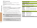
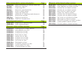


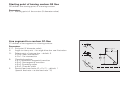
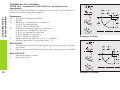


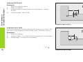
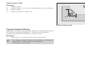
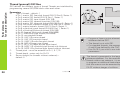

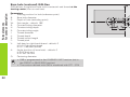


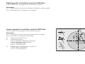
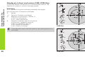
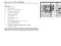
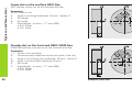
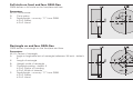

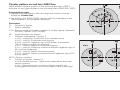
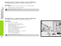


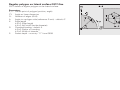

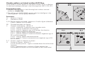


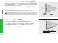

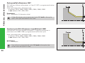
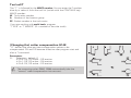
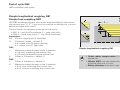

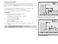
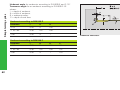

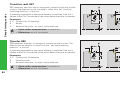

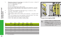
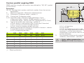

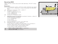


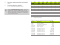
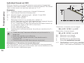
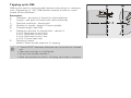
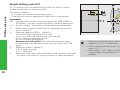
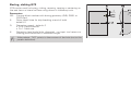
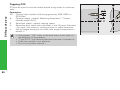

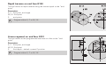
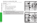


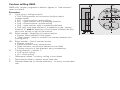
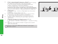
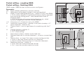

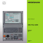
![[1.7 APPLICATION FUNCT.] (FUn](http://vs1.manualzilla.com/store/data/005865551_1-ec59525967aac13e1fcb9d41d71413ed-150x150.png)