1
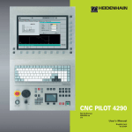
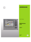
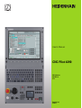
User’s Manual
CNC Pilot 4290
NC Software
625 952-xx
V7.1
English (en)
4/2010
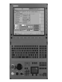
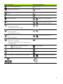
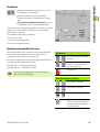
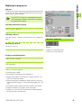
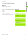
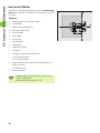
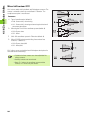
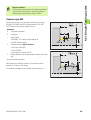
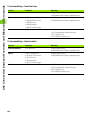
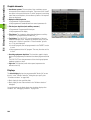
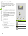
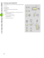
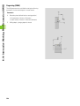
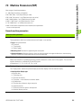
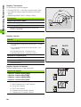
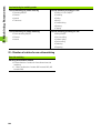
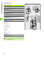
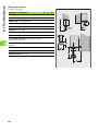
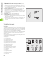
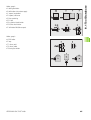
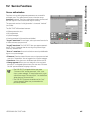
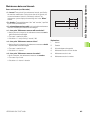
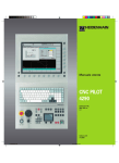
Data input keypad
Machine operating panel
Manual control operating mode
Cycle start
Automatic operating mode
Cycle stop
Programming modes (DIN PLUS, simulation, TURN
PLUS)
Feed rate stop
Organization modes (parameter, service, transfer)
Spindle STOP
Display error status
Spindle on - M3/M4 direction
Call the info system
Spindle jog - M3/M4 direction (The spindle
turns until you press the key.)
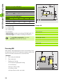
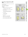
ESC
Manual direction keys +X/–X
Back by one menu level
Close dialog box, do not save data
INS
Manual direction keys +Z/–Z
Insert list element
Close dialog box, save data
ALT
Manual direction keys +Y/–Y
Edits a list element
DEL
Rapid-traverse key
Deletes the list element
Deletes the selected character or the character to the
left of the cursor
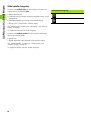
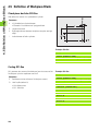
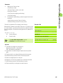
...
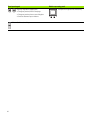
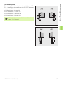
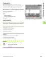
Numerals for entering values and
selecting soft keys
Slide change key
Decimal point
Spindle change key
Minus as algebraic sign
Spindle speed at the programmed value
“Continue key” for special functions (e.g. marking)
Cursor keys
HEIDENHAIN CNC PILOT 4290
Increase/decrease spindle speed by 5%
Override button for feed-rate override
3
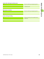
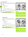
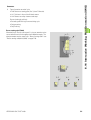
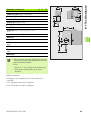
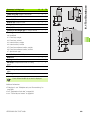
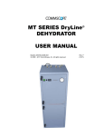
Data input keypad
Page up, Page down (PgUp/PgDn)
Change to previous/next screen page
Change to previous/next screen dialog box
Switches between input windows
Enter – Confirmation of input
4
Machine operating panel
Touchpad with right and left mouse key
CNC PILOT 4290, Software and
Functions
This manual describes functions that are available in the CNC
PILOT 4290 with NC software number 625 (Release 7.1). For
programming the B and Y axes, please refer to the User's Manual
“CNC PILOT 4290 with B and Y Axes”. It is not described in this
manual.
The machine manufacturer adapts the features offered by the control
to the capabilities of the specific lathe by setting machine parameters.
Therefore, some of the functions described in this manual may not be
among the features provided by the CNC PILOT on your machine tool.
CNC PILOT functions that may not be available on your machine
include:
Machining with the C Axis
Machining with the B axis
Machining with the Y-axis
Full-surface machining
Tool monitoring
Graphically supported interactive contour definition
Automatic or graphically supported interactive DIN PLUS program
generation
Please contact your machine manufacturer for detailed information on
the features that are supported by your machine tool.
Many machine manufacturers and HEIDENHAIN offer programming
courses for the CNC PILOT controls. We recommend these courses
as an effective way of improving your programming skill and sharing
information and ideas with other CNC PILOT users.
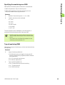
HEIDENHAIN also offers the PC software DataPilot 4290, which is
designed for use with the CNC PILOT 4290. The DataPilot is suitable
for both shop-floor programming as well as off-location program
creation and testing. It is also ideal for training purposes.
Intended place of operation
The CNC PILOT 4290 complies with the limits for a Class A device in
accordance with the specifications in EN 55022, and is intended for
use primarily in industrially-zoned areas.
HEIDENHAIN CNC PILOT 4290
5
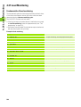
Contents
1
2
3
4
5
6
7
8
9
10
11
Introduction and Fundamentals
Basics of Operation
Manual Control and Automatic Modes
ISO Programming
Graphic Simulation
TURN PLUS
Parameters
Operating Resources
Service and Diagnosis
Transfer
Tables and Overviews
HEIDENHAIN CNC PILOT 4290
7
1 Introduction and Fundamentals ..... 29
1.1 The CNC PILOT ..... 30
Programming ..... 30
The C axis ..... 31
The Y axis ..... 32
Full-surface machining ..... 33
The B axis ..... 34
1.2 The Modes of Operation ..... 35
1.3 Expansion Stages (Options) ..... 37
1.4 Fundamentals ..... 39
Position encoders and reference marks ..... 39
Axis designations and coordinate system ..... 40
Machine reference points ..... 40
Absolute and incremental workpiece positions ..... 41
Units of measure ..... 42
1.5 Tool Dimensions ..... 43
2 Basics of Operation ..... 45
2.1 User Interface ..... 46
Screen displays ..... 46
Controls and displays ..... 47
Selecting the operating mode ..... 48
Data input, selection of functions ..... 48
2.2 Info and Error System ..... 50
The info system ..... 50
Context-sensitive help ..... 52
Direct error messages ..... 52
Error display ..... 53
Additional information on error messages ..... 54
PLC display ..... 54
2.3 Data Backup ..... 55
2.4 Explanation of Terms ..... 56
3 Manual Control and Automatic Modes ..... 57
3.1 Switch-On, Switch-Off, Reference Run ..... 58
Switch-on ..... 58
Reference run for all axes ..... 58
Reference jog for single axis ..... 59
Monitoring EnDat encoders ..... 59
Switch-off ..... 60
HEIDENHAIN CNC PILOT 4290
9
3.2 Manual Control Mode ..... 61
Entering the machine data ..... 62
M commands in Manual Control mode ..... 63
Manual turning operations ..... 64
Handwheel ..... 65
Spindle and manual direction keys ..... 65
Slide/spindle change key ..... 66
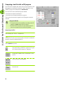
3.3 Table for Tools and Chucking Equipment ..... 67
Setting up a tool list ..... 68
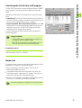
Comparing a tool list with an NC program ..... 70
Transferring the tool list from an NC program ..... 71
Simple tools ..... 71
Tool life management ..... 72
Setting up the chucking table ..... 74
3.4 Setup Functions ..... 75
Setting the tool changing point ..... 75
Shifting the workpiece zero point ..... 76
Defining the protection zone ..... 77
Setting up machine dimensions ..... 78
Tool measurement ..... 79
Calculate the tool compensation ..... 80
3.5 Automatic Mode ..... 81
Program selection ..... 82
Finding a start block ..... 84
Modifying the program run ..... 85
Compensation ..... 87
Tool life management ..... 88
Inspection mode ..... 89
Block display, variable output ..... 93
Graphic display ..... 94
Mechatronic tailstock ..... 95
Post-process measuring status ..... 96
3.6 Machine Display ..... 97
Switching the display ..... 97
Display elements ..... 97
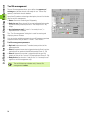
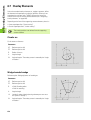
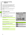
3.7 Load Monitoring ..... 100
Machining using load monitoring ..... 101
Reference machining ..... 102
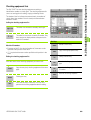
Production using load monitoring ..... 103
Editing limit values ..... 103
Analyzing reference machining ..... 104
Load monitoring parameters ..... 105
10
4 DIN Programming ..... 107
4.1 DIN Programming ..... 108
Introduction ..... 108
DIN PLUS screen ..... 109
Linear and rotary axes ..... 110
Units of measurement ..... 111
Elements of a DIN program ..... 111
4.2 Programming Notes ..... 113
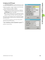
Configuring the DIN editor ..... 113
Parallel editing ..... 114
Selecting submenus, positioning the cursor ..... 114
Making, editing and deleting NC blocks ..... 115
Search functions ..... 116
Conversational or free editing ..... 117
Geometry and machining commands ..... 117
Contour programming ..... 118
List of G functions ..... 120
Address parameters ..... 120
Tool programming ..... 121
Subprograms, expert programs ..... 122
NC program conversion ..... 122
Fixed cycles ..... 123
4.3 The DIN PLUS Editor ..... 124
Overview of main menu ..... 124
Overview of geometry menu ..... 125
Overview of machining menu ..... 126
New NC program ..... 127
NC program management ..... 128
Graphics window ..... 129
Workpiece-blank programming ..... 130
Block numbering ..... 130
Programming instructions ..... 131
Block group menu ..... 133
HEIDENHAIN CNC PILOT 4290
11
4.4 Program Section Code ..... 135
PROGRAM HEAD section ..... 136
TURRET section ..... 137
CHUCKING EQUIPMENT section ..... 142
CONTOUR section ..... 143
BLANK section ..... 143
FINISHED PART section ..... 143
AUXILIARY CONTOUR section ..... 144
FRONT section ..... 144
REAR SIDE section ..... 144
SURFACE section ..... 144
MACHINING section ..... 144
END code ..... 144
ZUORDNUNG [ASSIGNMENT] instruction $.. ..... 144
SUBPROGRAM section ..... 145
RETURN code ..... 145
CONST code ..... 145
4.5 Definition of Workpiece Blank ..... 146
Chuck piece: bar/tube G20-Geo ..... 146
Casting G21-Geo ..... 146
4.6 Basic Contour Elements ..... 147
Starting point of turning contour G0-Geo ..... 147
Line segment in a contour G1-Geo ..... 147
Circular arc of turning contour G2/G3-Geo ..... 148
Circular arc of turning contour G12/G13-Geo ..... 150
4.7 Contour Form Elements ..... 152
Recess (standard) G22-Geo ..... 152
Recess (general) G23-Geo ..... 153
Thread with undercut G24-Geo ..... 155
Undercut contour G25-Geo ..... 156
Thread (standard) G34-Geo ..... 159
Thread (general) G37-Geo ..... 160
Hole (centric) G49-Geo ..... 162
4.8 Attributes for Contour Description ..... 163
Precision stop ..... 164
Surface roughness G10-Geo ..... 164
Feed rate reduction factor G38-Geo ..... 165
Attributes for superimposed elements G39-Geo ..... 165
Blockwise oversize G52-Geo ..... 166
Feed per revolution G95-Geo ..... 166
Additive compensation G149-Geo ..... 167
4.9 C-Axis Contours—Fundamentals ..... 168
Milling contour position ..... 168
Circular pattern with circular slots ..... 169
12
4.10 Front and Rear Face Contours ..... 172
Starting point of front/rear face contour G100-Geo ..... 172
Line segment in front/rear face contour G101-Geo ..... 172
Circular arc in front/rear face contour G102/G103-Geo ..... 173
Bore hole on front/rear face G300-Geo ..... 174
Linear slot on front/rear face G301-Geo ..... 175
Circular slot on front/rear face G302/G303-Geo ..... 175
Full circle on front/rear face G304-Geo ..... 176
Rectangle on front/rear face G305-Geo ..... 176
Eccentric polygon on front/rear face G307-Geo ..... 177
Linear pattern on front/rear face G401-Geo ..... 177
Circular pattern on front/rear face G402-Geo ..... 178
4.11 Lateral Surface Contours ..... 179
Starting point of lateral surface contour G110-Geo ..... 179
Line segment in a lateral surface contour G111-Geo ..... 179
Circular arc in lateral surface contour G112-/G113-Geo ..... 180
Hole on lateral surface G310-Geo ..... 181
Linear slot on lateral surface G311-Geo ..... 182
Circular slot on lateral surface G312/G313-Geo ..... 182
Full circle on lateral surface G314-Geo ..... 183
Rectangle on lateral surface G315-Geo ..... 183
Eccentric polygon on lateral surface G317-Geo ..... 184
Linear pattern on lateral surface G411-Geo ..... 185
Circular pattern on lateral surface G412-Geo ..... 186
4.12 Tool Positioning ..... 187
Rapid traverse G0 ..... 187
Setting the tool change position G14 ..... 187
Rapid traverse to machine coordinates G701 ..... 188
4.13 Simple Linear and Circular Movements ..... 189
Linear path G1 ..... 189
Circular path G2/ G3 ..... 190
Circular path G12/ G13 ..... 191
4.14 Feed Rate and Spindle Speed ..... 192
Rotational speed limiting G26 ..... 192
Acceleration (slope) G48 ..... 192
Interrupted feed G64 ..... 193
Feed per minute for rotary axes G192 ..... 193
Feed per tooth Gx93 ..... 194
Constant feed rate G94 (feed per minute) ..... 194
Feed per revolution Gx95 ..... 194
Constant surface speed Gx96 ..... 195
Speed Gx97 ..... 195
HEIDENHAIN CNC PILOT 4290
13
4.15 Tool-Tip and Cutter Radius Compensation ..... 196
G40: Switch off TRC/MCRC ..... 197
G41/G42: Switch on TRC/MCRC ..... 197
4.16 Zero Point Shifts ..... 198
Zero point shift G51 ..... 199
Parameter-dependent zero offset G53, G54, G55 ..... 199
Additive zero point shift G56 ..... 200
Absolute zero point shift G59 ..... 201
Mirror/shift contour G121 ..... 202
4.17 Oversizes ..... 204
Switch off oversize G50 ..... 204
Axis-parallel oversize G57 ..... 204
Contour-parallel oversize (equidistant) G58 ..... 205
4.18 Safety Clearances ..... 206
Safety clearance G47 ..... 206
Safety clearance G147 ..... 206
4.19 Tools, Types of Compensation ..... 207
Tool call – T ..... 207
(Changing the) tool edge compensation G148 ..... 208
Additive compensation G149 ..... 209
Compensation of right-hand tool tip G150
Compensation of left-hand tool tip G151 ..... 210
Adding tool dimensions G710 ..... 211
4.20 Contour-Based Turning Cycles ..... 212
Working with cycles ..... 212
Longitudinal roughing G810 ..... 212
Face roughing G820 ..... 215
Contour-parallel roughing G830 ..... 218
Contour-parallel with neutral tool G835 ..... 220
Recessing G860 ..... 222
Recessing cycle G866 ..... 224
Recess turning cycle G869 ..... 225
Finish contour G890 ..... 228
4.21 Simple Turning Cycles ..... 231
End of cycle G80 ..... 231
Simple longitudinal roughing G81 ..... 231
Simple face roughing G82 ..... 232
Simple contour repeat cycle G83 ..... 234
Undercut cycle G85 ..... 235
Recessing G86 ..... 236
Radius cycle G87 ..... 238
Chamfer cycle G88 ..... 238
14
4.22 Thread Cycles ..... 239
Thread switch G933 ..... 239
Thread cycle G31 ..... 240
Simple thread cycle G32 ..... 242
Thread single path G33 ..... 244
4.23 Drilling Cycles ..... 246
Drilling cycle G71 ..... 246
Boring, countersinking G72 ..... 248
Tapping G73 ..... 249
Tapping G36 ..... 250
Deep-hole drilling G74 ..... 251
4.24 C-Axis Commands ..... 253
No. of C axis G119 ..... 253
Reference diameter G120 ..... 253
Zero point shift, C axis G152 ..... 254
Standardize C axis G153 ..... 254
4.25 Front/Rear-Face Machining ..... 255
Rapid traverse on front/rear face G100 ..... 255
Linear segment on front/rear face G101 ..... 256
Circular arc on front/rear face G102/G103 ..... 257
4.26 Lateral Surface Machining ..... 258
Rapid traverse, lateral surface G110 ..... 258
Line segment on lateral surface G111 ..... 259
Circular arc on lateral surface G112/G113 ..... 260
4.27 Milling Cycles ..... 261
Contour milling G840—Fundamentals ..... 261
Pocket milling, roughing G845 – Fundamentals ..... 270
Pocket milling, finishing G846 ..... 276
Thread milling, axial G799 ..... 278
Engraving on front face G801 ..... 279
Engraving on lateral surface G802 ..... 280
Character set for engraving ..... 280
HEIDENHAIN CNC PILOT 4290
15
4.28 Assignment, Synchronization, Workpiece Transfer ..... 282
Converting and mirroring G30 ..... 282
Spindle with workpiece G98 ..... 283
Workpiece group G99 ..... 284
One-sided synchronization G62 ..... 284
Synchronization marking G162 ..... 285
Synchronous start of slides G63 ..... 285
M97 Synchronous function ..... 286
Spindle synchronization G720 ..... 286
C-angle offset G905 ..... 287
Measuring angular offset during spindle synchronization G906 ..... 288
Traversing to a fixed stop G916 ..... 288
Controlled parting using lag error monitoring G917 ..... 291
Controlled parting using spindle monitoring G991 ..... 292
Values for controlled parting G992 ..... 293
4.29 Contour Follow-Up ..... 294
Saving/loading contour follow-up G702 ..... 294
Contour follow-up G703 ..... 294
K default branch G706 ..... 295
4.30 In-process and Post-process Measuring ..... 296
In-process measuring ..... 296
Post-process measurement G915 ..... 298
4.31 Load Monitoring ..... 300
Fundamentals of load monitoring ..... 300
Specifying the monitoring zone G995 ..... 301
Type of monitoring G996 ..... 301
16
4.32 Other G Functions ..... 302
Period of dwell G4 ..... 302
Precision stop G7 ..... 302
Precision stop off G8 ..... 302
Precision stop G9 ..... 302
Move rotary axis G15 ..... 303
Switch off protection zone G60 ..... 303
Chucking equipment in simulation G65 ..... 304
Component position G66 ..... 305
Waiting for time G204 ..... 305
Update nominal values G717 ..... 305
Move lag error G718 ..... 306
Actual values in variables G901 ..... 306
Zero-point shift in variables G902 ..... 306
Lag error in variables G903 ..... 306
Block speed monitoring off G907 ..... 306
Feed rate override 100% G908 ..... 307
Interpreter stop G909 ..... 307
Velocity feedforward G918 ..... 307
Spindle override 100% G919 ..... 307
Deactivate zero-point shifts G920 ..... 308
Deactivate zero-point shifts, tool lengths G921 ..... 308
T no. internal G940 ..... 308
Transferring magazine compensation values G941 ..... 309
Servo lag limit G975 ..... 309
Activating zero-point shifts G980 ..... 309
Activate zero-point shifts, tool lengths G981 ..... 310
Sleeve monitoring G930 ..... 310
Shaft speed with V constant G922 ..... 311
4.33 Data Input and Data Output ..... 312
Output window for # variables WINDOW ..... 312
Input of # variables INPUT ..... 312
Output of # variables PRINT ..... 313
V variable simulation ..... 313
Output window for V variables WINDOWA ..... 313
Input of V variables INPUTA ..... 314
Output of V variables PRINTA ..... 314
4.34 Programming with Variables ..... 315
# variables ..... 316
V variables ..... 318
HEIDENHAIN CNC PILOT 4290
17
4.35 Conditional Block Run ..... 322
Program branching IF..THEN..ELSE..ENDIF ..... 322
WHILE..ENDWHILE program repeat ..... 323
SWITCH..CASE—program branching ..... 324
Skip level /.. ..... 326
Slide code $.. ..... 326
4.36 Subprograms ..... 327
Subprogram call: L"xx" V1 ..... 327
Dialog texts in subprogram call ..... 328
Help graphics for subprogram calls ..... 329
4.37 M Commands ..... 330
M commands for program-run control ..... 330
Machine commands ..... 331
4.38 Lathes with Multiple Slides ..... 332
Multi-slide programming ..... 332
Program run ..... 334
Positioning the steady rest ..... 334
Traveling steady rest ..... 336
Two slides work simultaneously ..... 338
Two slides work in succession ..... 340
Machining with four-axis cycle ..... 342
4.39 Full-surface machining ..... 344
Fundamentals of full-surface machining ..... 344
Programming of full-surface machining ..... 345
Full-surface machining with opposing spindle ..... 346
Full-surface machining with single spindle ..... 349
4.40 DIN PLUS Program Example ..... 351
Example of a subprogram with contour repetitions ..... 351
4.41 DIN PLUS Templates ..... 354
Starting templates ..... 354
Structure templates ..... 354
Design of structure templates ..... 355
Transfer parameters for structure templates ..... 355
Editing structure templates ..... 356
Help graphics for structure templates ..... 356
Template menu ..... 356
Template example ..... 357
4.42 Connection between Geometry and Machining Commands ..... 359
Turning ..... 359
C-axis machining – front/rear face ..... 360
C-axis machining – lateral surface ..... 360
18
5 Graphic Simulation ..... 361
5.1 Simulation Mode of Operation ..... 362
Screen layout, soft keys ..... 363
Graphic elements ..... 364
Displays ..... 364
Zero point shifts ..... 366
Path display ..... 367
Simulation window ..... 368
Setting the simulation window ..... 369
Configuring the simulation ..... 370
Adjusting the section (zoom function) ..... 371
Errors and warnings ..... 372
How to activate the simulation function ..... 372
Simulation mode ..... 373
5.2 Contour Simulation ..... 374
Functions of the contour simulation ..... 374
Contour dimensioning ..... 375
5.3 Machining Simulation ..... 376
Checking the workpiece machining ..... 376
Protection zone and limit switch monitoring (machining simulation) ..... 377
Dynamic limit switch monitoring ..... 377
Contour checking ..... 378
Saving the generated contour ..... 378
Displaying the tool tip reference point ..... 379
5.4 Motion Simulation ..... 380
Real-time simulation ..... 380
Protection zone and limit switch monitoring (motion simulation) ..... 381
Contour checking ..... 381
5.5 3-D View ..... 382
Influencing the 3-D view ..... 382
5.6 Debugging Functions ..... 383
Simulation with starting block ..... 383
Displaying variables ..... 384
Editing variables ..... 385
5.7 Checking Multi-channel Programs ..... 386
5.8 Time Calculation, Synchronous Point Analysis ..... 387
Time Calculation ..... 387
Synchronous point analysis ..... 388
HEIDENHAIN CNC PILOT 4290
19
6 TURN PLUS ..... 389
6.1 TURN PLUS Mode of Operation ..... 390
TURN PLUS concept ..... 390
TURN PLUS files ..... 391
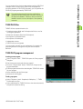
TURN PLUS program management ..... 391
Operating notes ..... 392
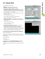
6.2 Program Head ..... 393
Generating programs for automatic lathes ..... 394
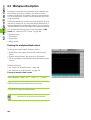
6.3 Workpiece Description ..... 396
Entering the workpiece blank contour ..... 396
Entering the finished part contour ..... 397
Superimposing form elements ..... 398
Integrating overlay elements ..... 399
Entering contours machined with the C axis ..... 400
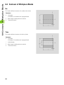
6.4 Contours of Workpiece Blanks ..... 402
Bar ..... 402
Tube ..... 402
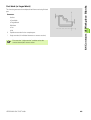
Cast blank (or forged blank) ..... 403
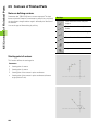
6.5 Contours of Finished Parts ..... 404
Notes on defining contours ..... 404
Starting point of contour ..... 404
Linear elements ..... 405
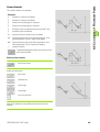
Circular element ..... 406
6.6 Form Elements ..... 408
Chamfer ..... 408
Rounding ..... 408
Undercut type E ..... 409
Undercut type F ..... 409
Undercut type G ..... 409
Undercut type H ..... 410
Undercut type K ..... 410
Undercut type U ..... 410
Recess general ..... 411
Recess type D (sealing ring) ..... 412
Relief turn (type FD) ..... 413
Recess type S (guarding ring) ..... 413
Thread ..... 414
(Centric) Hole ..... 415
6.7 Overlay Elements ..... 418
Circular arc ..... 418
Wedge/rounded wedge ..... 418
Pontoon ..... 419
Linear superimposition (“linear overlay”) ..... 419
Circular superimposition (“circular overlay”) ..... 420
20
6.8 C-Axis Contours ..... 421
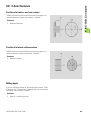
Position of a front or rear face contour ..... 421
Position of a lateral surface contour ..... 421
Milling depth ..... 421
Entering the C-axis contour dimensions ..... 422
Front or rear face: Starting point ..... 422
Front or rear face: Linear element ..... 423
Front or rear face: Circular element ..... 424
Front or rear face: Single hole ..... 426
Front or rear face: Circle (full circle) ..... 428
Front or rear face: Rectangle ..... 429
Front or rear face: Polygon ..... 430
Front or rear face: Linear slot ..... 431
Front or rear face: Circular slot ..... 432
Front or rear face: Linear hole or figure pattern ..... 433
Front or rear face: Circular hole or figure pattern ..... 434
Lateral surface: Starting point ..... 435
Lateral surface: Linear element ..... 436
Lateral surface: Circular element ..... 437
Lateral surface: Single hole ..... 438
Lateral surface: Circle (full circle) ..... 440
Lateral surface: Rectangle ..... 441
Lateral surface: Polygon ..... 442
Lateral surface: Linear slot ..... 443
Lateral surface: Circular slot ..... 444
Lateral surface: Linear hole or figure pattern ..... 445
Lateral surface: Circular hole or figure pattern ..... 446
6.9 Help Functions ..... 447
Unresolved contour elements ..... 447
Selections ..... 448
Zero point shift ..... 452
Copying a contour section in linear series ..... 452
Copying a contour section in circular series ..... 453
Copying a contour section by mirroring ..... 453
Calculator ..... 454
Digitizing ..... 455
Checking contour elements (inspector) ..... 456
Error messages ..... 457
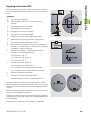
6.10 Importing of DXF Contours ..... 458
Fundamentals for DXF import ..... 458
Configuring the DXF Import ..... 459
DXF import ..... 460
HEIDENHAIN CNC PILOT 4290
21
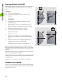
6.11 Manipulating Contours ..... 461
Editing the contours of a blank part ..... 461
Deleting contour elements ..... 462
Editing contour elements or form elements ..... 462
Adding a contour or contour element ..... 463
Closing the contour ..... 464
Resolving a contour ..... 464
Trimming – Linear element ..... 465
Trimming – Length of contour ..... 466
Trimming – Radius of arc ..... 466
Trimming – Diameter of linear element ..... 467
Transformations – Fundamentals ..... 467
Transformations – Shifting ..... 468
Transformations – Rotating ..... 468
Transformations – Mirroring ..... 469
Transformations – Inverting ..... 469
6.12 Assigning Attributes ..... 470
Attributes for workpiece blanks ..... 470
Attributes – Oversize ..... 471
Attributes – Feed rate ..... 472
Attributes – Peak-to-valley ..... 472
Attributes – Additive compensation ..... 473
Machining attributes – Measure ..... 473
Machining attributes – Threading ..... 474
Machining attributes – Drill – Retraction plane ..... 475
Machining attributes – Drilling combinations ..... 475
Machining attributes – Contour milling ..... 476
Machining attributes – Area milling ..... 477
Machining attributes – Deburring ..... 478
Machining attributes – Engraving ..... 479
Machining attributes – Precision stop ..... 479
Machining attributes – Separation point ..... 480
Attributes – Exclusion from machining ..... 480
Deleting machining attributes ..... 481
22
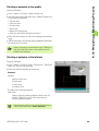
6.13 Preparing a Machining Process ..... 482
Preparing a machining process – Fundamentals ..... 482
Chucking a workpiece at the spindle ..... 483
Chucking a workpiece at the tailstock ..... 483
Defining the cutting limit ..... 484
Deleting the chucking data ..... 484
Rechuck – Standard machining ..... 485
Rechuck – 1st setup after 2nd setup ..... 486
Parameters for two-jaw, three-jaw or four-jaw chucks ..... 488
Collet chuck parameters ..... 489
Parameters for face drivers (“without chuck”) ..... 489
Parameters for face drivers with jaws (“Three-jaw chuck indirect”) ..... 490
Setting up and managing tool lists ..... 490
HEIDENHAIN CNC PILOT 4290
23
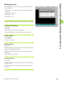
6.14 Interactive Working Plan Generation (IWG) ..... 494
Working plan exists ..... 495
Generating a work block ..... 496
Calling a tool ..... 497
Cutting data ..... 497
Cycle specification ..... 498
Overview of roughing operations ..... 499
Roughing longitudinal (G810) ..... 500
Roughing transverse (G820) ..... 501
Roughing contour-parallel (G830) ..... 502
Residual roughing – longitudinal ..... 503
Residual roughing – transverse ..... 504
Residual roughing – contour-parallel ..... 505
Roughing hollowing – neutral tool (G835) ..... 506
Overview of recessing operations ..... 507
Contour recessing radial/axial (G860) ..... 508
Recessing radial/axial (G866) ..... 509
Recess turning radial/axial (G869) ..... 510
Parting ..... 512
Parting and workpiece transfer ..... 513
Overview of drilling operations ..... 516
Centric predrilling (G74) ..... 517
Centering, countersinking (G72) ..... 518
Drilling, reaming, deep-hole drilling ..... 519
Tapping ..... 520
Finishing ..... 521
Finishing – Clearance turning ..... 524
Finishing – undercut ..... 524
Thread machining (G31) ..... 525
Overview of milling operations ..... 526
Contour milling – Roughing/Finishing (G840) ..... 527
Deburring (G840) ..... 529
Engraving (G840) ..... 530
Pocket milling – Roughing/Finishing (G845/G846) ..... 531
Special machining (SM) ..... 532
6.15 Automatic Working Plan Generation (AWG) ..... 534
Generating a working plan ..... 534
Machining sequence – Fundamentals ..... 535
Editing and managing machining sequences ..... 536
Overview of machining sequences ..... 538
6.16 Control Graphics ..... 547
Adjusting the section (zoom function) ..... 547
Setting the control graphics ..... 548
24
6.17 Configuring TURN PLUS ..... 549
General settings ..... 549
Configuring windows (views) ..... 550
Configuring the control graphics ..... 550
Setting the coordinate system ..... 551
6.18 Machining Information ..... 552
Tool selection, turret assignment ..... 552
Contour recessing, recess turning ..... 553
Drilling ..... 553
Cutting data, coolant ..... 553
Hollowing ..... 554
Inside contours ..... 555
Drilling ..... 556
Shaft machining ..... 557
Multi-slide machines ..... 559
Full-surface machining ..... 560
6.19 Example ..... 562
Creating a program ..... 562
Defining the workpiece blank ..... 563
Defining the basic contour ..... 563
Defining form elements ..... 564
Preparing the machining process, chucking ..... 565
Generating and saving a working plan ..... 565
7 Parameters ..... 567
7.1 The Parameter Mode of Operation ..... 568
7.2 Editing Parameters ..... 569
Current parameters ..... 569
Parameter lists ..... 569
Editing configuration parameters ..... 570
7.3 Machine Parameters (MP) ..... 571
General machine parameters ..... 571
Machine parameters for slides ..... 572
Machine parameters for spindles ..... 573
Machine parameters for C axes ..... 574
Machine parameters for linear axes ..... 575
7.4 Control Parameters ..... 577
General control parameters ..... 577
Control parameters for simulation ..... 579
Control parameters for machine display ..... 580
7.5 Set-Up Parameters ..... 583
HEIDENHAIN CNC PILOT 4290
25
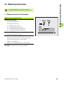
7.6 Machining Parameters ..... 585
1 – Global parameters for finished parts ..... 585
2 – Global technology parameters ..... 586
3 – Centric predrilling ..... 588
4 – Roughing ..... 591
5 – Finishing ..... 594
6 – Recessing and contour recessing ..... 597
7 – Thread cutting ..... 599
8 – Measuring ..... 600
9 – Drilling ..... 600
10 – Milling ..... 602
Load monitoring ..... 603
20 – Direction of rotation for rear-side machining ..... 604
21 – Name of the subroutines ..... 605
22 – Sequence of tool selection ..... 605
23 – Template management ..... 606
24 – Parameter of the rechucking subroutines ..... 606
8 Operating Resources ..... 607
8.1 Tool Database ..... 608
Tool editor ..... 608
Overview of tool types ..... 612
Tool parameters ..... 614
Tool holder, tool mount ..... 624
8.2 Database for Chucking Equipment ..... 628
Chucking equipment editor ..... 628
Chucking equipment lists ..... 629
Chucking equipment data ..... 630
8.3 Technology Database ..... 641
Editing the technology data ..... 642
Cutting-value tables ..... 643
26
9 Service and Diagnosis ..... 645
9.1 The Service Mode of Operation ..... 646
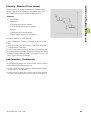
9.2 Service Functions ..... 647
Access authorization ..... 647
System service ..... 648
Fixed-word lists ..... 649
9.3 Maintenance System ..... 650
Maintenance dates and intervals ..... 651
Displaying maintenance actions ..... 652
9.4 Diagnosis ..... 655
Information and display ..... 655
Log files and network settings ..... 656
Software update ..... 657
10 Transfer ..... 659
10.1 The Transfer Mode of Operation ..... 660
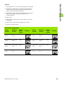
Overview of data transfer methods ..... 661
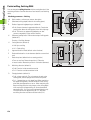
Configuring Windows networks ..... 663
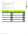
Configuring the serial interface or “printer” ..... 666
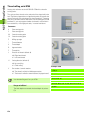
10.2 Data Transfer ..... 668
Enabling, file types ..... 668
Basics of operation ..... 669
Transmitting and receiving files ..... 671
10.3 Parameters and Operating Resources ..... 674
Transmitting parameters/operating resources ..... 675
Loading parameters/operating resources ..... 676
Backing up and restoring data ..... 677
Viewing parameter, operating-resource or backup files ..... 679
10.4 File Organization ..... 680
Fundamentals for file organization ..... 680
Managing files ..... 681
HEIDENHAIN CNC PILOT 4290
27
11 Tables and Overviews ..... 683
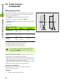
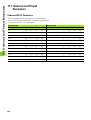
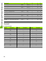
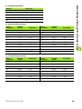
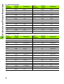
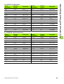
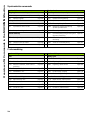
11.1 Undercut and Thread Parameters ..... 684
Undercut DIN 76, Parameters ..... 684
Undercut DIN 509 E, Parameters ..... 686
Undercut DIN 509 F, Parameters ..... 686
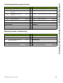
Thread Parameters ..... 687
Thread pitch ..... 688
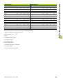
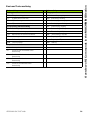
11.2 Pin Layouts and Connecting Cables for the Data Interfaces ..... 694
RS-232-C/V.24 interface for HEIDENHAIN devices ..... 694
Non-HEIDENHAIN devices ..... 695
RS-422/V.11 interface ..... 696
Ethernet interface RJ45 socket ..... 696
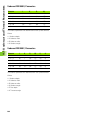
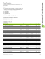
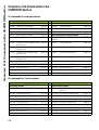
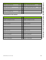
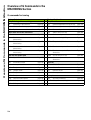
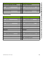
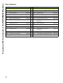
11.3 Technical Information ..... 697
Specifications ..... 697
Accessories ..... 698
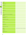
User functions ..... 698
28
Introduction and
Fundamentals
HEIDENHAIN CNC PILOT 4290
29
1.1 The CNC PILOT
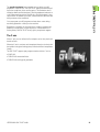
1.1 The CNC PILOT
The CNC PILOT is a contouring control designed for complex lathes
and turning centers. In addition to turning operations, the control can
also perform milling, drilling and boring operations. The C, Y and B
axes enable you to drill and mill on the front and rear faces, the lateral
surface and oblique planes. And as always, the CNC PILOT supports
full-surface machining with dual-spindles.
The CNC PILOT controls up to six slides, four spindles, two C axes,
one B axis and a pocket-oriented tool magazine. The control can
machine up to four workpieces simultaneously.
Programming
Depending on the type and complexity of the parts to be machined
and your organization, you can choose the type of programming best
suited to your tasks.
In TURN PLUS you describe the contour of the blank and finished part
using interactive graphics. Then you call the automatic working plan
generation (AWG), and the NC program will be generated fully
automatically on a keystroke. An alternative is the interactive working
plan generation (IWG). When using the IWG, you determine the
sequence of machining and other technical details.
Every working step is shown in the control graphics and can be
corrected immediately. The result of program creation with TURN
PLUS is a structured DIN PLUS program.
TURN PLUS minimizes the number of entries required, but it requires
that the the tool data and cutting data has already been entered.
If TURN PLUS fails to create the optimal NC program for
technologically sophisticated machining operations, or if you
primarily want to reduce the machining time, write the NC program
with DIN PLUS.
In DIN PLUS you first describe the contour of the workpiece blank and
finished part. The “simplified geometry programming” calculates
nondimensioned coordinates if, for example, the drawing is not
dimensioned for conventional NC. Then you write the NC program
using powerful fixed cycles.
Both TURN PLUS and DIN PLUS support a C or Y axis and full-surface
machining. DIN PLUS cycles are available for working with the B axis.
As an alternative, you can machine your workpiece in DIN PLUS with
linear and circular movements and simple turning cycles, as you are
accustomed to in conventional DIN programming.
30
1.1 The CNC PILOT
The graphic simulation feature enables you to subject your NC
programs to a realistic test. The CNC PILOT displays the machining of
up to four workpieces in the working space. The simulation shows
workpiece blanks and finished parts, chucking equipment and tools to
scale. When working with the tilted B axis, the working plane is also
shown tilted. This enables you to see, without distortion, the holes and
milling contours to be machined.
You can program your NC programs and test them—even during
machining operations—directly on the machine.
Regardless of whether you are machining a simple or complex part,
producing a single part or a series of parts, or a whole batch on a
turning center, the CNC PILOT always gives you optimum support.
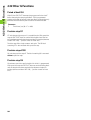
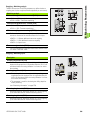
The C axis
With a C axis you can drill and mill a workpiece on its front, back and
lateral surfaces.
When the C axis is used, one axis interpolates linearly or circularly with
the spindle in the given working plane, while the third axis interpolates
linearly.
The CNC PILOT supports part program creation with the C axis in:
DIN PLUS
TURN PLUS contour definition
TURN PLUS working plan generation
HEIDENHAIN CNC PILOT 4290
31
1.1 The CNC PILOT
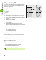
The Y axis
With a Y axis you can drill and mill a workpiece on its front, back and
lateral surfaces.
During use of the Y-axis, two axes interpolate linearly or circularly in
the given working plane, while the third axis interpolates linearly. This
enables you to machine slots or pockets, for example, with plane
floors and perpendicular edges. By defining the spindle angle, you can
determine the position of the milling contour on the workpiece.
The CNC PILOT supports part program creation with the Y axis in:
DIN PLUS
TURN PLUS contour definition
TURN PLUS working plan generation
32
1.1 The CNC PILOT
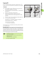
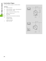
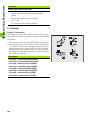
Full-surface machining
Functions like angle-synchronous part transfer with rotating spindle,
traversing to a stop, controlled parting, and coordinate transformation
ensures efficient machining as well as simple programming of fullsurface machining.
The functions for full-surface machining are available in:
DIN PLUS
TURN PLUS contour definition
TURN PLUS working plan generation
The CNC PILOT supports full-surface machining for all common
machine designs.
Examples: Lathes with
Rotating gripper
Movable opposing spindle
Several spindles, slides and tool carriers
HEIDENHAIN CNC PILOT 4290
33
1.1 The CNC PILOT
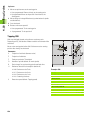
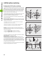
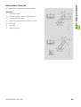
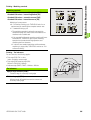
The B axis
The B axis makes it possible to drill, bore and mill in oblique planes.
To make programming easy, the coordinate system is tilted in such a
way that you can define the drilling patterns and milling contours in the
YZ plane. The actual drilling or milling operation is then performed in
the tilted plane.
During work on the tilted plane, the tool is perpendicular to the plane.
The tilting angle of the B axis and the angle of the tilted plane are
identical.
Another advantage of the B axis is the flexible use of tools during
turning operations. By tilting the B axis and rotating the tool you can
bring it into positions that enable you to use one and the same tool to
machine in the longitudinal and transverse (or radial and axial)
directions on the main and opposing spindles.
In this way, you need fewer tools and fewer tool changes.
The CNC PILOT supports part program creation with the B axis in
DIN PLUS.
The graphical simulation shows the machining operation in a tilted
working plane in the familiar lathe and front windows, as well as in the
“side view (YZ).”
User's Manual for the B and Y axes
The manual and automatic control functions a well as the
programming and testing of NC programs for the B and Y
axes are described in a separate User's Manual. Please
contact HEIDENHAIN if you require a copy of this User's
Manual.
34
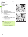
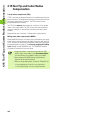
1.2 The Modes of Operation
1.2 The Modes of Operation
Operating modes
Manual mode: In the Manual Control mode you set up
the machine and move the axes manually.
Automatic mode: NC in Automatic mode, NC programs
are executed from start to end. You control and monitor
the machining of the workpieces.
DIN PLUS programming mode: You write the
structured NC programs in DIN PLUS. First you define
the geometry of the blank and finished part, and then
program the machining of the workpiece.
Simulation programming mode: The Simulation mode
graphically depicts contours, tool movements and cutting
processes. The working space, tools and chucking
equipment are shown true to scale.
During simulation, the CNC PILOT calculates the
machining and idle-machine times for every tool. For
lathes with several slides, the synchronous point
analysis enables you to optimize your NC program.
TURN PLUS programming mode: In TURN PLUS you
describe the workpiece contour interactively in a graphic.
If you then define the material and chucking equipment,
the Automatic Working plan Generation (AWG) will
generate the NC program automatically at a keystroke.
As an alternative, you can create the working plan with
the aid of interactive graphics (IAG).
Parameter organization mode: The system behavior of
the CNC PILOT is controlled by parameters. In this mode,
you set the parameters to adapt the control to your
situation.
In addition, in this mode you describe the operating
resources (tools and chucking equipment) and the
cutting values.
HEIDENHAIN CNC PILOT 4290
35
1.2 The Modes of Operation
Operating modes
Service organization mode: In Service you log in for
password-protected functions, select the conversational
language and make system settings. This operating
mode also provides diagnostic functions for
commissioning and checking the system.
Transfer organization mode: In Transfer, you exchange
data with other systems, organize your programs and
back-up your data.
The actual control is not accessible to the machinist. You should know,
however, that your CNC PILOT stores all TURN PLUS and DIN PLUS
programs that you enter on an integrated hard disk. This allows you to
save a vast number of programs.
For data exchange and data backup, you can use the Ethernet
interface and the USB memory medium. Data exchange on the basis
of the serial interface (RS-232) is also possible.
36
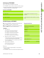
1.3 Expansion Stages (Options)
1.3 Expansion Stages (Options)
The machine manufacturer configures the CNC PILOT according to
the capabilities of the specific lathe. The following upgrades (options)
are available, which enable you to adapt the control to your specific
requirements:
TURN PLUS – Basis (ID 354 132-01):
Graphically supported interactive contour definition
Graphic program entry for describing the workpiece blank and
finished part
Geometry program for calculating and depicting contour points for
which dimensional data are missing
Simple entry of standardized form elements such as chamfers,
rounding arcs, undercuts, recesses, threads, fits
Simple handling of transformations such as datum shift, rotation,
mirroring, duplication
Graphically supported interactive DIN PLUS program generation
Individual selection of the operating mode
Selection of the tool and specification of cutting data
Direct graphic verification of the metal removing operation
Direct compensation capability
Automatic DIN PLUS program generation
Automatic tool selection
Automatic generation of the working plan
TURN PLUS – C-axis option (ID 354 133-01):
Depiction of programming in the XC plane (front/rear face) and ZC
plane (unrolled lateral surface view)
Hole pattern and figure pattern; any milled contours
Interactive or automatic generation of the working plan, including Caxis machining
TURN PLUS – option for opposing spindles
(ID 354 134-01):
Rechucking with expert program
Interactive or automatic generation of the working plan, including
rechucking and machining the second setup
TURN PLUS – DXF import (ID 526 461-01):
In TURN PLUS, read in the contours (blank and finished part
contours, milled contours, contour trains) that are available in DXF
format
View and select DXF layers
Load DXF contour into TURN PLUS
HEIDENHAIN CNC PILOT 4290
37
1.3 Expansion Stages (Options)
Opposing spindle—full-surface machining of a workpiece
(ID 518 289-01):
Spindle synchronism (G720)
Parting control (G917, G991, G992)
Traversing to a dead stop (G916)
Mirroring and converting (G30)
In-process measurement—measuring on the machine
(ID 354 536-01):
With touch trigger probe
For tool setup
For workpiece measurement
Post-process measurement—measuring on external measuring
stations
(ID 354 537-01):
Connecting the measuring equipment over the RS-232 interface
Evaluating the measurement results in the NC program
Y axis (ID 354 138-01)
Support of Y axis programming in DIN PLUS, TURN PLUS and in
simulation
Depiction of programming in the XY (front/rear face) and YZ (lateral
surface view) planes
DIN PLUS and TURN PLUS: Drilling, boring and figure patterns; any
milling contours
DIN PLUS: Cycles for drilling, boring and milling
TURN PLUS: Interactive or automatic generation of the working
plan, including Y-axis machining
B axis (ID 589 963-01)
Support of B axis programming in DIN PLUS and in simulation
The coordinate system is transformed to a tilted place in order to
describe hole and figure patterns as well as any desired contours in
the YZ plane
Fixed cycles work in a tilted plane
Options can usually be retrofitted. Your machine manufacturer can
give you more information.
This description covers all options. The operating
sequences described in this manual may therefore deviate
from those on your machine whenever a certain option is
not supported by your system.
38
1.4 Fundamentals
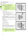
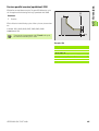
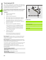
1.4 Fundamentals
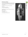
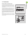
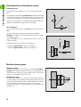
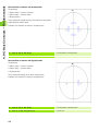
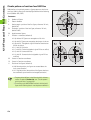
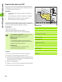
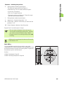
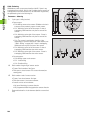
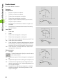
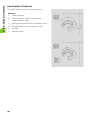
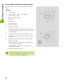
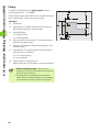
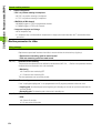
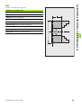
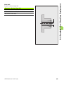
Position encoders and reference marks
The machine axes are equipped with position encoders that register
the positions of the slide or tool. When a machine axis moves, the
corresponding position encoder generates an electrical signal. The
control evaluates this signal and calculates the precise actual position
of the machine axis.
XMP
If there is a power interruption, the calculated position will no longer
correspond to the actual position of the machine slide. To recover this
association, incremental position encoders are provided with
reference marks. The scales of the position encoders contain one or
more reference marks that transmit a signal to the control when they
are crossed over. From the signal the CNC PILOT can re-establish the
assignment of displayed positions to machine positions. For linear
encoders with distance-coded reference marks the machine axes
need to move by no more than 20 mm, for angle encoders by no more
than 20°.
X (Z,Y)
With absolute encoders, an absolute position value is transmitted to
the control immediately upon switch-on. In this way the assignment
of the actual position to the machine slide position is re-established
directly after switch-on.
Zref
Xref
M
HEIDENHAIN CNC PILOT 4290
39
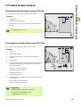
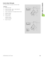
1.4 Fundamentals
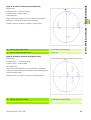
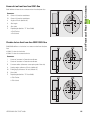
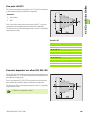
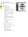
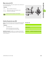
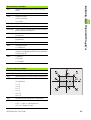
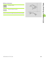
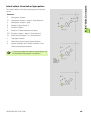
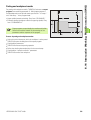
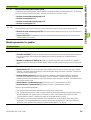
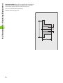
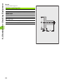
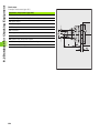
Axis designations and coordinate system
Coordinate system
The meanings of the coordinates X, Y, Z, B, C are specified in DIN
66 217.
+Y
The coordinates entered for the principle axes X and Z are referenced
to the workpiece zero point. The angular data for the rotary axes B and
C are given with respect to the zero point of the respective rotary axis.
+X
+B
On lathes, C axis movements are realized by turning the workpiece
and B axis movements by tilting the tool (swivel head).
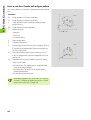
Axis designations
+C
The cross slide is referred to as the X axis and the saddle as the Z
axis.
+Z
All X-axis values that are displayed or entered are regarded as
diameters. In TURN PLUS you can define whether the X axis values
are diameters or radii.
Lathes with Y axis: The Y axis is perpendicular to the X axis and Z axis
(Cartesian system).
X+
When programming paths of traverse, remember to:
Program a positive value to depart the workpiece.
Program a negative value to approach the workpiece.
Y+
X
M
Z
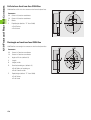
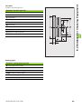
Machine reference points
Machine zero point
The point of intersection of the X and Z axes is called the machine
zero point. On a lathe, the machine zero point is usually the point of
intersection of the spindle axis and the spindle surface. The machine
zero point is designated with the letter “M”.
Workpiece zero point
For machining a workpiece, it is easier to reference all input data to a
zero point located on the workpiece. By programming the zero point
used in the workpiece drawing, you can take the dimensions directly
from the drawing, without further calculation. This point is the
“workpiece zero point.” The workpiece zero point is designated with
the letter “W”.
40
Z+
1.4 Fundamentals
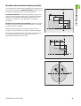
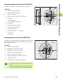
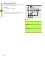
Absolute and incremental workpiece positions
If the coordinates of a position are referenced to the workpiece zero
point, they are referred to as absolute coordinates. Each position on
a workpiece is clearly defined by its absolute coordinates.
Incremental coordinates: Incremental coordinates are given with
respect to the last programmed position. They specify the distance
from the last active position and the subsequent position. Each
position on a workpiece is clearly defined by its incremental
coordinates.
Absolute and incremental polar coordinates: Positions located on
the face or lateral surface can either be entered either in Cartesian
coordinates or polar coordinates.
When programming with polar coordinates, a position on the
workpiece is clearly defined by the entries for diameter and angle.
Absolute polar coordinates refer to the pole and the angle reference
axis. Incremental polar coordinates always refer to the last
programmed nominal position of the tool.
HEIDENHAIN CNC PILOT 4290
41
1.4 Fundamentals
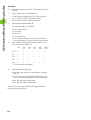
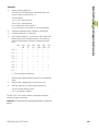
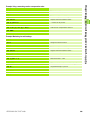
Units of measure
You can program the CNC PILOT either in the metric or inch system.
The units of measurement listed in the table below apply to all inputs
and displays.
Measure
Metric
Inches
Coordinates
mm
inches
Lengths
mm
inches
Angle
degrees
degrees
Shaft speed
rpm
rpm
Cutting speed
m/min
ft/min
Feed per revolution
mm/rev
inch/rev
Feed per minute
mm/min
inch/min
Acceleration
m/s2
ft/s2
42
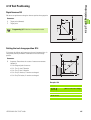
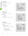
1.5 Tool Dimensions
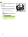
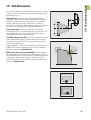
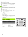
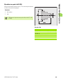
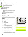
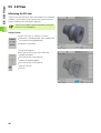
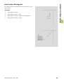
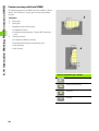
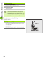
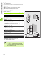
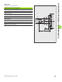
1.5 Tool Dimensions
The CNC PILOT requires information on the specific tools for a variety
of tasks, such as calculating the cutting radius compensation or the
proportioning of cuts.
Tool dimensions:All position values that are programmed and
displayed are referenced to the distance between the tool tip and
workpiece zero point. Since the control only knows the absolute
position of the tool carrier (slide), The CNC PILOT needs the
dimensions XE and ZE to calculate and display the position of the tool
tip, and for Y axis machining, it also needs the dimension in Y.
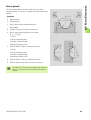
Tool compensation: The tool tip is subjected to wear during
machining processes. To compensate for this wear, the CNC PILOT
uses compensation values. The system automatically adds the
compensation values to the values for length.
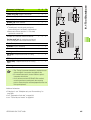
Tool radius compensation (TRC): The tip of a lathe tool has a certain
radius. When machining tapers, chamfers and radii, this results in
inaccuracies which the CNC PILOT compensates with its cutting
radius compensation function.
Programmed paths of traverse are referenced to the theoretical tool
tip S. The TRC function compensates for this error by calculating a
new path of traverse, the equidistant line.
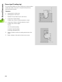
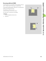
Milling cutter radius compensation (MCRC):In milling operations,
the outside diameter of the milling cutter determines the contour.
When the MCRC function is not active, the system defines the center
of the cutter as the zero point for paths of traverse. The MCRC
function compensates for cutter radius by calculating a new path of
traverse, the equidistant line.
HEIDENHAIN CNC PILOT 4290
43
44
1.5 Tool Dimensions
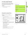
Basics of Operation
HEIDENHAIN CNC PILOT 4290
45
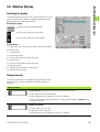
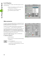
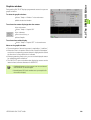
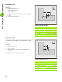
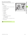
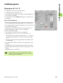
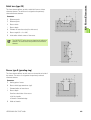
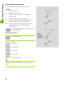
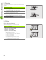
2.1 User Interface
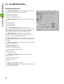
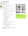
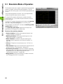
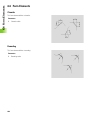
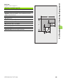
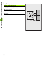
2.1 User Interface
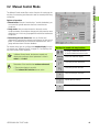
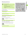
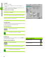
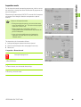
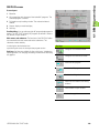
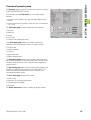
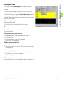
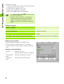
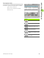
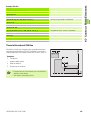
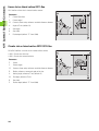
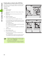
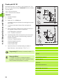
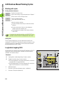
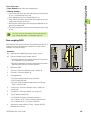
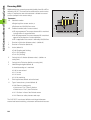
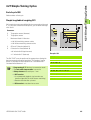
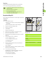
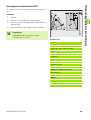
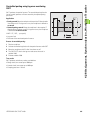
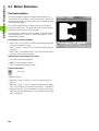
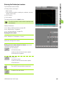
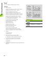
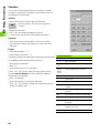
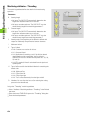
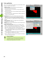
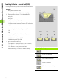
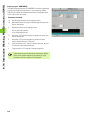
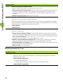
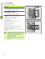
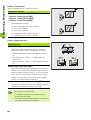
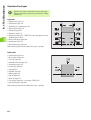
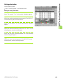
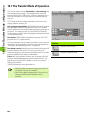
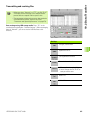
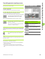
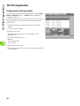
Screen displays
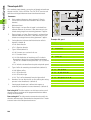
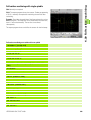
1
Operating mode bar: Shows the status of the operating modes.
The active mode is shown with a dark-gray background.
Programming and organization operating modes:
The selected mode of operation is shown at right next to the
symbol.
Additional information such as the selected program,
submode, etc. are shown below the operating mode
symbol.
2
Menu bar and pull-down menu enable you to select functions.
3
Working window: Size and content depend on the operating
mode.
4
Machine display: Shows the current status of the machine (tool
position, the cycle and spindle situation, active tool, etc.). The
machine display is configurable.
5
Status bar
Simulation, TURN PLUS: Displays the current settings or
information on the next operating steps.
Other operating modes: Displays the most recent error
message
6
Calendar date and service “traffic light”
Date and time
A colored background signalizes an error or a PLC message.
The “traffic light” indicates the maintenance status of the
machine.
7
Soft-key row: Shows the current meaning of the soft keys.
8
Vertical soft-key row: Shows the current meaning of the soft
keys. For more information: see the machine manual.
46
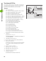
2.1 User Interface
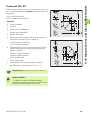
Controls and displays
Operating elements of the CNC PILOT:
Screen with
Horizontal and vertical soft keys: The meaning is shown above or
next to the soft keys.
Auxiliary key 1: Acts as the Esc key
Auxiliary key 2: Acts as the Insert key
Auxiliary keys 3: PLC keys
Keyboard with
Alphabetic keyboard with integrated numeric keypad
Keys for operating mode selection
Touchpad: For cursor positioning (menu or soft key selection,
selection from lists, selecting edit boxes, etc.)
Machine operating panel with
Operating elements for the manual and automatic operation of the
lathe (cycle keys, manual direction keys, etc.)
Handwheel for exact positioning in manual mode
Override button for feed-rate override
Operating information on the touchpad: Normally you use the
touchpad as an alternative to the cursor keys. In the following, the
keys below the touchpad are referred to as the left and right mouse
keys.
The functions and operation of the touchpad are similar to the mouse
operation of the Windows operating systems.
Single click of the left mouse key or tap on the mouse pad:
Positions the cursor in lists or input windows.
Activates menu points, soft keys or buttons.
Double click of the left mouse key or double tap on the mouse pad:
Activates the selected element in lists (activates the input
window).
Single click of the right mouse key:
Same function as the Esc key. Prerequisite: the ESC key is
permitted in this situation (for example to go back by one menu
level).
Same function as the left mouse key when selecting soft keys or
buttons.
HEIDENHAIN CNC PILOT 4290
47
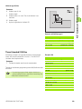
2.1 User Interface
Selecting the operating mode
Keys for operating mode selection
Manual control operating mode
Automatic operating mode
Programming modes
Organization modes
You can usually switch operating mode at any times. In some
situations, you cannot switch operating modes when a dialog box is
open. In this case, close the dialog box before changing operating
modes. After the change, the new mode starts in the function in which
it was last exited.
In the Programming and Organization operating modes, the CNC
PILOT differentiates between the following situations:
No operating mode is selected (no entry next to the operating mode
symbol): Select the desired mode from the menu.
Operating mode selected (indicated next to the operating mode
symbol): The functions of this operating mode are available.
Within the programming or organization modes, you can switch the
modes by soft key or by repeatedly pressing the corresponding
mode key.
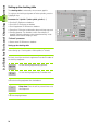
Data input, selection of functions
Data are entered and edited in input windows. An input window
consists of several input fields. You position the cursor with the
touchpad or with the PgUp/PgDn keys to the input box.
Once the cursor is located in the box, you can enter your data or
overwrite existing data. With the right/left arrow keys you can place
the cursor on a position within the input box in order to delete
characters or add data. The “up/down” arrow keys or “Enter” confirm
and terminate the entry.
Some dialogs have more input fields than a window can show. In
these cases, more than one input window appears on the screen, one
superimposed on the other. You will recognize this through the
window number in the top line. To toggle between input windows,
use the PgUp/PgDn keys.
48
2.1 User Interface
When you press the OK button, the control accepts the data entered
or edited. As an alternative you can press the Ins key to confirm the
data, regardless of the cursor position. If you leave the input window
by pressing the “Cancel” button or the ESC key, entries or changes
will be lost.
If the dialog consists of more than one input window, you already
confirm the data when pressing the PgUp/PgDn key.
Note: Instead of selecting the OK or Cancel button, you
can press the Ins or Esc key.
List operations: DIN PLUS programs, tool lists, parameter lists, etc.
are displayed as lists. You can scroll through a list with the touchpad
or arrow keys to check data, to select the position where you wish to
enter data, or to highlight items for operations like deleting, copying,
editing, etc.
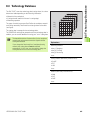
After having selected the desired list position or a list item, press the
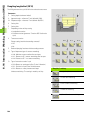
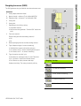
ENTER, INS, ALT or DEL key to execute the operation.
Menu selection: The individual menu items are preceded by the 9field symbol with one field marked. This key represents the key on the
numeric keypad. Press the marked button to select the function.
The function selection begins in the horizontal menu row, then goes
to the pull-down menus. In the pull-down menu you again press the
marked key. As an alternative you can select the menu item with the
touchpad or with the Up/Dn arrow keys and then press ENT.
Soft keys: The meaning of the soft keys is dependent on the current
operating situation. The CNC PILOT indicates the function of the soft
keys with symbols or keywords.
Some soft keys work like “toggle switches.” A function is active when
the associated field in the soft-key row is highlighted in color. The
setting remains in effect until the function is switched off.
Screen buttons: Example of screen buttons are the OK and Cancel
buttons for terminating a dialog box or the buttons contained in the
“Extended inputs” window.
Select the button by cursor and press ENT, or select the button using
the touchpad and press the left mouse button.
HEIDENHAIN CNC PILOT 4290
49
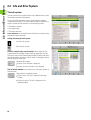
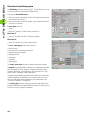
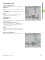
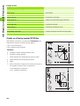
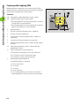
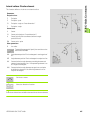
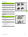
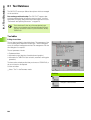
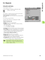
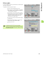
2.2 Info and Error System
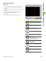
2.2 Info and Error System
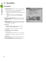
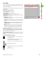
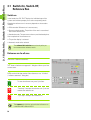
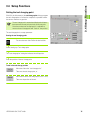
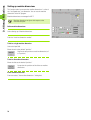
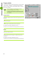
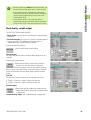
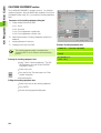
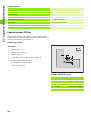
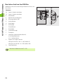
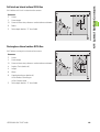
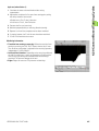
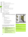
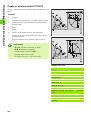
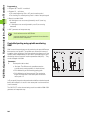
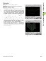
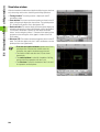
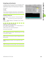
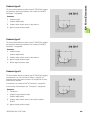
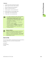
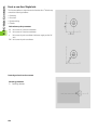
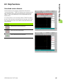
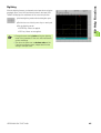
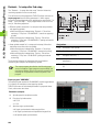
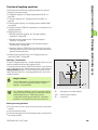
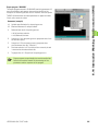
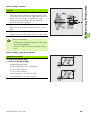
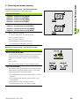
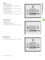
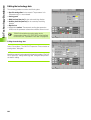
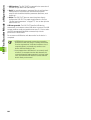
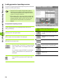
The info system
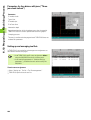
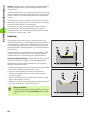
The info system calls excerpts from the User's Manual to the screen.
The header shows the selected topic.
You'll usually find information on the current operating situation
(context-sensitive help). if no context-sensitive help is available for a
specific situation look for the topics in the following sources:
The table of contents
The subject index
The search functions
Cross references are marked in the text. Click the cross references by
touchpad to jump to that topic.
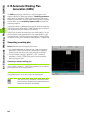
Calling and exiting the info system:
U
Call the info system
U
Exit the info system
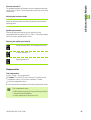
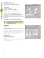
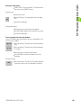
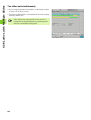
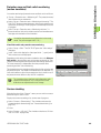
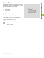
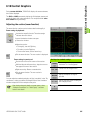
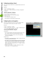
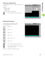
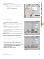
Contents, subject index, search function: When called, the info
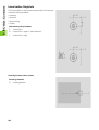
system opens the standard window (figure at upper right). Use the
soft key to switch to the Content/Index window in order to find topics
through the table of contents or subject index, or through the search
function (figure at lower right).
Content/Index window:
Soft key active: Window is displayed.
U
U
Soft key not active: Window is not displayed.
Size of the info window: Use the soft key to switch the window to
maximum size.
Large window or standard window:
Soft key active: The info is displayed in the large
window.
U
U
50
Soft key not active: The info is displayed in the
standard window.
2.2 Info and Error System
Navigating in the info system:
U
You navigate by touchpad as is usual in Windows
programs.
If the topic of information exceeds the window size:
U Navigate with the up/down cursor keys and PgUp/
PgDn keys through the displayed topic. Prerequisite:
The cursor must be located in the topic window and
not in the Content/Index window.
Moving the cursor:
U Press the soft keys. The cursor switches between the
topic window and the Content/Index window.
Next/previous topic:
U
Call the next topic from the table of contents.
U
Call the previous topic from the table of contents.
Next/previous topic: The info system saves the history.
U
Go to the previous topic.
U
Go to the next topic.
OEM help: This soft key is only operable if the machine tool builder
has saved information in the online help.
U
Call the OEM help.
HEIDENHAIN CNC PILOT 4290
51
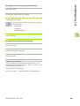
2.2 Info and Error System
Context-sensitive help
You'll usually find information on the current operating situation
(context-sensitive help). if no context-sensitive help is available for a
specific situation look for the topics in the following sources:
The table of contents
The subject index
The search functions
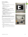
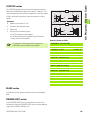
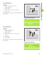
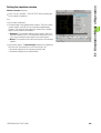
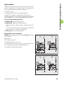
Direct error messages
The CNC PILOT uses a direct error message whenever immediate
error correction is possible. Confirm the message and correct the
error.
Example: The input value of the parameter is out of range.
Information of the error message:
Error description: Explains the error
Error number: For service questions
Time of day: Time when the error occurred (for your information)
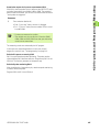
Symbols
Warning: The CNC PILOT indicates the problem. The
program run / operation continues.
Error: The program run/operation is stopped. You must
correct the error before you can continue the current job.
52
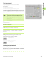
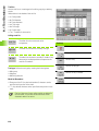
2.2 Info and Error System
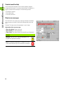
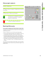
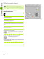
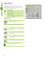
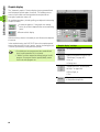
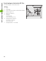
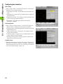
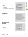
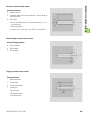
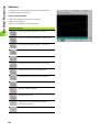
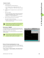
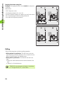
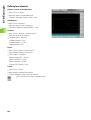
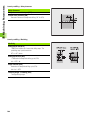
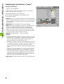
Error display
If during the system start or program run or other operation an error
occurs, it is indicated in the date box, displayed in the status line, and
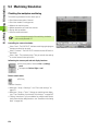
saved in the error display.
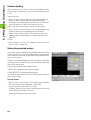
The date and time remain highlighted in red until all of the errors have
been canceled.
Information of the error message:
Error description: Explains the error
Error number: For service questions
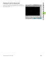
Channel number: Slide for which the error occurred.
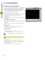
Time of day: Time when the error occurred (for your information)
Error class (only with errors):
Background: This message serves as information, or merely a
“small” error has occurred.
Cancel: The current operation (cycle run, traverse command, etc.)
was cancelled. You can resume operation once the error has been
cleared.
Emergency stop: All traverse and the execution of the DIN
program was stopped. You can resume operation once the error
has been cleared.
Reset: All traverse and the execution of the DIN program was
stopped. Switch off the control for a moment, then restart.
Contact your machine manufacturer if the error occurs again.
System error, internal error: If a system error or internal error
occurs, write down all information on the displayed message and
inform your machine manufacturer. You cannot correct an internal
error. Switch off the control and restart.
Warnings during the simulation: In the event of problems during
simulation of an NC program, the CNC PILOT displays a warning in the
top line.
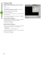
Viewing and deleting error messages:
U
Activate the error display. The error system shows all
accumulated errors.
U
If more than one error is shown, navigate with the
cursor keys within the error display.
U
Deletes the error message marked with the cursor.
U
Deletes all error messages.
U
Display further information on the error marked with
the cursor.
U
Exit the error display.
HEIDENHAIN CNC PILOT 4290
53
2.2 Info and Error System
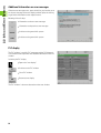
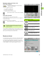
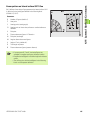
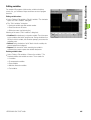
Additional information on error messages
When an error message occurs, press the info key, or place the cursor
on the error message in the error display and then press the info key,
to get further information on the respective error.
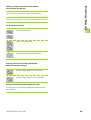
Meaning of the soft keys:
U
Information on the next error message.
U
Information on the previous error message.
U
Switches to the general info system
U
Switches to the general info system
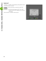
PLC display
The PLC window is used for PLC messages and the PLC diagnosis.
Your machine manual provides more detailed information on the PLC
window.
Activating the PLC display:
U
Opens the “error display”
U
Switches to the PLC window
U
Close PLC window
U
Return to error display
The PLC window is shown as alternative to the error window.
54
2.3 Data Backup
2.3 Data Backup
The CNC PILOT stores NC programs, operating-resource data and
parameters on the hard disk. Since the possibility of damage to the
hard disk due to excessive vibration or shock cannot be eliminated,
HEIDENHAIN recommends making regular backup copies of your
programs, operating resource data and parameters on a PC or on USB
memory media.
You can use DataPilot 4290, the WINDOWS “Explorer” or other
suitable programs for backing up your data on a PC.
For data exchange and data backup, you can use the Ethernet
interface and the USB interface. Data exchange on the basis of the
serial interface (RS-232) is also possible.
HEIDENHAIN CNC PILOT 4290
55
2.4 Explanation of Terms
2.4 Explanation of Terms
MP: With machine parameters (MP) the control is interfaced to the
machine, settings are made, etc.
Cursor: In lists, or during data input, a list item, an input field or a
character is highlighted. This “highlight” is called a cursor.
Cursor keys: You can move the cursor with the arrow keys, PgUp,
PgDn of the touchpad.
Navigating: Within a list or an input box, you can move the cursor
to any position you would like to check, change, delete or add to. In
other words, you "navigate" through the list.
Active/inactive functions, menu items: Functions or soft keys
that at present cannot be selected are shown in gray.
Dialog box: Dialog boxes are also called input windows.
Editing: Editing is changing, deleting and adding to parameters,
commands, etc. within programs, tool data or parameters.
Default value: If the parameters of DIN commands or other
parameters are preassigned values, these values are referred to as
“default values.”
Byte: The capacity of a storage disk is indicated in bytes. Since the
CNC PILOT features a hard disk, the individual program lengths (file
sizes) are expressed in bytes.
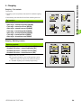
Extension: File names consist of the actual name and the
extension. The name part and the extension part are separated by a
dot “.”. The extension indicates the type of file. Examples:
„*.NC“DIN programs
„*.NCS“DIN subprograms
„*.MAS“Machine parameters
56
Manual Control and
Automatic Modes
HEIDENHAIN CNC PILOT 4290
57
3.1 Switch-On, Switch-Off, Reference Run
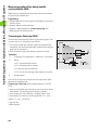
3.1 Switch-On, Switch-Off,
Reference Run
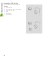
Switch-on
In the header, the CNC PILOT displays the individual steps of the
system start and then prompts you to select an operating mode.
Whether the reference run is necessary depends on the encoders
installed:
EnDat encoder: Reference run is not necessary.
Distance-coded encoders: The position of the axes is ascertained
after a short reference run.
Standard encoder: The axes move to known, machine-based points.
After completion of the reference run:
This position display is activated.
Automatic mode can be selected.
The software limit switches are active only after you
have traversed the reference marks.
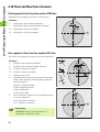
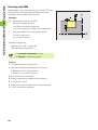
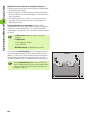
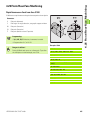
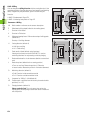
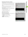
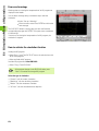
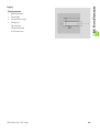
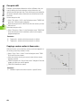
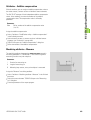
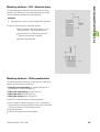
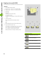
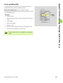
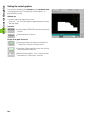
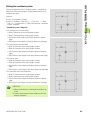
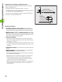
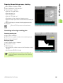
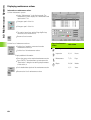
Reference run for all axes
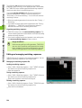
Select Ref > Reference automatic.
The “Status of reference run approach” dialog box informs you of the
current status.
Either set the slides that need to find a reference or set “All slides”
(“reference automatic” dialog box)
To start the reference run, press Cycle Start.
“Feed stop” interrupts the reference run. Cycle start
resumes the reference run.
“Cycle stop” interrupts the reference run.
The sequence in which the axis make their reference run
is defined in MPs 203 and 253 ff.
58
3.1 Switch-On, Switch-Off, Reference Run
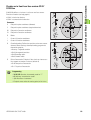
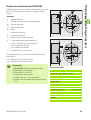
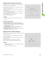
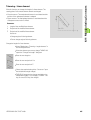
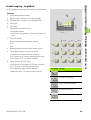
Reference jog for single axis
Select Ref > Reference jog.
The “Status of reference run approach” dialog box informs you of the
current status.
Set slides and axes (“Reference jog” dialog box)
The reference run is conducted for as long as the
Cycle Start key stays pressed. To interrupt the
reference run, release the key.
“Cycle stop” interrupts the reference run.
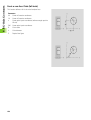
Monitoring EnDat encoders
If your machine is equipped with EnDat encoders, the control saves
the axis positions during switch-off. During switch-on, the CNC PILOT
compares for each axis the position during switch-on with the position
saved during switch-off.
If there is a difference, one of the following messages appears:
“Axis was moved after the machine was switched off.” Check the
current position and confirm it if the axis was in fact moved.
“Saved encoder position of the axis is invalid.” This message is
correct if the control has been switched on for the first time, or if the
encoder or other control components involved were exchanged.
“Parameters were changed. Saved encoder position of the axis is
invalid.” This message is correct if configuration parameters were
changed.
The cause for one of the above listed messages can also be a defect
in the encoder or control. Please contact your machine supplier if the
problem recurs.
HEIDENHAIN CNC PILOT 4290
59
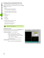
3.1 Switch-On, Switch-Off, Reference Run
Switch-off
“Shutdown” is available in the programming and organization modes
if no operating mode is selected.
U
Press the soft key to switch off the CNC PILOT.
U
Confirm the security query with OK. After a few
seconds, the CNC PILOT requests you to switch off
the machine.
Proper switch-off is recorded in the error log file.
60
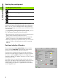
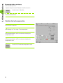
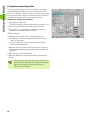
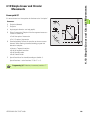
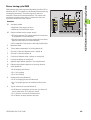
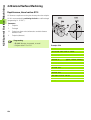
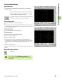
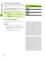
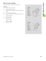
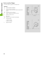
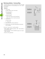
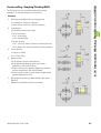
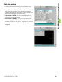
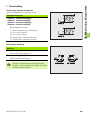
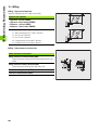
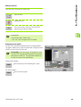
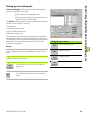
3.2 Manual Control Mode
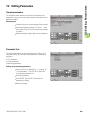
3.2 Manual Control Mode
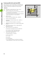
The Manual Control mode offers various functions for setting up the
machine, for measuring tool dimensions and for manually machining
workpieces.
Options of operation:
Manual mode: With the “machine keys” and the handwheel, you
can control the spindle and move the axes to machine the
workpiece.
Setup mode: Here you enter the tools to be used, set the
workpiece datum, the workpiece change point, the protection zone
dimensions etc. In this way you prepare the machine to machine the
workpieces.
Determining the tool dimensions: You can find the tool
dimensions by touching the workpiece with the tool or with a touch
probe. As an alternative you can measure the dimensions with a
gauge and enter them in the tool database.
For manual control you can configure the machine display for up to
six variants (see “Machine Display” on page 97). You adjust by soft
key which variant will be displayed.
In Manual Control mode, the data are entered and
displayed according to control parameter 1 either in
meters or in inches.
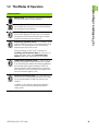
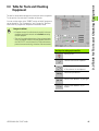
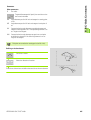
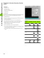
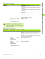
Soft keys for manual and setup functions
Assign a handwheel to an axis
Set the handwheel transmission
Switch the machine display
Turret one position backward
Remember: If the machine has not been referenced:
The position display is not valid.
The software limit switches are not active.
Turret one position forward
Enter the feed per revolution
Spindle speed, entering
Enter the M function
HEIDENHAIN CNC PILOT 4290
61
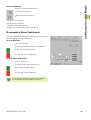
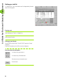
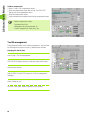
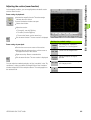
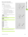
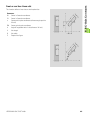
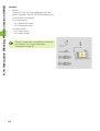
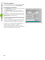
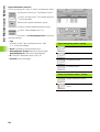
3.2 Manual Control Mode
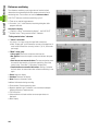
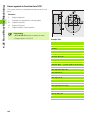
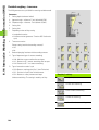
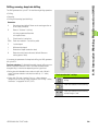
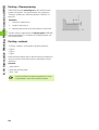
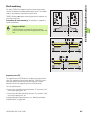
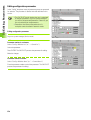
Entering the machine data
Setting the feed rate
In the menu group F you define a feed rate per revolution or per
minute.
Setting the feed per revolution:
U
U
Select F > Feed per revolution
Enter the feed rate in mm/rev (or inches/rev)
Setting the feed rate per minute:
U
U
Select F > Feed per minute
Enter the feed rate in mm/min (or inches/min) and press OK.
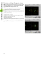
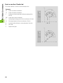
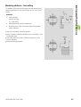
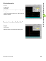
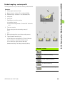
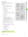
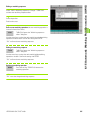
Setting the spindle speed or spindle position
In the menu group S, you define the spindle speed, a constant cutting
speed, or you position the spindle.
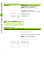
Setting the spindle speed:
U
U
Select S > Spindle speed S
Enter the speed in rpm
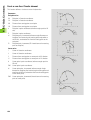
Setting the constant surface speed:
U
U
Select S > V constant.
Enter the cutting speed in m/min (or ft/min) and press OK.
You can enter a constant cutting speed only for slides with
an X axis.
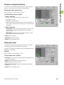
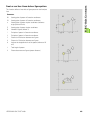
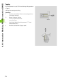
Entering the speed limitation
Available as of software version 625 952-05.
Precondition: Log on as “System manager” (or higher).
U
U
U
To switch to the required spindle, press the spindle change key
Select S > Spindle point stop
Enter the speed in rpm
The current speed limitation for the selected spindle is entered as
proposed value. The speed limitation entered is saved in MP 805, ..
(absolute maximum rpm).
Conduct a spindle point stop (spindle positioning):
U
U
U
To switch to the required spindle, press the spindle change key
Select S > Spindle point stop
Enter the angular position (“spindle point stop” dialog box)
U Cycle Start positions the spindle
U
62
“Cycle stop” exits the dialog box
3.2 Manual Control Mode
Insert the nominal tool
U Select T. Enter the turret position, or
U
the next turret position, or
U
the previous turret position, or
Functions of the tool change:
Move the tool into position
Calculate “new” tool dimensions
Display “new” actual values in the position display
M commands in Manual Control mode
In the menu group M you either type in the M function to be run or you
select the desired function from the menu.
To run an M function:
U
U
Select M > M direct
Enter the M number (“M function” dialog box)
U
Cycle Start runs the M function
U
“Cycle stop” exits the dialog box
To select and run an M function:
U
U
Select “M function”
Using the menu, select the M function
U
Cycle Start runs the M function
U
“Cycle stop” exits the dialog box
The content of the M menu depends on the machine.
Yours may differ from the example shown here.
HEIDENHAIN CNC PILOT 4290
63
3.2 Manual Control Mode
Manual turning operations
The “manual” menu group includes G functions, simple longitudinal
and transverse turning, and manual NC programs written by the
machine tool builder.
Simple longitudinal and transverse turning operations:
U
U
U
Select Manual > Constant feed
Select the direction of feed (“Constant feed” dialog box)
Control the feed rate with the cycle keys
With “constant speed,” a feed rate per revolution must be
defined.
To run a G function:
U
U
U
U
Select Manual > G function
Enter the G number (“G function” dialog box)
Enter the function parameters
Press OK: The G function is executed
The following G functions are permitted:
G30 – Rear-face machining
G710 – Adding tool dimensions
G602..G699 – PLC functions
Manual NC programs
Depending on the configuration of a lathe, the machine manufacturer
can includes NC programs supporting the machinist in manually
operating the lathe (Example: Switching to rear-face machining).
U
U
U
Select “Manual”
Select the desired Manual NC program from the menu
The control loads the NC program and displays it
U Cycle Start activates the NC program
64
3.2 Manual Control Mode
Handwheel
U
Assign the handwheel to a principal axis or C axis
(“Handwheel axes” dialog box
U
Define the feed rate or angle of rotation per
handwheel increment (“Handwheel axes” dialog
box).
U
The cancel the handwheel assignment, press the
“Handwheel” soft key with opened dialog box.
The handwheel assignment and speed ratio are shown in the machine
display (the axis letter and the decimal place of the handwheel
traverse ratio are marked).
The handwheel assignment is canceled by:
Switching the slides
Switching the operating modes
Pressing a manual direction key
Spindle and manual direction keys
The machine operating keys are used for machining under manual
control and for special functions such as finding positions or
compensation values (Teach-in, scratching, etc.).
The tool is activated and the spindle speed and feed rate defined first.
You define the following parameters by MP:
MP 805, 855, ...: Spindle speed during jog
MP 204, MP 254, ...rapid traverse velocity
Spindle keys
Switch the spindle on in M3/M4
direction.
The spindle rotate in M3/M4
direction as long as the key is
pressed (spindle jog)
Spindle STOP
To move the slide diagonally, press the X and Z axis
direction keys simultaneously.
Manual direction keys (jog keys)
Move slide in X direction
Move slide in Z direction
Move slide in Y direction.
To move the slide in rapid
traverse, simultaneously press
the rapid traverse key and the
axis direction key
HEIDENHAIN CNC PILOT 4290
65
3.2 Manual Control Mode
Slide/spindle change key
On lathes with multiple slides the following keys, functions and
displays refer to the selected slide:
Manual direction keys
Setup functions (for example workpiece zero point setting, set tool
change point)
Slide-dependent display elements of the machine display
Display of the “selected slide”: Machine display
The “selected slide” is listed in the “slide display” (see “Machine
Display” on page 97).
To change the slide, press the slide change key
On lathes with multiple spindles the following keys and displays
refer to the selected spindle:
Spindle keys
Spindle dependent display elements of the machine display
The “selected spindle” is listed in the “spindle display” (see
“Machine Display” on page 97).
To change the spindle, press the spindle change key
66
Slide/spindle change key
Switch to the next slide
Switch to the next spindle
3.3 Table for Tools and Chucking Equipment
3.3 Table for Tools and Chucking
Equipment
The tool list (turret table) indicates the current tool carrier assignment.
To set up a tool list, enter the ID numbers of the tools.
You can use the entries in the TURRET section of the NC program to
set up the tool list. The “Compare list” and “Accept list” functions
refer to the NC program last interpreted in automatic mode.
Danger of collision
Compare the tool list with the tools actually in the tool
magazine and check the tool carrier before executing
the part program.
The tool list and the dimensions of the registered tools
must correspond to the tool actually present, because
the CNC PILOT uses this data for all slide movements,
protective zone monitoring, and other slide movements.
Soft keys for setting up the tool list
Deleting a tool
Take the tool from the clipboard
Deleting a tool
Place the tool in the clipboard
Edit the tool parameters
Entries in the database – by tool type
Entries in the database – by ID
number
HEIDENHAIN CNC PILOT 4290
67
3.3 Table for Tools and Chucking Equipment
Setting up a tool list
In “Setup tool list” you can declare the tool list independently from the
data of an NC program.
Entering a tool
Select Setting up > Tool list > Compile list
Select the tool location.
Entering the tool directly:
Press ENTER (or the INS key). The CNC PILOT opens the “Setup”
dialog box
Enter the ID number and click OK to close the dialog box.
Select the tool from the database:
List the tools by type mask, or
List the tools by ID number mask
Place the cursor on the nominal tool.
Insert the tool.
68
3.3 Table for Tools and Chucking Equipment
Deleting a tool
Select Setting up > Tool list > Compile list
Select the tool location.
Use the soft key, or
Press the DEL key to delete the tool
Changing the tool location
Select Setting up > Tool list > Compile list
Select the tool location.
Deletes the tool and saves it in the “ID number
clipboard”
Select a new tool location.
Take the tool from the “ID number clipboard” If the
location was occupied, the previous tool is taken into
the clipboard.
HEIDENHAIN CNC PILOT 4290
69
3.3 Table for Tools and Chucking Equipment
Comparing a tool list with an NC program
The CNC PILOT compares the current tool list with the entries in the
NC program last translated in automatic mode. The entries in the
TURRET section are considered to be nominal tools.
The CNC PILOT shows the following tools marked:
Actual tool not equal to nominal tool
Actual tool not occupied, nominal tool occupied
Tool locations that are not assigned in the NC program cannot be
selected.
Danger of collision
Tool pockets that are occupied but, according to the NC
program, are not needed, are not marked.
The CNC PILOT accounts for a tool entered, even if it
does not correspond to the nominal assignment.
Comparing a tool list
Select Setting up > Tool list > Compare list
The CNC PILOT shows the current contents of the tool list and marks
deviations from the programmed tool list.
Select marked tool pocket
Press the INS key (or ENTER). The CNC PILOT opens
the “nominal-actual comparison” dialog box
Accept the ID number of the “nominal tool” in the
tool list
Look for the tool in the database
Insert the tool.
70
3.3 Table for Tools and Chucking Equipment
Transferring the tool list from an NC program
The CNC PILOT transfers the new tool assignment from the TURRET
section (reference: the NC program last interpreted in Automatic
mode).
Depending on the previous turret assignment, the following might
occur:
Tool not used: The CNC PILOT enters the new tools in the tool list.
Positions that were occupied in the old tool list, but are not used in
the new list, are retained. Delete the tool, if required.
Actual tool location differs from location in tool list: A tool is not
entered when its newly assigned pocket differs from the pocket
specified in the tool list. The CNC PILOT displays a message
indicating this error. Change the tool location.
As long as a tool position differs from the nominal assignment it
remains highlighted.
Danger of collision
Tool locations that are occupied but, according to the
NC program, are not needed, are kept.
The CNC PILOT accounts for a tool entered, even if it
does not correspond to the nominal assignment.
Accepting the tool list
Select Setting up > Tool list > Accept list
Simple tools
The setup functions use tools that are listed in the database. If the NC
program uses “simple tools,” proceed as follows:
U
U
Run an interpretation of the NC program. The CNC PILOT
automatically updates the tool list.
If the positions in the tool list are occupied by “old” tools, the
confirmation request “Update tool list?” appears. The entries are
updated only after you have confirmed the request.
Tools that are not registered in the database are identified by the code
“_AUTO_xx” (xx: T number), and not by an ID number.
Define the parameters of simple tools in the NC program.
HEIDENHAIN CNC PILOT 4290
71
3.3 Table for Tools and Chucking Equipment
Tool life management
The tool life management allows you to define the sequence of
exchange and declare the tool to be ready for use. The tool life/
quantity is defined in the tool database.
Apart from ID numbers and tool type descriptions, the tool list includes
data for tool life management:
Status: Shows the remaining tool life/quantity.
Ready for use: When the tool life has expired/the defined number
of parts has been produced, the tool is “not ready for use” any
longer.
Atw (replacement tool): If a tool is “not ready for use,” a
replacement tool is inserted.
The “Tool life management” dialog box is used for entering and
displaying the tool life data.
You can use the variable programming in your NC program to evaluate
sequential events that you enter in “Event 1” and “Event 2.”
Tool life management parameters:
Repl. tool (replacement tool): T number (turret position) of the
replacement tool
Event 1: Sequential event that is triggered when the life of a tool has
expired/a tool has produced the defined quantity (Event 21..59).
Event 2: Sequential event that is triggered when the tool life/
quantity of parts of the “last tool” has expired/a tool (Event 21..59).
Ready for use: Set the tool to “ready for use” or “not ready for use”
(applies to tool life management only).
The tool life data are evaluation only if the tool life
management is active.
72
3.3 Table for Tools and Chucking Equipment
Entering the tool life parameters
Select Setting up > Tool list > Tool life management
The CNC PILOT displays the entered tools
Select the tool location.
Press ENTER. The CNC PILOT opens the “Tool life management”
dialog box.
Enter the replacement tool and the other tool life parameters.
Press the “New cutting edge” button: The CNC PILOT sets the tool
life/quantity to the value programmed in the database and sets the tool
to ready for use.
Updating the tool life data of all tools
Select Setting up > Tool list > Update tool life management
Confirm the confirmation request with OK; the CNC PILOT sets the
tool life/quantity to the value defined in the database and sets all tools
in the tool carrier to ready for use.
The CNC PILOT displays the “Tool list – Tool life management” for
inspection.
Application example: The cutting edges of all tools used have been
replaced. Part production is to be continued, using the tool life
management function.
HEIDENHAIN CNC PILOT 4290
73
3.3 Table for Tools and Chucking Equipment
Setting up the chucking table
The chucking table is evaluated by the concurrent graphics.
To switch to the chucking assignment of further spindles, press the
PgUp/PgDn keys.
Parameters for “spindle x” (main spindle, spindle 1, ..)
Chucking ID: Reference to database
Chuck jaws ID: Reference to database
Chuck supplement ID: Reference to database
Clamp form: Define the inside/outside clamp and clamp step used
Clamping diameter: The diameter at which the workpiece is
clamped. (Workpiece diameter when clamped externally; inside
diameter when internal clamping is used)
“Tailstock” parameters
Sleeve center ID: Reference to database
Setting up the chucking table
Select Setting up > Chucking table > Main spindle (or Tailstock)
For chuck, chuck jaws and chuck supplement: Enter the ID number of
the chucking equipment.
List the chucking equipment by type mask
List the chucking equipment by ID number mask
Select the chucking equipment from the database
Clamp form: Press the soft key several times to set
the clamp form
Enter the clamping diameter
74
3.4 Setup Functions
3.4 Setup Functions
Setting the tool changing point
With G14, the slide moves to the tool change point. Always program
the tool change point as far from the workpiece as possible to allow
the turret to rotate to any position.
The tool change point is entered and displayed as distance
between machine zero point and tool carrier zero point.
Since these values are not displayed, it is advisable to
move to the tool change point and “teach-in” the position.
The tool change point is a setup parameter.
Setting the tool changing point
For more than one slide: Define the desired slide
Select Setting up > Tool change point
The “tool change point” dialog box indicates the valid position.
Enter the position of the tool change point.
Teach in the tool change position
Move the slide to the “tool change point.”
Take over the tool change point, or
Move the axis to the tool change point (or X or Y axis).
Take over the position of the axis
HEIDENHAIN CNC PILOT 4290
75
3.4 Setup Functions
Shifting the workpiece zero point
The shift is referenced to the machine zero point.
You can move the workpiece zero point for all principal
axes.
The workpiece zero point is a setup parameter.
Specify the workpiece datum
For more than one slide: Define the desired slide
Move the tool into position
Select Setting up > Shift zero point
The “displace zero point” dialog box displays the new workpiece zero
point.
Touch the tool to the face
Contact position = tool zero point
Accept the tool contact position as workpiece zero
point
Workpiece zero point relative to the contact position
Accept the tool contact position
Enter the measured value (distance of the tool contact position from
the workpiece zero point)
Enter the position of the workpiece zero point
76
3.4 Setup Functions
Defining the protection zone
Protection zone parameters:
Serve for protection zone monitoring—not as software
limit switches
Given with respect to the machine zero point
X values are radius dimensions
99999/-99999 means no monitoring of this protection
zone side
The protection zone parameters are managed in the parameters MP
1116, 1156 and following.
Defining the protection zone
Insert any tool (except T0).
Select Setting up > Selection zones
Teach in the protection zone parameters per axis
Select the input field.
Position the tool to the protection zone limit.
Accept the position as “protection zone -X” (or +X, Y, +Y, -Z, +Z)
Teach in positive or negative protection zone parameters
Select any positive or negative input field.
Position the tool to the positive or negative “protection zone.”
Accept all positive or negative axis positions
Enter the protection zone parameters
HEIDENHAIN CNC PILOT 4290
77
3.4 Setup Functions
Setting up machine dimensions
This function takes into account the machine dimensions 1 to 9 and
the “configured axes” per dimension. You can use the machine
dimensions in the NC program.
Machine dimensions are managed in MP 7.
Machine dimensions are given with respect to the
machine zero point.
Define machine dimensions
Select Setting up > Machine dimensions
Enter the “machine dimension number”
Teach in a single machine dimension
Select the input field.
Move the axis to the desired “position.”
Confirm the axis position as machine dimension (or Y
or Z position).
Teach in all machine dimensions
Move the slide to the desired “position.”
Accept the axis positions of the slides as machine
dimensions.
Enter machine dimensions
Enter the values (“Set machine dimension x” dialog box)
78
3.4 Setup Functions
Tool measurement
You specify the type of tool measurement in MP 6:
0: Touch-off
1: Measurement with probes
2: Measurement using optical measuring systems
You move according to the measurement method to a certain position
in the working space that is known to the system. Using that
dimension, the CNC PILOT calculates the setting dimensions of the
tool.
The entries in the “Enter measured value” dialog box
are given with respect to the workpiece zero point.
The existing compensation values of the tool are
deleted.
The CNC PILOT enters the calculated tool dimensions
into the database.
Tool measurement
Move the tool into position
Select Setting up > Tool set-up > Tool measuring.
The “Tool measuring T...” dialog box indicates the current tool
dimensions.
Finding the tool dimensions by touch-off with the tool
Select the input field X; touch-off the diameter.
Load the diameter
Select the input field Z; touch-off the face.
Accept Z position
Tool measurement with a touch probe
Select the X/Z input field
Move the tool tip in X/Z direction to the touch probe. The CNC PILOT
loads the “dimension X/Z.”
HEIDENHAIN CNC PILOT 4290
79
3.4 Setup Functions
Measure tools with an optical gauge
Select the X/Z input field
Align the tool point in the X/Z direction with the cross hairs.
Load the value (or Z position)
Enter the tool dimensions
Calculate the tool compensation
Move the tool into position
Select Setting up > Tool set-up > Tool compensation
Assign the handwheel to the X axis and move the tool by the
compensation value
Assign the handwheel to the Z axis and move the tool by the
compensation value
The CNC PILOT loads the compensation values.
80
Overview of soft keys in Automatic mode
In Automatic mode, the data are entered and displayed
according to control parameter 1 either in meters or in
inches. The setting in the “program head” of the NC
program governs the execution of the NC part program. It
has no influence on operation or display.
Switch to “graphic display”
Switch the machine display
Define block display for more
channels
Display basic blocks (individual paths
of traverse)
Suppress/permit variable output
Set single-block mode
Program stop at M01 (selectable
stop)
Run a start-block search
HEIDENHAIN CNC PILOT 4290
81
3.5 Automatic Mode
3.5 Automatic Mode
3.5 Automatic Mode
Program selection
The CNC PILOT interprets the NC program before it can be activated
with Cycle Start. “#-Variables” are entered during the translation
process. A “restart” prevents a new translation, while a “new start”
forces a new translation.
If the “turret table” of the NC program is not the
currently valid table, there is a warning.
The name of the NC program is retained until you select
another program, even if the lathe was switched off in
the meantime.
Program selection
Select Prog > Program selection The CNC PILOT opens the list of NC
programs.
Select the NC program
The NC program is loaded without previous translation if:
No changes were made to the program or tool list.
The lathe was not switched off since the program was last selected.
Restart
Select Prog > Restart selection
The most recently active NC program is loaded without previous
translation if:
No changes were made to the program or tool list.
The lathe was not switched off since the program was last selected.
82
3.5 Automatic Mode
Start again
Select “Prog > New start”
The NC program is loaded and converted.
(Use for starting an NC program containing # variables.)
From DIN PLUS
Select “Prog > From DIN PLUS”
The NC program selected in DIN PLUS is loaded and converted.
HEIDENHAIN CNC PILOT 4290
83
3.5 Automatic Mode
Finding a start block
In the start block search:
Starting at program start, the CNC PILOT complies with the
technology commands but does not conduct a tool change.
The CNC PILOT allows no positioning.
Danger of collision
If the start block includes a T command, the CNC PILOT
first rotates the turret.
The first traversing instruction is executed from the
current tool position.
Select a suitable start block on all slides before you
press the Accept soft key.
Mid-program startup
Activating a start block search
Position the cursor on the start block. (The soft keys support your
search.)
Enter the N number. The cursor is positioned to the
block number
Enter the T number: The cursor is positioned on the
next T command
Enter the L number: The cursor is positioned to the
next subprogram call
The CNC PILOT begins with the start-block search
Starts with the selected NC block
84
3.5 Automatic Mode
Modifying the program run
Skip level
The NC blocks with skip levels are not executed when the skip level is
active. The “Skip levels” display field marks the (active) skip levels
detected by the “block execution.“
The CNC PILOT accounts for activated/deactivated skip
levels after approx. 10 blocks (reason: block scan during
the execution of NC blocks).
Activating/deactivating a skip level
Select “Process > Skip level.”
Activating a skip level
Enter the “Level no.” and two or more skip levels as a “sequence of
digits.”
“Skip levels” display field
Deactivating a skip level
No entry in “Level no.”
Meaning:
Upper row: Entered skip levels
Lower row: Active skip levels
Production with defined quantity
Select “Process > Quantity”
Enter the quantity
Working with defined quantities:
Counting range: 0..9999
The quantity is counted after every program run.
When an NC program is activated with “Program selection,” the
CNC PILOT resets the counter.
When a program has completed the quantity of parts, you can no
longer start the NC program. To start the program again, press “Restart.”
The Quantity remains stored even after the lathe is switched off.
Quantity=0: No limit. The counter counts up the parts.
Quantity > 0: The CNC PILOT manufactures the defined quantity;
the counter counts down the parts.
HEIDENHAIN CNC PILOT 4290
85
3.5 Automatic Mode
V variables
Working with V variables:
The “V variables” dialog box serves for input and display of
variables.
V variables are defined at the beginning of the NC program. The
meaning is specified in the NC program.
To check or enter a V variable:
Select “Process > V variables”
The CNC PILOT displays the defined variables in the NC program.
Change the variable: Press the Edit button
Single-block mode
In single-block mode, only one NC command (basic block) is executed
at a time. The CNC PILOT then stops the cycle.
Set single-block mode
Activate "Single step" mode.
Cycle Start runs the next NC command
Selectable stop
If the selectable stop is active, the CNC PILOT stops with M01 and
goes into the feed stop condition.
Program run with selectable stop
Activate selectable stop
The CNC PILOT goes with an M01 into the feed stop condition.
Cycle start resumes the program run
86
Status of selectable stop
Selectable stop off
Selectable stop on
3.5 Automatic Mode
Feed rate override F%
The programmed feed rate changes with the programmed feed rate
(range of 0 % to 150 %). The machine display shows the current feed
rate override.
Adjusting the feed rate override
Adjust the desired override with the override knob (in the machine
operating panel)
Spindle speed override
With the spindle speed override you can deviate from the
programmed feed rate (range of 50 % to 150 %). The machine display
shows the current spindle speed override.
Adjusting the spindle speed override
Spindle speed at 100% (of the programmed value)
Increase speed by 5%
Reduce speed by 5%
Compensation
Tool compensation
U Select “Comp > Tool compensation”
U T number: The CNC PILOT shows the active T number and the
compensation values. You can enter a different T number.
U Enter the compensation values.
U Values entered here are added to the existing compensation values.
Tool compensation values:
Effective beginning with the next positioning command
Transferred into the database
Can be changed by no more than 1 mm
HEIDENHAIN CNC PILOT 4290
87
3.5 Automatic Mode
Additive compensation
U Select “Comp > Tool compensation values”
U Enter the compensation values (901 to 916). The CNC PILOT
displays the valid compensation values.
U Enter the compensation values.
U Values entered here are added to the existing compensation values.
Additive compensation values:
Activated with G149
Managed in the set-up parameter 10
Can be changed by no more than 1 mm
Tool life management
During Automatic mode, in the “tool life management,” switch off and
on the ready-for-use status of a tool, or update the tool life data.
Changing the tool life data
Select Comp > Tool life management.
The CNC PILOT displays the tool list with the current tool life data.
Select the tool location.
Press ENTER. The CNC PILOT opens the “Tool life management”
dialog box.
Select “Ready for use”
Press the “new cutter” button to update the tool life data.
88
3.5 Automatic Mode
Inspection mode
For the inspection mode, interrupt the program run, check or correct
the active tool, or change the cutter. Resume the NC program at the
point of interruption.
When the tool is retracted, the CNC PILOT stores the first five traverse
movements. Each change in direction corresponds to a path of
traverse.
Notes on the inspection mode:
During the inspection process you can turn the turret,
press the spindle keys, etc. The return motion program
inserts the “correct” tool.
When changing the cutting edge, select the
compensation values so that the tool stops before the
point of interruption.
In the cycle stop condition you can interrupt the
inspection cycle with the ESC key and switch to
“Manual control.”
The inspection cycle is executed as follows:
1
2
3
Interrupt the program sequence and retract the tool.
Check the tool and replace the cutting edge if necessary.
Retract tool
1. Inspection – Retract the tool
Interrupt the program run
„Select INSPection
To retract the tool, use the manual direction keys.
If necessary, swivel the turret.
HEIDENHAIN CNC PILOT 4290
89
3.5 Automatic Mode
2. Inspection – Check the cutting edge
Inspect the tool; if necessary, replace it.
Conclude the inspection process. The CNC PILOT
loads the return motion program (_SERVICE).
The “Tool compensation” dialog box appears. Enter the tool
compensation.
If you are using a new cutting edge, modify the tool compensation so
that the tool—when returning—comes to a stop before the point of
interruption.
If necessary, activate the spindle.
3. Inspection – Return the tool to the work
At the beginning of the returning program, the control asks the two
questions “Scrambled takeoff on restart?” and “Start from/before
interruption point.” Your answers determine the return motion
program as follows:
Scramble takeoff = yes (see 3.1 Return the tool and “scrambled
takeoff”)
Move to point of interruption: The return motion program
positions the tool at rapid traverse to the interruption point and
continues the program without stopping.
Move to before point of interruption: The return motion program
positions the tool in rapid traverse to a position before the
interruption point and continues the program without stopping.
Scramble takeoff = no (see 3.2 Return the tool and stop)
Move to point of interruption: The return motion program
positions the tool to the interruption point and stops the program.
Move to before point of interruption: The return motion program
moves the tool to a position before the interruption point and
stops the program.
“Scrambled takeoff = yes” is usually used when the cutting edge is
not exchanged.
90
3.5 Automatic Mode
3.1 Return the tool and “scrambled takeoff”
Start the return motion program.
The “Scrambled takeoff on restart?” dialog box appears. Enter 1
(=yes)
Takeoff from IP:
The “Start from point of interruption (IP)” dialog box appears. Enter 0
(= to IP)
The return motion program positions the tool from/before the
interruption point and continues the program without stopping.
Takeoff before IP:
The “Start from point of interruption (IP)” dialog box appears. Enter 1
(=before IP)
Then, in the “Distance from the interruption point” dialog box, enter
the distance from the point of interruption
The return motion program positions the tool before the interruption
point and continues the program without stopping.
The inspection cycle has been completed.
HEIDENHAIN CNC PILOT 4290
91
3.5 Automatic Mode
3.2 Return the tool and stop
Start the return motion program.
The “Scrambled takeoff on restart?” dialog box appears. Enter 0 (=no)
Takeoff from IP:
The “Start from point of interruption (IP)” dialog box appears. Enter 0
(=from IP)
The return motion program positions the tool on/before the
interruption point and stops.
Takeoff before IP:
The “Start from point of interruption (IP)” dialog box appears. Enter 1
(=before IP)
Then, in the “Distance from the interruption point” dialog box, enter
the distance from the point of interruption
The return motion program positions the tool before the interruption
point and stops.
Resume the program run. The inspection cycle has
been completed.
Select “Insp(ection)” again
The “Scratch with tool” dialog box opens (for information)
Assign the handwheel to the X/Z axis and “scratch” the workpiece.
Press “Accept value” to save the compensation values defined per
handwheel.
Resume the program run. The inspection cycle has
been completed.
92
3.5 Automatic Mode
If the NC program stops before the interruption point, the
“Distance from the interruption point” comes into play:
If the entered distance is greater than the distance
between the start of the NC block and the interruption
point, program sequence begins at the start of the
interrupted NC block.
If the entered distance is less than the distance
between the start of the NC block and the interruption
point, the CNC PILOT takes the distance into account.
Block display, variable output
The CNC PILOT differentiates between:
Block display: Lists the NC blocks according to the programmed
sequence.
Basic block display: The cycles are “resolved.” Individual paths of
traverse are shown. The numbering of the basic blocks is
independent of the programmed block numbers.
Activate the basic block display:
U
Switch on/off the basic block display
Channel display
For lathes with several slides, activate the block display for up to 3
channels.
Switching the channel display:
U
Each time the soft key is pressed it connects a
channel. Then only one channel is displayed.
If the block display is active for one channel, the basic
block is shown in the right window. If the block display is active for
two or more channels, the basic block display replaces the block
display.
Font size
The font size of the block display can be adjusted in the menu.
U
U
“Display > Font size > Smaller” reduces the font size
“Display > Font size > Larger” increases the font size
Variable output
U
Pressing the soft key enables the variable soft key
output (with PRINTA). Otherwise the variable output
is suppressed.
Load monitoring display: see “Load Monitoring” on page 100
HEIDENHAIN CNC PILOT 4290
93
3.5 Automatic Mode
Graphic display
The “Automatic graphics” function displays the programmed blank
and finished part and the paths of traverse. This enables process
control of non-visible areas during production and provides an
oversight of production status, etc.
All machining operations, including milling, are depicted in the turning
window (XZ view).
U
Activate the graphics. If the graphic was already
active, the screen is adapted to the current machining
status.
U
Return to block display
With the soft keys shown in the table you can influence the depiction
of traverse.
In the standard setting, the CNC PILOT draws the complete path of
traverse after every block. In the “motion” setting, the cutting process
is shown synchronously to the production process.
“Graphic display” soft keys
Set single-block mode
If no blank part was programmed, the standard blank
form (control parameter 23) is assumed.
“Motion” must be stopped at the beginning of the NC
program. For program section repeats (M99), motion
start in the next program run.
Display of the paths of traverse (see
“Path display” on page 367):
Line, or
Cutting trace
Tool depiction (see “Screen layout,
soft keys” on page 363):
Point of light, or
Tool
Displaying the cutting synchronously
to the production process
94
3.5 Automatic Mode
Enlargement, reduction, and selecting a section
Zoom settings by keyboard:
U
Activate the magnify function The red rectangle
indicates the new section.
U Adjust the section:
To magnify, use the PgDn key
To reduce, use the PgUp key
To move the frame, use the arrow keys
U
Exit the zoom function. The new section is displayed
Zoom settings by touchpad:
U
U
U
Position the cursor to one corner of the section
While holding the left mouse key, pull the cursor to the opposite
corner of the section
Right mouse key: Return to standard size
U Exit the zoom function. The new section is displayed.
“Graphic display” soft keys
Last setting was “workpiece
maximum” or “working space”
Cancels the last magnification
After having enlarged a detail to a great extent, select
“Workpiece maximum” or “Work space,” and then
isolate a new detail.
You can make the standard setting by soft key (see table). The “By
coordinates” setting (simulation window and position of the tool zero
point) is given with respect to the selected slides.
Depicts workpiece in the largest
possible magnification
Depicts the work space including the
tool change position
Set simulation window and position
of the workpiece zero point
Mechatronic tailstock
A moveable opposing spindle can be used as a mechatronic tailstock
if the machine tool builder prepares the machine for this function.
If so, start the sleeve mode with the “Manual PLC” menu item. A
prerequisite is that the Automatic mode was stopped with cycle stop
or that an M0/M01 in the NC program triggered a cycle stop.
HEIDENHAIN CNC PILOT 4290
95
3.5 Automatic Mode
Post-process measuring status
Post-process measuring means that the workpiece is measured
outside the lathe and that the results are transferred to the CNC
PILOT. The “PPM Info” dialog box contains information on the status
of the measured values, displays the transferred results, and allows
initialization of communication with the measuring device.
Operation of “post-process measuring”:
U
U
U
Select Display > PPM Status
The PPM Info dialog box provides information on the status of the
measured values and the most recently transferred results.
If you select “Init,” the post-process measuring function is reinitialized and all measured values are deleted.
PPM Info dialog box:
Measured-value coupling (same as control parameter 10)
Off: Measuring results are immediately transferred. Previous
values are overwritten.
On: Measuring results are not transferred until the previous
results have been processed.
Measured values valid: Status of the measured values (after the
measured values have been transferred with G915, the status “No”
is displayed).
#939: Total result of last measurement
#940..956: Measuring results last transferred by the measuring
function
The post-process measuring function saves the measured
values received in the clipboard. The PPM Info dialog box
displays in #939..956 the values contained in the
clipboard—not the variables.
96
3.6 Machine Display
3.6 Machine Display
Switching the display
The machine display of the CNC PILOT can be configured. Per slide,
you can configure up to 6 displays in Manual mode and Automatic
mode (starting with control parameter 301).
Switching the display
U
Switch to the next configured display.
U
Switch to the display of the next slide.
U
Switch to the display of the next spindle.
Position display
In “Display type” (MP 17) you set the values of the position display:
0: Actual values
1: Following error
2: Distance of traverse
3: Tool tip with respect to machine zero point
4: Slide position
5: Distance from reference dog to zero pulse
6: Nominal position
7: Difference from tool point to slide position
8: Nominal director position
Display elements
The following table explains the standard display fields. For further
display fields: see “Control parameters for machine display” on
page 580
Display elements
Position display (distance between tool tip and workpiece zero point)
Empty field: Axis has not been homed
Letter designating the axis appears in white: Axis disabled
Display values shown in gray (only with X or Z): The actual value display is invalid because
the B axis was tilted.
Display of C position
“Index”: marks the C axis “0/1”
Empty box: C axis is not active
Letter designating the axis appears in white: Axis disabled
HEIDENHAIN CNC PILOT 4290
97
3.6 Machine Display
Display elements
Distance-to-go display (distance remaining in the current traverse command)
Bar graphic: Distance remaining in millimeters
Field below left: Actual position
Field below right: Distance to go
T display without tool life monitoring
T number of active tool
Tool compensation values
T display with tool life monitoring
T number of active tool
Tool life data
Quantity of workpieces/time per workpiece
Number of finished workpieces in this batch
Production time or current workpiece
Total production time for this batch
Load display
Load of the spindle motors/axis drives with regard to rated torque
D display (additive compensation)
Number of the active compensation
Compensation values
Slide display
Cycle status:
Cycle on
Feed stop
Cycle off
Manual control
Inspection cycle
Set-up mode
98
Symbol appears in white: Disabled
Numeral: Selected slide
White background: No “converting and mirroring” active (G30)
Color background: “Converting and mirroring” active (G30)
Cycle status
Bar graphic: Feed rate override in %
Upper field: Feed rate override
Lower field:
Current feed rate
With stationary slide: Nominal feed rate (gray text)
Slide number on a blue background means the rear face is active
3.6 Machine Display
Display elements
Spindle display
Spindle status:
Direction of spindle
rotation M3
Direction of spindle
rotation M4
Spindle stop
Symbol appears in white: Disabled
Numeral in spindle symbol: Gear range
“H”/Numeral: Selected spindle
Spindle status
Bar graphic: Feed rate override in %
Upper field: Spindle speed override
Lower field:
Current speed
With stationary spindle: Nominal speed (gray text)
With position control(M19): Spindle position
Spindle in position
control (M19)
C axis is “activated”
Overview of enabled elements
Shows the enabling status of up to 6 NC channels, 4 spindles, and 2 C-axes. Enabled
elements are marked (green).
Display group at left: Enabled
F: Feed rate
D: Data
S: Spindle
C: C axis
1..6: Number of the slide/spindle of the C axis
Display group in center: Status
Zy – left dash: Cycle on/off
Zy – right dash: Feed Stop
R=Reference run
A: Automatic mode
H: Manual control
F: Retracting (after crossing the limit switches)
I: Inspection mode
E: Set-up switch
Display group at right: Spindle
Display for direction of rotation left/right
Both active: Spindle positioning (M19)
HEIDENHAIN CNC PILOT 4290
99
3.7 Load Monitoring
3.7 Load Monitoring
The load monitoring function of the CNC PILOT compares the current
torque, or the values for the work of the drives, with the values from
a reference run.
If “torque limit 1” or the “work limit” is exceeded, the CNC PILOT
marks the tool as worn out. If torque limit 2 is exceeded, the CNC
PILOT assumes tool breakage and stops the machining process (feed
stop). Violations of limit values are reported as error messages.
The load monitoring identifies worn tool in the “tool diagnosis bits.” If
you are using the tool life monitoring function, the CNC PILOT will
manage the replacement of tools. As an alternative, you can evaluate
the tool diagnosis bits in the NC program.
The load monitoring function defines the monitoring zones and the
drives to be monitored (G995) in the NC program. The torque limits of
a monitoring zone depend on the maximum torque determined by the
reference machining cycle.
The CNC PILOT checks the values for torque and work in each
interpolator cycle and displays the values in a time reference grid of
20 ms. The limit values are calculated from the reference values and
the limit factor (control parameter 8). You can later change the limit
values in “Edit load parameters.”
Make sure that the conditions for reference machining
comply with those for production (feed-rate/speed
override, tool quality, etc.).
The CNC PILOT monitors up to four components per
monitoring zone.
Using “G996 Type of load monitoring,” you can control
the hiding the rapid traverses paths and the monitoring
of torque and/or work.
The graphic and numeric displays are relative to the
rated torque values.
100
3.7 Load Monitoring
Machining using load monitoring
During use of the load monitor, a worn tool should require significantly
more torque than a sharp one. As a rule, drives that are subjected to
considerable loads should be monitored. That usually means the
spindle.
Due to the relatively small torque variations, it is difficult to monitor
machining operations with small cutting depths.
A decrease in torque cannot be identified.
Defining the monitoring zones: The reference values for torque
depend on the maximum torque values of the zone. Therefore, lower
torque values cannot always be monitored.
Facing with constant cutting speed: The spindle is monitored as
long as the acceleration is <= 15 % of the mean value from maximum
acceleration and maximum braking deceleration (MP 811, ...). Since
acceleration increases as a result of the increase in rotational speed,
the CNC PILOT usually only monitors the period after the first cut.
Empirical values for the machining of steel:
For longitudinal turning the cutting depth should be > 1 mm.
For recessing the cutting depth should be > 1 mm.
For hole drilling, ensure that the diameter drilled is between 6 and
10 mm.
HEIDENHAIN CNC PILOT 4290
101
3.7 Load Monitoring
Reference machining
The reference machining cycle (registration of nominal values)
determines the maximum permissible torque and work of each
monitoring zone. These values are used as reference values!
CNC PILOT executes a reference machining cycle if:
There are no monitoring parameters
You select “yes” in the reference machining dialog box (after
program selection).
Activate the display:
U
„Disp(lay) > select “load monitoring display”: the CNC PILOT
switches to the “Taking nominal values” submenu
“Taking nominal values” submenu:
“Curves” menu item
In curves 1 to 4 you assign the input field to the drives.
With “Display grid” you influence the accuracy of the depiction. A
small value increases the accuracy (values: 4, 9, 19, 39 seconds
per image).
“Mode” menu group
Line graphic: Shows the torque over the time axis.
Bar graphic: Shows the torque as a bar and indicates the peak
values.
Save/do not save measured values: The measured values must
be saved for later analysis of reference machining. Check the
setting in the “Save data” (“Write data”) display field.
Overwrite/do not overwrite limit values: Setting of whether
the limit values are overwritten when reference machining is run
again.
Pause: Stops the display
Continue: Resumes the display
Auto: Return to Automatic menu
Additional information during recording:
Zone number: Present monitoring zone
Negative algebraic sign: Production is not monitored (example:
skipping the paths of rapid traverse).
Tool: Active tool
Selected drives are listed and the current torque values are
displayed.
Block display
102
3.7 Load Monitoring
Production using load monitoring
If you wish to use the load monitoring function for your machining
processes, you must activate it in the NC program (G996).
Display torque values and limit values:
U
Select Disp(lay) > Load monitoring > Display
“Load monitoring > Display” submenu:
“Curves” menu item
In curves 1 to 4 you assign the input field to the drives.
Line graphic: A curve
Bar graphic: Up to four bars
With “Display grid” you influence the accuracy of the depiction. A
small value increases the accuracy (values: 4, 9, 19, 39 seconds
per image).
“Mode” menu group
Line graphic: Shows the torque over the time axis and the limit
values. Limit values gray: Nonmonitored area (hiding rapid
traverse paths).
Bar graphics: Displays the current torque, the values for work
and all limit values of the monitoring zone.
Pause: Stops the display
Continue: Resumes the display
Auto: Return to Automatic menu
Editing limit values
The function for editing the load parameters allows you to analyze
reference machining cycles and optimize limit values.
The CNC PILOT displays the program name of the loaded monitoring
parameters in the header.
Selection:
U
Select Disp(lay) > Load monitoring > Edit
“Load parameter editor” submenu:
Act. load (Load current file) menu item: Monitoring parameters of
the active NC program.
Load: Monitoring parameters you have selected.
Edit: Display and edit the limit values.
Delete reference values: Delete the load parameters of the NC
program.
Auto: Return to Automatic menu
HEIDENHAIN CNC PILOT 4290
103
3.7 Load Monitoring
Editing the load parameters
The “Display and adjust load parameters” dialog box displays the
parameters of one component of one monitoring zone, which can
then be edited.
The bar graphic shows all components of the monitoring zone (the
larger bar displays the values for performance; the smaller bar displays
the values for work). The selected component is highlighted.
Enter the monitoring zone and select the component. The CNC PILOT
displays the reference values. The limit values for performance and
work, which are displayed, can be edited. The tool (T number) is
displayed for information.
Buttons of the dialog box:
Saving: Save the limit values of the component in the specified
zone.
End (or ESC key): Exit the dialog box.
File: Switch to “Line graphics.”
Precondition: The values measured during the reference machining
cycle have been stored.
Analyzing reference machining
The load monitor shows the torque and the limit values of the selected
component over time.
Limit values gray: Nonmonitored area (hiding rapid traverse paths).
In addition the CNC PILOT displays the values of the cursor position
numerically.
Selection:
U
Selection: File button in the “Display and adjust load parameters”
dialog box.
U Switch back to “Edit load parameters”
104
3.7 Load Monitoring
“Analyzer (file display)” submenu:
Set cursor: Position the cursor with the left/right arrow keys or to
the
Beginning of file
Next beginning zone
Maximum in zone
Display menu item: Select the component from the “Display file”
dialog box.
Setting - Zoom: Set the zoom factor. (Small values increase the
accuracy of the display and reduce the step size of the cursor.)
The settings defined for the grid, the time reference grid of the
measured value registration and the cursor position are shown in
the line below the graphic display relative to the start of reference
machining. Time 0:00.00 sec = Start of reference machining cycle.
Load monitoring parameters
Machine parameters for load monitoring (spindle: MP 809, 859, ...;
C axis: MP 1010, 1060; linear axes: MP 1110, 1160, ...):
Start-up time for monitoring [0..1000 ms] is evaluated if “Omit
paths of rapid traverse” is active:
Spindles: A limit value is calculated from the acceleration and
brake ramps. As long as nominal acceleration exceeds the limit
value, the monitoring function is deactivated. As soon as nominal
acceleration falls below the limit value, the monitoring function is
delayed by the start-up time for monitoring.
Linear and C axes: After rapid traverse has changed to feed rate,
the monitoring function is delayed by the “start-up time for
monitoring.”
Number of sample values to be averaged [1..50]
The mean value reduces the sensitivity to short-term peak load
during monitoring.
Maximum torque of drive [Nmm]
Delay in reaction P1, P2 [0..1000 ms]: The CNC PILOT indicates
that torque limit 1/2 has been exceeded after the time “P1/P2” has
passed.
HEIDENHAIN CNC PILOT 4290
105
3.7 Load Monitoring
Control parameter 8 “Load monitoring settings”
Factor for torque limit value 1, 2
Factor for work limit value
Limit value = reference value * factor for limit value
Minimum torque [% of rated torque]: Reference values below
this value are raised to this minimum torque value. This prevents
that limit values are exceeded as a result of minor torque
differences.
Maximum file size [KB]: If the data during measured value
registration exceed the maximum file size, the “oldest” values are
overwritten. Approximate value: 12 KB for one component per
minute of program-run time.
Control parameter 15 “bit codes for load monitoring”:
Assigns the bits number used in G995 to the drives (logical axes).
106
DIN Programming
HEIDENHAIN CNC PILOT 4290
107
4.1 DIN Programming
4.1 DIN Programming
Introduction
The CNC PILOT supports both conventional DIN programming and
DIN PLUS programming.
Conventional DIN/ISO programming: You program the basic
contour with line segments, circular arcs and simple turning cycles.
For conventional DIN programming, the simple tool description is
sufficient.
“DIN PLUS” (ISO) programming: The geometrical description of
the workpiece and the machining process are separated. You first
program the geometry of the blank and finished part. Then you
machine the workpiece, using contour-related turning cycles. The
contour follow-up function can be activated for each machining
step, including individual paths of traverse and simple turning
cycles. The CNC PILOT optimizes the machining process as well as
the paths for approach and departure (no noncutting passes).
Example: Structured DIN PLUS program
PROGRAMMKOPF [PROGRAM HEAD]
#MATERIAL [MATERIAL] St 60-2
#EINSPANNDURCHM
120 [CLAMP. DIAM.]
#AUSSPANNLAENGE
106 [CLAMP. LENGTH]
#SPANNDRUCK 20 [CLAMP. PRESSURE]
#SCHLITTEN
#SYNCHRO
REVOLVER 1 [TURRET]
Depending on the type and complexity of your machining task, you can
use either simple DIN programming or DIN PLUS programming.
T1 ID"342-300.1"
NC program sections: The CNC PILOT supports the division of the
NC program into individual program sections.
. . .
Program head (organizational data and setup information)
Tool list (turret table)
Chucking equipment table
Workpiece-blank definition
Description of machined part
Machining of workpiece
Parallel operation: While you are editing and testing programs, your
machine can execute another NC program.
$1 [SLIDE]
T2
ID"111-80-080.1"
SPANNMITTEL [CHUCKING EQUIPMENT] (Zero
point shift Z282)
H1 ID"KH250"
H2 ID"KBA250-77" Q4.
ROHTEIL [BLANK]
N1 G20 X120 Z120 K2
FERTIGTEIL [FINISHED PART]
N2 G0 X60 Z-115
N3 G1 Z-105
. . .
BEARBEITUNG [MACHINING]
N22 G59 Z282
N23 G65 H1 X0 Z-152
N24 G65 H2 X120 Z-118
N25 G14 Q0
[Predrilling 30 mm outside centric face]
N26 T1
N27 G97 S1061 G95 F0.25 M4
. . .
ENDE [END]
108
0
4.1 DIN Programming
DIN PLUS screen
Screen layout:
1
2
3
4
5
Menu bar
NC program bar with the name of the loaded NC programs. The
selected program is marked.
Full, double or triple editing window. The selected window is
marked.
Contour display or machine display
Soft keys
Parallel editing: You can edit up to eight NC program/subprograms in
parallel. The CNC PILOT displays NC programs as desired in either a
full, double, or triple window.
Main menus and submenus: The functions of the DIN PLUS editor
are contained in the main menu and various submenus. The
submenus can be called by
selecting the desired menu item
positioning the cursor in the respective program section
Soft keys: Soft keys are available for fast switching to “neighboring
operating modes” for changing the editing window and for activating
the graphics.
Soft keys
Change to the simulation mode
Change to the TURN PLUS mode
Switch the NC program
Switch the NC program
Switch the editing window
Select full-size window (one editing
window)
Select double or triple window
Activate the graphics
HEIDENHAIN CNC PILOT 4290
109
4.1 DIN Programming
Linear and rotary axes
Principal axes: Coordinates of the X, Y and Z axes refer to the
workpiece zero point.
Remember about negative X coordinates
Not allowed with contour descriptions
Not allowed for turning cycles
The contour follow-up is switched off
The direction of rotation for circular arcs (G2/G3, G12/
G13) has to be set manually
The position of the tool radius compensation (G41/G42)
has to be set manually
C axis as reference axis:
Angle data are with given respect to the zero point of the C axis.
C-axis contours and C-axis operations:
Positions on the front/rear face are entered in Cartesian
coordinates (XK, YK), or polar coordinates (X, C)
Positions on the lateral surface are entered in polar coordinates (Z,
C). Instead of C, the linear value CY is used (“unrolled” reference
diameter).
B
B
B axis—tilted working plane: The B axis makes it possible to drill,
bore and mill in oblique planes. The coordinate system is tilted for
programming in such a way that you can define the drilling patterns
and milling contours in the YZ plane. Machining is then conducted in
the tilted plane.
Secondary axes (auxiliary axes): In addition to the principal axes, the
CNC PILOT supports:
U:Linear axis in X direction
V:Linear axis in Y direction
W:Linear axis in Z direction
A:Rotary axis that rotates about X
B:Rotary axis that rotates about Y
C:Rotary axis that rotates about Z
The auxiliary axes are only programmed in the MACHINING section,
using the functions G0 to G3, G12, G13, G30, G62 and G701. A circular
interpolation is only possible in the principal axes. Rotary axes
(auxiliary axes) are programmed in the MACHINING section, using
G15.
The DIN editor respects only address letters of the
configured axes.
The behavior of the rotary axes B and C depends on
whether they have been configured as principal or
auxiliary axes.
110
Y
B
U
X
A
V
C
W
Z
4.1 DIN Programming
Units of measurement
You write NC programs in metric or inch values. The unit of measure
is defined in the “Unit” box (see “PROGRAM HEAD section” on
page 136).
Once the unit of measure has been defined, it cannot be
edited any longer.
Elements of a DIN program
A DIN program consists of the following elements:
Program number
Program section codes
NC blocks
Commands for program structuring
Comment blocks
The program number begins with “%” followed by up to 8
characters (numbers, uppercase letters or underscore; no diacritical
marks) and the extension “nc” for main programs or “ncs” for
subprograms. The first character must be a number or a letter.
Program section codes: When you create a new DIN program,
certain program section codes are already entered. You can add new
codes or delete existing ones, depending on your program
requirements. A DIN program must contain at least the MACHINING
and END section codes.
NC blocks begin with an N followed by a block number (with up to
four digits). The block numbers do not affect the sequence in which
the program blocks are executed. They are only intended for
identifying the individual NC blocks.
The NC blocks of the PROGRAM HEAD, TURRET and CHUCKING
EQUIPMENT sections are not included in the block number
organization of the DIN editor.
An NC block contains NC commands such as positioning, switching
or organizational commands. Traversing and switching commands
begin with G or M followed by a number (G1, G2, G81, M3, M30, ...)
and the address parameters. Organizational commands consist of key
words (WHILE, RETURN, etc.), or of a combination of letters/
numbers.
You can also program NC blocks containing only variable calculations.
You can program several NC commands in one NC block, provided
they have different address letters and do not have opposing
functions.
HEIDENHAIN CNC PILOT 4290
111
4.1 DIN Programming
Examples:
Permissible combination: N10 G1 X100 Z2 M8
Non-permissible combination:
N10 G1 X100 Z2 G2 X100 Z2 R30 (same address letters are used
more than once) or
N10 M3 M4—opposing functionality
NC address parameters
The address parameters consist of 1 or 2 letters followed by
A value
A mathematical expression
A question mark (VGP simplified geometry programming)
A letter “i” to designate incremental address parameters
(examples: Xi..., Ci..., XKi..., YKi..., etc.)
A # variable (calculated during NC program interpretation)
A V variable (calculated at run time)
Examples:
X20(Absolute dimension)
Zi–35.675(Incremental dimension)
X?(Simplified geometry programming)
X#12(Variable programming)
X{V12+1}(Variable programming)
X(37+2)*SIN(30)(Mathematical expression)
Program branches and repeats
You can use program jumps, repeats and subprograms to structure
a program. Example: Machining the beginning/end of a bar etc.
Skip level: Influences the execution of individual NC blocks
Slide code: You can assign the NC blocks to a specific slide
provided that your lathe is equipped with more than one slide.
Input and output: With “input” the machine operator can influence
the flow of the NC program. Using “output,” you can communicate
with the machinist. Example: The machinist is required to check
measuring points and update compensation values.
Comments are enclosed in brackets “[...].” They are located at the
end of an NC block or in a separate NC block.
112
4.2 Programming Notes
4.2 Programming Notes
Configuring the DIN editor
The following properties of the DIN editor can be configured in the
main menu:
Display/do not display a help graphic next to the dialog box
Number of editing windows
Font size
You save and load these settings.
Help graphic:
U
U
Select Config > Help graphic. The editor opens the “Configuration
of help graphic” dialog box.
Set whether the help graphic should be displayed.
Number of editing windows:
U
Select Config > Window > Full-size window (or > Double window,
> Triple window). The editor sets the selected number of windows.
Font size:
U
U
Select Config > Font size > Less than (or > Greater than). The editor
reduces/enlarges the font size.
Select Config > Font size > Adjust fonts The editor uses the font
size of the selected window for all editing windows.
Saving/loading editor settings:
U
U
U
U
Select Config > Settings > Save. The editor saves the editor
settings.
Select Config > Settings > Load. The editor loads the saved editor
settings including the NC program.
Select Config > Settings > Auto-save on. The editor saves the
condition during switch-off.
Select Config > Settings > Auto-save off. The editor condition is not
saved during switch-off.
HEIDENHAIN CNC PILOT 4290
113
4.2 Programming Notes
Parallel editing
The CNC PILOT runs up to eight NC program/subprograms in parallel
and provides up to three editing windows.
Editing window: Set full-size or multiple windows:
U
Set full-size window
U
Set multiple windows (whether two or three windows
is set in the configuration)
Switch the editing window:
U
Press the soft key, or
U
use the touchpad to click the desired window
Change the NC program:
U
Press the soft key
U
Press the soft key, or
U
use the touchpad to click the NC program in the NC
program bar.
Selecting submenus, positioning the cursor
The submenus can be called by
U
selecting the desired menu item
U
positioning the cursor in the respective program
section
U
Press the ESC key to return to the main menu.
When you call the menu items Geometry,Processing, “Turret
assignment” or “Chucking equipment,” the CNC PILOT jumps to the
corresponding program section.
When you position the cursor in the BLANK, FINISHED PART or
MACHINING section, the CNC PILOT switches to the corresponding
submenu.
Position the cursor:
114
U
“Prog > Prog(ram) start” positions to the beginning of
the program
U
“Prog > Prog(ram) end” positions to the end of the
program
U
With the cursor keys or PgUp or PgDn
4.2 Programming Notes
Making, editing and deleting NC blocks
Make NC block:
The insertion of new NC blocks varies depending on the program
section.
Program head
U
Close the “Editing program head” dialog box: The
CNC PILOT automatically creates the blocks of the
program head (code “#”).
TURRET and CHUCKING EQUIPMENT program sections:
U
Press the INS key: The CNC PILOT opens the dialog
for a new tool or chuck.
U
The new block is inserted after the dialog is finished.
Contour programming, programming the machining process and
programming in subprograms:
U
Press the INS key: The CNC PILOT makes a new block
below the cursor position.
U
Alternatively you can program the NC command
directly. The CNC PILOT makes a new NC block or
inserts the NC command in the existing NC block.
Delete the NC block:
U
Position the cursor on the NC block to be deleted.
U
Press the DEL key: The CNC PILOT deletes the NC
block.
Add an NC element:
U
Position the cursor on an element of the NC block (NC
block number, G or M command, address parameter,
etc.).
U
Insert NC element (G, M, T function, etc.).
HEIDENHAIN CNC PILOT 4290
115
4.2 Programming Notes
Change NC element:
U
Position the cursor on an element of the NC block (NC
block number, G or M command, address parameter,
etc.) or the section code.
U
Press ENTER or double-click with the left mouse key.
The CNC PILOT activates a dialog box which displays
the block number, the number of the G or M function,
or the address parameters of the function, which can
then be edited.
When editing section codes, you can change the associated
parameters (Example: number of the turret). When you edit NC words
(G, M, T), the CNC PILOT activates a dialog box for editing the address
parameters.
Delete NC elements:
U
Position the cursor on an element of the NC block (NC
block number, G or M command, address parameter,
etc.) or the section code.
U
Press the DEL key. The element highlighted by the
cursor and all the related elements are deleted.
(Example: If the cursor is located on a G command,
the address parameters are also deleted.)
Before deleting a complete NC block, the CNC PILOT
displays a confirmation request. Individual elements of an
NC block including G or M functions are deleted by the
editor without confirmation prompt.
Search functions
The search function of the DIN editor supports:
Block no. search:
U
Select “Block > Search functions> Search block” in the main menu.
The editor opens the “Block no. search” dialog box.
U Enter the block number and close the dialog block: The CNC PILOT
positions the cursor on the block number (if it exists).
NC word search (G command, address parameter, etc.):
U
U
U
Select “Block > Search functions> Search word” in the main menu.
The editor opens the “Word search” dialog box.
As of software version 625 952-02: Press <CTRL+F>. The editor
opens the “Word search” dialog box. To continue searching, press
<F>.
Enter the NC word and close the dialog box. The cursor skips to the
first NC block containing the word. The CNC PILOT searches from
the cursor position to the end of the program, then continues
searching from the start of the program.
116
4.2 Programming Notes
Conversational or free editing
In free editing you select the NC functions from the menus and edit
the address parameters in dialog boxes.
In free editing you enter all elements of the NC block. The maximum
block length for “free editing,” is 128 characters per line.
To select “free” editing:
U
U
Select “Block > New: Free input” in the main menu. The DIN editor
inserts an NC block at the cursor position and waits for the entry of
a complete NC block.
Select “Block > Change: Free input” in the main menu. The DIN
editor presents the NC block at the cursor position for editing.
Geometry and machining commands
The G commands are divided into:
Geometry commands for describing the blank and finished part.
Machining commands for the MACHINING section.
Some G functions are used for blank/finished-part
definition and in the MACHINING section. When copying
or shifting NC blocks, keep in mind that “geometry”
functions are used exclusively for describing a contour,
while “machining” functions are used only in the
MACHINING section.
HEIDENHAIN CNC PILOT 4290
117
4.2 Programming Notes
Contour programming
The “contour follow-up” function and contour-related turning cycles
require the previous description of the blank and finished part. For
milling and drilling, contour definition is a precondition if you wish to
use fixed cycles.
Contours for turning
Describe a continuous contour.
The direction of the contour description is independent of the
direction of machining.
CNC PILOT closes open contours paraxially.
Contour descriptions must not extend beyond the turning center.
The contour of the finished part must lie within the contour of the
blank part.
When machining bars, define only the required section as blank.
Contour definitions apply to the entire NC program, even if the
workpiece is rechucked for machining the rear face.
In the fixed cycles, the defined contour is used to program
“reference values.”
To describe blank parts, use
G20 “Blank part macro” for standard parts (cylinder, hollow
cylinder).
G21 “Cast-part macro” for blank-part contours based on finishedpart contours.
Individual contour elements (such as are used for finished-part
contours) where use of G20 or G21 is not possible.
To describe finished parts, use individual contour elements. The
contour elements or the complete contour can be assigned attributes
accounted for during the machining of the workpiece (example:
roughness, oversizes, etc.).
For intermediate machining steps, define auxiliary contours.
Auxiliary contours are programmed in the same way as finished-part
descriptions. One contour description is possible per AUXILIARY
CONTOUR. You can make multiple AUXILIARY CONTOURS.
Contours for C-axis machining:
Contours for C-axis machining are programmed within the
FINISHED PART section.
Identify the contours as a FRONT or SURFACE. You can use section
codes more than once or program multiple contours within one
section code.
Multiple contours in an NC program
The CNC PILOT supports up to four contours (workpiece blank and
finished part) per NC program. The CONTOUR section code
introduces the description. Parameters on zero point shift and the
coordinate system define the position of the contour in the working
space. A G99 in the machining section assigns the machining to a
contour.
118
4.2 Programming Notes
Contour Follow-Up
The CNC PILOT takes the blank part as a basis and accounts for each
cut and each cycle when regenerating the contour. Thus you can
inspect the current contour of the workpiece during each machining
stage. With the “contour follow-up” function, the CNC PILOT
optimizes the paths for approach and departure and avoids noncutting
passes.
Contour regeneration is available only for turning operations. It also
works with auxiliary contours.
Preconditions for contour follow-up:
Workpiece-blank definition
Proper description of tools (“simple definition of tools” is not
sufficient)
Block references
When editing G commands related to the contour (MACHINING
section), activate the contour simulation and load the block references
from the displayed contour.
U
Place the cursor in the input box.
U
Switch to the contour display
U
Place the cursor on the desired contour element
U
Press ENTER to load the block number of this contour
element
Contour generation during simulation
You can save contours generated in the simulation and transfer them
into the NC program. Example: You describe the blank form and
finished part and simulate machining of the first setup. Then you save
the contour. You define a shift of the workpiece zero point and/or a
mirror image. The simulation saves the “generated contour” as the
workpiece blank and the originally defined finished part contour, taking
the zero point shift and mirroring into account.
Download the contours generated for the blank and finished part:
U
U
Position the cursor.
Select “Block > Insert contour” in the main menu.
HEIDENHAIN CNC PILOT 4290
119
4.2 Programming Notes
List of G functions
If you do not know the G number, the DIN editor supports you with
the G function list.
U
Select G in the geometry or machining menu. The
editor opens the G number list.
U
Place the cursor on the desired G function.
U
Press ENTER to load the G number.
Address parameters
Coordinates can be programmed absolutely or incrementally. If you do
not make any entry for X, Y, Z, XK, YK, C, the coordinates of the block
previously executed will be retained (modal).
The CNC PILOT calculates missing coordinates in the principal axes X,
Y or Z if you program “?” (simplified geometry programming).
The machining functions G0, G1, G2, G3, G12 and G13 are modal. This
means that the CNC PILOT uses the previous G command if the
address parameters X, Y, Z, I or K in the following block have been
programmed without a G function However, the address parameters
must have been programmed as absolute values.
The CNC PILOT supports the use of variables and mathematical
expressions as address parameters.
To edit address parameters:
U
Call the dialog box.
U
Position the cursor in the input field and enter/change
the values, or
U
„Call “extended input”
„?“ programming (simplified programming)
Switch from incremental to absolute, or vice versa
Activate variable input
120
4.2 Programming Notes
Tool programming
The designations of the tool pockets are fixed by the machine tool
builder. Each tool holder has a unique T number.
In the T command (MACHINING section) you program the tool holder,
and therefore the position to which the tool carrier rotates. The CNC
PILOT retrieves the assignment of the tools to the tilted position from
the TURRET section, or the tool list (in case the T number is not
defined in TURRET).
Multipoint tools: A multipoint tool is a tool with more than one
cutting edge. During T call, the T number is followed by an S to identify
the cutting edge.
T number.S (S=0 to 4)
S=0 identifies the main cutting edge, which does not need to be
programmed. In the TURRET section, you define only the main cutting
edge.
When a cutting edge of a multipoint tool has become dull, the tool life
management function marks all cutting edges as worn-out.
Examples:
T3 or T3.0: Tilted position 3; main cutting edge
T12.2: Tilted position 12; cutting edge 2
Replacement tools: If you use the tool life monitoring, you define a
sequence of exchange. As soon as a tool is worn out, the CNC PILOT
inserts a replacement tool. The CNC PILOT does not stop the program
run until the last tool of the tool sequence of exchange is worn out.
In the TURRET section and the T commands, you program the first
tool to be changed. The CNC PILOT automatically inserts the
replacement tool. When programming variables (access to tool
compensation or tool diagnosis bits), you also address the first tool of
the sequence. The CNC PILOT automatically addresses the active
tool.
You can define replacement tools in “Setup.”
HEIDENHAIN CNC PILOT 4290
121
4.2 Programming Notes
Subprograms, expert programs
Subprograms are used to program the contour or the machining
process.
In the subprograms, transfer parameters are available as variables.
You can fix the designation of the transfer parameter (see
“SUBPROGRAM section” on page 145).
In every subprogram, the variables #256 to #285 are available for
internal calculations.
Subprograms can be nested up to six times. Nesting means that a
subprogram calls a further subprogram, etc.
If a subprogram is to be run repeatedly, enter the number of times the
subprogram is to be repeated in the Q parameter.
The CNC PILOT distinguishes between local and external
subprograms.
Local subprograms are in the file of the NC main program. Local
subprograms can only be called in from their corresponding main
programs.
External subprograms are stored in separate NC files and can be
called in from any NC main program or other NC subprograms.
Expert programs
An expert program is a subprogram that executes complex processes
and is adapted to the machine configurations (for example, workpiece
transfer to opposing spindles). Expert programs are usually provided
by the machine tool builder.
NC program conversion
For variable programming and user communication, keep in mind that
the CNC PILOT interprets the complete NC program before the
program run.
The CNC PILOT differentiates between:
# variables that are calculated during the conversion of the NC
program
V variables are calculated at run time, which means during the
execution of an NC block.
Inputs/outputs during NC program conversion
Inputs/outputs during NC program run
122
4.2 Programming Notes
Fixed cycles
HEIDENHAIN recommends programming a fixed cycle as follows:
Tool change
Define the cutting data
Position the tool in front of the working area
Definition of safety clearance
Cycle call
Retract the tool
Move to tool change position
Danger of collision!
Remember when omitting cycle programming steps
during optimization:
A special feed rate remains in effect until the next feed
command (for example the finishing feed rate during
recessing cycles).
Some cycles traverse diagonally back to the starting
point if you use the standard programming (for example
roughing cycles).
Typical structure of a fixed cycle
. . .
BEARBEITUNG [MACHINING]
N.. G59 Z..
Zero point shift
N.. G26 S..
Define the speed limit
N.. G14 Q..
Move to tool change position
. . .
N.. T..
Insert the tool
N.. G96 S.. G95 F.. M4
Define the technology data
N.. G0 X.. Z..
Pre-position
N.. G47 P..
Definition of safety clearance
N.. G810 NS.. NE..
Cycle call
N.. G0 X.. Z..
If necessary, retract
N.. G14 Q0
Move to tool change position
. . .
HEIDENHAIN CNC PILOT 4290
123
4.3 The DIN PLUS Editor
4.3 The DIN PLUS Editor
Overview of main menu
The “Prog” pull-down menu (program management) contains the
following functions for NC main and subprograms:
Load existing NC programs
Create new NC programs
Save new or edited NC programs
The “Head” menu group (NC program header) contains functions for
editing
the program header
the turret assignment
the chucking table
With the “Geo” menu item (geometry) you can branch to
programming the workpiece blank or finished part contour. You select
either a workpiece blank or position the cursor to the BLANK or
FINISHED PART section and switch to the geometry menu.
The “Mach” menu item (machining) calls the submenu for
programming the machining. At the same time the CNC PILOT
positions the cursor to the MACHINING section.
The “Pab” menu item (program section code) calls a selection box
with section codes. It enables you to insert additional codes into your
NC program.
The “Block” menu group contains functions for marking and editing
groups of NC program blocks.
The NC Bl menu group contains
Functions for cursor positioning
Functions for numbering the NC blocks
Search functions
“Free editing” function
In the “Config” menu group configuration you can make the
following settings:
Switch-off/on the help graphic
Window configuration
Font size
In addition you can manage the settings”
In the “Graph” menu group you set the graphic window and activate/
deactivate the contour display.
124
4.3 The DIN PLUS Editor
Overview of geometry menu
The Geometry submenu contains G functions and instructions for the
BLANK and FINISHED PART sections.
With the menu items G, Line and Cir you select basic contour
elements:
If you know the G number, call G and enter the number of the G
function.
If you do not know the G number, select the “Line” or the desired
“Cir” (circle)
The Form menu group contains the following form elements:
Recesses
Undercuts
Thread
Centric hole
It also provides subprogram calling
In the Attr. menu group (attribute) you define the following
attributes, which are assigned to contours or contour sections:
Precision stop
Surface roughness
Oversizes
Special feed rates
Additive compensation
The Front menu group contains figures, patterns and elements for
defining milling contours for the front and rear faces. This menu item
cannot be selected until the cursor is placed in the corresponding
program section.
The Surf. menu group (lateral surface) contains figures, patterns and
elements for defining milling contours for the lateral surface. This
menu item cannot be selected until the cursor is placed in the
corresponding program section.
The Instr. menu group (instructions) contains
Section codes
Instructions for structuring the program
Programming with variables
Comments
The Graph. menu item activates or updates the graphic window.
HEIDENHAIN CNC PILOT 4290
125
4.3 The DIN PLUS Editor
Overview of machining menu
The Machining submenu contains G, M, T, S and F functions as well
as further instructions for the MACHINING section.
Selecting the G and M functions:
If you know the G or M number, call the G or M menu and then enter
the number of the function.
If you do not know the G or M number, select the desired function
from the G or M menu.
T menu items (tool call):
U
U
Select T
Enter the T number, or select the tool from the list
Menu item F:
U
Select F. The editor calls G95—Feed per revolution.
Menu item S:
U
Select S. The editor calls G96—Cutting speed
The Instr. menu group (instructions) contains
Section codes
Instructions for structuring the program
Programming with variables
Subprogram calls
Comments
Templates
Working plan
The Graph. menu item activates or updates the graphic window.
A template is a predefined NC code block that is adapted to your lathe
and is integrated in the NC program. Templates generally contain
structure commands, synchronizations, zero point shifts etc. They
make it easier to program complex operations.
Templates are provided by the machine tool builder. He can inform you
whether templates are available on your machine and if so, which
ones. You can optimize the templates for your requirements (see
“DIN PLUS Templates” on page 354).
The working plan function collects all comments that begin with //
and places them before the MACHINING instruction. This gives you an
overview of the NC program’s operations.
126
NC programs contain instructions and information that are configured
specially to your lathe and organization. You can combine these data
in a starting template and use it to write new programs (see
programming example). Such a sample program makes it easier to
write a new program and aids in standardizing NC programs.
If you do not use the starting template, CNC PILOT makes a new NC
program with the standard program section codes.
The degree of detail included in the starting template depends on the
complexity of your machine, your organization and many other criteria.
For more on creating and editing your starting template: see “DIN
PLUS Templates” on page 354.
Example: “Starting template”
PROGRAMMKOPF [PROGRAM HEAD]
#MATERIAL
St 60-2 [MATERIAL]
#MASCHINE [MACHINE]
STANDARD
#SPANNDRUCK [CLAMP. PRESS.]
#SCHLITTEN
40
$1 [SLIDE]
#SYNCHRO
0
REVOLVER 1 [TURRET]
To create a new NC program using a starting template:
U
U
U
U
Select “Prog > New”.
Enter a program name.
Make the settings of the NC main program.
Press “OK.” The CNC PILOT makes an NC program on the basis of
the starting template (prerequisite: The DINSTART.bev file is in the
NCPS directory)
SPANNMITTEL [CHUCKING EQUIPMENT] (Zero
point shift Z...)
H1 ID"KH250"
H2 ID"KBA250-69" X 100 Q2
To create a new NC program:
ROHTEIL [WORKPIECE BLANK]
U
N1 G20 X100 Z100 K2
U
U
U
Select “Prog > New”
Enter a program name
Make the settings of the NC main program
Press the Program Head button: The NC editor creates the NC
program and switches to the program head editing function.
To create a new subprogram:
U
U
U
U
Select “Prog > New”
Enter a program name
Make the subprogram settings
Press “OK.” The NC editor creates the subprogram.
FERTIGTEIL [FINISHED PART]
N2 G0 X0 Z0
BEARBEITUNG [MACHINING]
N22 G59 Z100 [enter zero point shift]
N23 G26 S4000 [enter speed limit]
N24 G65 H1 X0 Z-100 [enter chuck position]
N25 G65 H2 X100 Z-100
N26 G14 Q0
ENDE [END]
HEIDENHAIN CNC PILOT 4290
127
4.3 The DIN PLUS Editor
New NC program
4.3 The DIN PLUS Editor
NC program management
Loading the NC program:
Load NC program in the next free window:
U
Select Prog > Load > Main program (or > Subprogram). The CNC
PILOT displays the files.
U Select and load the NC program or subprogram
Load NC program in selected window:
U
U
U
Select and activate free editing window
Select Prog > Load > Main program (or > Subprogram). The CNC
PILOT displays the files.
Select and load the NC program or subprogram
Saving the NC program:
To conclude the NC program editing:
U
Select Prog > Close. If the NC program is new or changed, the CNC
PILOT opens the Save NC Program dialog box
U Set whether and under what name the NC program is to be saved
Save the NC program of the active window:
U
Select Prog > Save. The CNC PILOT saves the NC program but
stays in the editing window.
Save the NC program of the active window under a new program
name:
U
Select Prog > Save As. The CNC PILOT opens the Save NC Program
dialog box.
U Enter the file name and set whether the editing window should be
closed
Save the NC programs of all active windows:
U
Select Prog > Save All. The CNC PILOT saves all NC programs but
they stay in the editing window.
When you exit the DIN PLUS operating mode, the NC
programs are saved automatically. The old version of
the NC program is overwritten.
If an NC program was changed but not saved, the
program name is shown in red. If the NC programs were
not changed or saved, the program name is shown in
black.
128
4.3 The DIN PLUS Editor
Graphics window
During editing CNC PILOT displays programmed contours in up to two
graphic windows.
To select the graphic windows:
U
Select “Graph. > Window” in the main menu
U
Mark the desired window
To activate the contour display/update the contour:
In the main menu:
Select “Graph. > Graphic ON”
U
In the submenu:
Press the soft key, or
U
U
Select Graphic
To activate the machine display:
U
Select “Graph. > Graphic OFF” in the main menu
Notes on the graphic window:
The starting point of the turning contour is marked by a “small box.”
When the cursor is located on a block of the “blank or finished part”
section the corresponding contour element is highlighted in red and
the direction of contour definition is indicated.
When programming fixed cycles, you can use the displayed contour
for establishing block references.
The CNC PILOT starts at the base when displaying contours on the
lateral surface (reference diameter for SURFACE).
Additions/changes on the contours are not considered
until GRAPHIC is selected again.
Unambiguous NC block numbers are a prerequisite for
the contour display!
HEIDENHAIN CNC PILOT 4290
129
4.3 The DIN PLUS Editor
Workpiece-blank programming
To describe the workpiece blank, proceed as follows:
Standard blank (cylinder, hollow cylinder):
U
U
Select “Geo > Blank> Chuck piece/bar G20” in the main menu.
The CNC PILOT
Creates an NC block in the BLANK section
Switches to the “Geometry” submenu
Activates the “Chuck part, cylinder/tube G20” dialog box
Casting as blank (the workpiece blank contour is based on the finished
part contour):
U
U
Select “Geo > Blank> Casting G21” in the main menu.
The CNC PILOT
Creates an NC block in the BLANK section
Switches to the “Geometry” submenu
Activates the “Casting G21” dialog box
Any workpiece blank contour:
U
U
U
Select “Geo > Blank> Free contour” in the main menu.
The CNC PILOT
Positioning the cursor on the BLANK program section
Switches to the “Geometry” submenu
Define through individual contour elements (like a finished part
contour)
Block numbering
Setting the block numbering: The block numbering settings are the
starting block number and the block-number increment. The first NC
block receives the starting block number and the block-number
increment is added for each further NC block. The settings for starting
block number and block number increment are tied with the NC
program. Call:
U
U
Select “Block > Increment” in the main menu. The editor opens the
“Config. of block no. increment” dialog box.
Enter the starting block number and block number increment.
Renumbering the NC blocks: The editor
renumbers the NC blocks.
corrects the block references of contour-related G commands in the
main program and all subprograms called in this main program.
corrects the block references for subprogram calls.
renumbers the NC blocks of a subprogram if this subprogram is
used by the main program and is open in the editor.
Call:
U
Select “Block > Block numbering” in the main menu. The editor
renumbers the NC blocks.
130
4.3 The DIN PLUS Editor
Programming instructions
Instructions of the geometry menu
Below are the contents of the Instr. (instructions) menu group
DIN PLUS words:
U
U
Select “Instr. > DIN PLUS words.” The editor opens the selection
box.
Select the desired instruction for program structuring or the input/
output command.
Variable:
U
U
Select “Instr. > Variables.” The editor opens the input line.
Enter a variable or mathematical expression.
Program section codes:
Auxiliary contour:
U
Select “Instr. > AUXILIARY CONTOUR.” The editor enters the code
in an appropriate position.
Front face, rear face or lateral surface contour:
U
U
Select „Instr.> FRONT FACE“ (or „.. > LATERAL SURFACE“, „.. >
REAR FACE“)“. The editor opens the dialog for position input.
Enter the position of the plane.
Comment:
U
U
Select “Instr. > Comment line.” The editor opens the input line.
Enter text. The comment is inserted above the position of the
cursor.
Instructions of the machining menu
Below are the contents of the Instr. (instructions) menu group
HEIDENHAIN CNC PILOT 4290
131
4.3 The DIN PLUS Editor
DIN PLUS words:
U
U
Select “Instr. > DIN PLUS words.” The editor opens the selection
box.
Select the desired section code, instruction for program structuring
or the input/output command.
Variable:
U
U
Select “Instr. > Variables.” The editor opens the input line.
Enter a variable or mathematical expression.
Skip level:
U
U
Select “Instr. > / Deletion.” The editor opens the “Skip level” dialog
box.
Enter skip level [1 to 9].
Slide code:
U
U
Select “Instr. > $ Slide.” The editor opens the “Slide number”
dialog box.
Enter the slide number. Enter several slides as a sequence of
numbers.
External subprogram call:
U
Select “Instr. > L call external.” The editor opens the selection list
with the available subprograms.
U Select the desired subprogram and enter the transfer parameter.
Internal subprogram call:
U
U
Select “Instr. > L call internal.” The editor opens the “subprogram
call” dialog box.
Enter the subprogram name (block number with which the
subprogram begins) and the transfer parameters.
Comment:
U
U
Select “Instr. > Comment line.” The editor opens the input line.
Enter text. The comment is inserted above the position of the
cursor.
Templates:
U
Select “Instr. > Template selection > Template selection ...”
The editor opens the dialog box of the template
After the dialog box is closed the template is taken into the NC
program
Creating and NC program overview:
U
U
Select “Instr. > Working plan.”
The editor
collects all comments that begin with “// ...”
places these comments in the MACHINING section
132
4.3 The DIN PLUS Editor
Block group menu
This function enables NC block groups (several successive NC
blocks) to be moved, copied, deleted or exchanged between NC
programs.
To define an NC block group, highlight the first and last line of the
block group. Then select the desired operation on the block group.
In order to exchange blocks groups between NC programs, copy the
block group to the clipboard. Then read in the block group from the
clipboard. A block group remains in the clipboard until it is overwritten
by another block group.
Marking a block group:
Beginning of block group:
U
Position the cursor on the beginning of a block group.
Press “Start mark”
Block group end:
U
U
U
Position the cursor on the “end of a block.”
Press “End mark”
Saving a block group in the clipboard:
Load the marked block group in the clipboard and delete it:
U Select “Edit >Cut.”
Copy the marked block group into the clipboard:
U
Select “Edit > Copy to clipboard”
Get block group from clipboard:
U
U
Position the cursor at the target position.
Select “Edit > Paste from clipboard” The block group is inserted at
the target position.
Deleting a block group:
U
Select “Edit >Delete.” The editor deletes the marked block group
definitively (it is not stored in the clipboard).
Moving a block group:
U
U
Position the cursor at the target position.
Select “Edit >Displace.” The marked block group is moved from its
initial position to the position indicated by the cursor.
HEIDENHAIN CNC PILOT 4290
133
4.3 The DIN PLUS Editor
Copying a block group:
U
U
Position the cursor at the target position.
Select “Edit > Copy and paste.” The block is inserted at/copied to
the target position.
The “Cancel” menu item:
U
Select “Cancel.” The editor removes all marking.
The “Insert contour” menu item
U
Select “Insert contour.” The editor inserts the most recent
workpiece blank and finished part contour in the simulation below
the cursor position
As an alternative of the block group menu, you can use the usual
WINDOWS key combinations for marking, deleting, shifting etc.:
U
U
U
U
U
Marking by moving the cursor keys while holding the shift key.
Ctrl + C: Copy the marked text to the clipboard
Shift + Del(ete): Delete the marked text and save it in the clipboard
Ctrl + V: Insert text from the clipboard at the cursor position
Del(ete): Delete the marked text
134
4.4 Program Section Code
4.4 Program Section Code
A new DIN program is already provided with section codes. You can
add new codes or delete existing ones, depending on your program
requirements. A DIN program must contain at least the MACHINING
and END section codes.
You can select further program section codes under the menu item
“PAb” (Program section code) in the main menu, in the “Instr.” menu
or in the DIN PLUS Words selection box. The CNC PILOT inserts the
section code at the correct position.
For more than one independent contour definition for
drilling/milling, use the program section codes (FRONT
END, REAR END, etc.) each time.
Example: Program section codes
. . . [Sections of the contour
description]
ROHTEIL [WORKPIECE BLANK]
N1 G20 X100 Z220 K1
FERTIGTEIL [FINISHED PART]
N2 G0 X60 Z0
N3 G1 Z-70
. . .
Overview of program section codes
STIRN Z-25 [FRONT]
Program head
N31 G308 P-10
PROGRAMMKOPF [PROGRAM HEAD]
Page 136
REVOLVER [TURRET]
Page 137
SPANNMITTEL [CHUCKING EQUIPMENT]
Page 142
N32 G402 Q5 K110 A0 Wi72 V2 XK0 YK0
N33 G300 B5 P10 W118 A0
N34 G309
Contour definition
KONTUR [CONTOUR]
Page 143
ROHTEIL [WORKPIECE BLANK]
Page 143
FERTIGTEIL [FINISHED PART]
Page 143
HILFSKONTUR [AUXILIARY CONTOUR]
Page 144
C-axis contours
STIRN Z0 [FRONT]
N35 G308 P-6
N36 G307 XK0 YK0 Q6 A0 K34.641
N37 G309
. . .
STIRN [FRONT]
Page 144
RUECKSEITE [REAR SIDE]
Page 144
MANTEL [SURFACE]
Page 144
Workpiece machining
BEARBEITUNG [MACHINING]
Page 144
ZUORDNUNG [ASSIGNMENT]
Page 144
ENDE [END]
Page 144
Subroutines
UNTERPROGRAMM [SUBPROGRAM]
Page 145
RETURN
Page 145
Others
CONST
HEIDENHAIN CNC PILOT 4290
Page 145
135
4.4 Program Section Code
PROGRAM HEAD section
Instructions and information of the PROGRAM HEAD:
Slide: The NC program is executed only for indicated slides
Enter 1 for $1
Enter 12 for $1 and $2
No entry: NC program is run on every slide.
Unit:
Select dimensional system in millimeters or inches
No entry: The unit set in control parameter 1 is used.
The other fields contain organizational information and set-up
information, which do not influence the machining process.
Information contained in the program head is preceded by “#” in the
DIN program.
In the “organization” (Transfer mode of operation) the entries of the
“Drawing” field are shown in the list of NC main programs.
The unit can be programmed only when a new program is
being created (set under PROGRAM HEAD). It is not
possible to post-edit this entry.
Variable display:
Calling the display:
U
Press the Variable display button in the “Editing program head”
dialog box
In the dialog box you define up to 16 V variables that control the
program process. In automatic mode and in the simulation you define
whether the variables are to be asked for during program run. As an
alternative, the program version is run with the default values.
For each variable you define:
Variable number
Default value (initialization value)
Description (Text with which this variable is interrogated during
program run)
The definition of the variable display is an alternative to programming
with INPUTA/PRINTA commands.
136
4.4 Program Section Code
TURRET section
The TURRET x program section (x: 1 to 6) defines the assignment of
the tool carrier x. For every assigned turret pocket:
The tool ID number is entered if the tool is in the database.
The tool description is entered directly if it is a temporary tool.
Temporary tools are not transferred into the database.
The following functions are available for editing the turret assignment:
“Turret assignment” menu item: For each entry of this section you
call the Tool dialog box and load a tool from the database, or
describe the tool with the “Extended input” or as a “simple tool.”
“Set up tool list” menu item: As in the set-up function, the CNC
PILOT provides the turret assignment of this NC program as a tool
list for editing. In this function you use only tools from the database.
Tool description in the NC program:
Tools are usually described in the database and the tool ID number is
entered as a reference in the NC program. As an alternative you can
describe the tool in the NC program.
Extended tool description:
The tool parameters correspond to the first dialog box of the tool
editor.
There are no limits on the use of the tool.
Only the tool cutting edge is shown in the simulation.
If the ID number is entered, the data are taken into the database.
If the ID number is not entered, the data are not taken into the
database.
HEIDENHAIN CNC PILOT 4290
137
4.4 Program Section Code
Simple tool description:
The tools are suitable only for simple traverse paths and turning
cycles (G0...G3, G12, G13; G81...G88).
Contour follow-up is not taken into account.
The tool radius compensation is conducted.
Simple tools are not transferred into the database.
If you do not program the TURRET, the tools entered
in the tool list will be used.
The names _SIM... and _AUTO... are reserved for
temporary tools (simple tools and tools without ID
number). Tool entries are valid as long as the NC
program is activated in the simulation or in Automatic
mode.
Example of turret table
REVOLVER 1 [TURRET]
T1 ID"342-300.1"
Tool from the database
T2 WT1 X50 Z50 R0.2 B6
Simple tool description:
T3 WT122 X15 Z150 H0 V4 R0.4 A93 C55 I9 K70
Extended tool description without entry in the
database
T4 ID"ERW.1" WT112 X20 Z150 H2 V4 R0.8 A95 C80 B9 K70
Extended tool description with entry in the database
. . .
Editing the turret assignment
For every occupied turret pocket in the TURRET section:
The tool ID number is entered if the tool is in the database.
The tool description is entered directly if it applies to temporary
tools.
Parameters of the Tool dialog box:
T number
Position on tool carrier
ID
Identification number (reference to database).
“Extended input”
button
Switching to extended tool description
“Simple tool”
button
Switching to simple tool description
138
4.4 Program Section Code
Entering or editing tools:
U
Select “Head > Turret assignment.” The editor moves
the cursor to the TURRET section.
Entering a tool:
U
Position the cursor.
U
Press the INS key. The editor opens the Tool dialog
box.
U
Edit the Tool dialog box
Editing the tool data:
U
Position the cursor on the entry to be edited.
U
Press RETURN or double-click with the left mouse key
U
Edit the Tool dialog box.
Turret assignment from the tool database
From the Tool dialog box you have direct access to the database. You
load the tool ID number.
U
Press the soft key. The entries are listed sorted by tool
type.
U
Press the soft key. The entries are listed sorted by tool
ID number.
U
Place the cursor on the tool to be loaded.
U
Press RETURN to load the ID number in the Tool
dialog box
Edit the tool data
U
Press the soft key. The CNC PILOT provides the data
of the tool shown in the Tool dialog box for editing.
HEIDENHAIN CNC PILOT 4290
139
4.4 Program Section Code
Loading a tool list
As of software version 625 952-04:
A tool list that has been set up in Machine mode can be loaded into
the NC program.
U
U
Place the cursor in the program section (TURRET 1, TURRET 2,
PLATE MAGZN., etc.).
Select “Head > Load list” in the main menu.
The CNC PILOT transfers the selected turret or magazine list into the
NC program. If you have already entered tools, they will be deleted
after a confirmation prompt.
Editing the turret assignment directly
Extended tool description:
U
U
U
Press the “Extended input” button (Tool dialog box). The editor
opens the “Tool type” dialog box.
Enter the tool type. The editor opens the dialog box of the selected
tool type.
Enter the tool data (the data correspond to the first dialog box of the
tool database).
Simple tool description:
U
U
U
Press the “Simple tool” button (Tool dialog box). The editor opens
the “Tool type” dialog box.
Enter the tool type. The editor opens the Tool dialog box.
Enter the tool data.
Simple tools
Dialog box
NC pgm
Meaning
Tool type
WT
Tool type and machining direction
(see illustration):
X dimension (xe)
X
Setup dimension
Y dimension (ye)
Y
Setup dimension
Z dimension (ze)
Z
Setup dimension
Radius R (rs)
R
Cutting radius of turning tools
Tool width B (sb) B
Cutting width of recessing and
button tools
Diameter I (df)
Milling or drilling diameter
140
I
4.4 Program Section Code
Turret assignment as tool list
In the “Set up tool list” function, the CNC PILOT provides the turret
assignment as a tool list for editing. The procedure is the same as in
the “set up list” function (see “Setting up a tool list” on page 68)
U
Select “Head > Set up tool list”
U
Place the cursor on the position to be edited
U
Edit the tool entry
Soft keys
Delete tool
Take the tool from the clipboard
Delete the tool and put it in the
clipboard
Edit the tool parameters
Entries in the tool database—sorted
by type
Entries in the tool database—sorted
by ID number
HEIDENHAIN CNC PILOT 4290
141
4.4 Program Section Code
CHUCKING EQUIPMENT section
The CHUCKING EQUIPMENT x program section (x: 1 to 4) defines
spindle assignment x. Using the identification numbers of chuck, jaws
and adapters (lathe center, etc.), you create the chucking equipment
table.
Parameters of the chucking equipment dialog box
H
Clamp number (reference for G65)
H=1: Chuck
H=2: Chuck jaw
H=3: Chuck supplement—spindle-side
H=4: Chuck supplement—tailstock side
ID
Identification number of chucking equipment (reference to
database).
X
clamping diameter of chuck jaw
Q
Clamping form of jaws (see G65)
Example: Chucking equipment table
SPANNMITTEL 1 [CHUCKING EQUIPMENT]
The chucking equipment table is evaluated in the
simulation (G65). It has no influence on the machining
process.
Entering the chucking equipment data:
U
Select “Head > Chucking equipment.” The CNC
PILOT positions the cursor to the CHUCKING
EQUIPMENT section.
U
Position the cursor.
U
Press the INS key: The editor opens the “Slide
number” dialog box.
U
Edit the dialog box
Editing the chucking equipment data:
142
U
Position the cursor on the chucking equipment
U
Press ENTER
U
Edit the chucking equipment dialog box
H1 ID"KH250"
[Chuck]
H2 ID"KBA250-77"
[Chuck jaws]
. . .
4.4 Program Section Code
CONTOUR section
The CONTOUR program section assigns the following workpiece
blank and finished part description to the contour “number x.” The
control manages up to four contours (workpieces) in one NC program.
A G99 in the machining section assigns the contour to a slide or
spindle.
Parameters
Q
Number of the contour (1 to 4)
X
Zero point shift (diameter value)
Z
Datum shift
V
Position of the coordinate system
V=0
X
X
Z
Q
Z
Q=1..4
V=2
X
Q
X
Z
Z
V=0: The coordinate system applies
V=2: Mirrored machine coordinate system (Z direction
always away from the spindle)
Example: Contour and G99
If a workpiece is machined in the NC program the
CONTOUR section and G99 are not required.
PROGRAMMKOPF [PROGRAM HEAD]
...
CONTOUR Q1 X0 Z600
[contour 1]
ROHTEIL [WORKPIECE BLANK]
...
FERTIGTEIL [FINISHED PART]
. . .
CONTOUR Q2 X0 Z900 V2
[contour 2]
ROHTEIL [WORKPIECE BLANK]
. . .
FERTIGTEIL [FINISHED PART]
. . .
BEARBEITUNG [MACHINING]
. . .
N.. G99 Q2 D4
. . .
BLANK section
In the BLANK section you describe the contour of the workpiece
blank.
FINISHED PART section
In the FINISHED PART section you describe the contour of the
finished part. Within the FINISHED PART section you use additional
codes such as FRONT, SURFACE, etc.
HEIDENHAIN CNC PILOT 4290
143
4.4 Program Section Code
AUXILIARY CONTOUR section
In the AUXILIARY CONTOUR section you describe the auxiliary
contours of the turning contour.
FRONT section
In the FRONT section you describe the contours of the front face.
Parameters
Z
Position of front face contour
REAR SIDE section
In the REAR SIDE section you describe the contours of the back face.
Parameters
Z
Position of the rear-face contour
SURFACE section
In the SURFACE section you describe the cylindrical-surface contours.
Parameters
X
Reference diameter of lateral-surface contours.
MACHINING section
In the MACHINING section you program the machining operations.
This code must be included.
END code
The END section concludes the NC program. This code must be
programmed. It replaces M30.
ZUORDNUNG [ASSIGNMENT] instruction $..
The ASSIGNMENT instruction assigns the subsequent machining
operations to the given slides. If more than one slide is listed the NC
blocks are executed on the given slides.
If in addition a slide code is shown, the slides shown under $.. are
used.
Parameters
Slide
144
Slide number(s)
4.4 Program Section Code
SUBPROGRAM section
If you define a subprogram within your NC program (within the same
file), it is designated with SUBPROGRAM, followed by the name of
the subprogram (max. 8 characters).
RETURN code
The RETURN code concludes the subprogram.
CONST code
In the CONST section of the program you define constants. You use
constants for the definition of:
a value
a # variable
a V variable
You enter the value directly or you calculate it. If you use constants in
the calculation you must first define them.
The length of the constant name must not exceed 16 characters.
Example: CONST
CONST
[_nvr: Zero point shift]
[_noz: Zero point offset]
[_nws: Shift]
_nvr = 0
_noz = PARA(1,1164,0)
_nws = _noz-_nvr
_lg_roht = 1
_posbeginn = 178
[Variable #1]
[Variable V178]
. . .
CONTOUR Q4 X0 Z_nws V2
ROHTEIL [WORKPIECE BLANK]
N 3 #_lg_roht=270
N 1 G20 X120 Z#_lg_roht K2
. . .
BEARBEITUNG [MACHINING]
. . .
N 6 G0 X{V_posbeginn}
. . .
HEIDENHAIN CNC PILOT 4290
145
4.5 Definition of Workpiece Blank
4.5 Definition of Workpiece Blank
Chuck piece: bar/tube G20-Geo
G20 defines the contour of a cylinder/hollow cylinder.
Parameters
X
Cylinder/hollow cylinder diameter
Diameter of circumference of a polygonal blank
Z
Length of the blank
K
Right edge (distance between workpiece zero point and right
edge)
I
Inside diameter of hollow cylinders
Example: G20-Geo
. . .
ROHTEIL [WORKPIECE BLANK]
N1 G20 X80 Z100 K2 I30
[hollow cylinder]
. . .
Casting G21-Geo
G21 generates the contour of the blank part from the contour of the
finished part—plus the equidistant oversize P.
Parameters
P
Equidistant oversize (reference: finished part contour)
Q
Hole Yes/No (default: 0)
Q=0: Without hole
Q=1: With hole
Example: G21-Geo
. . .
ROHTEIL [WORKPIECE BLANK]
N1 G21 P5 Q1
. . .
FERTIGTEIL [FINISHED PART]
N2 G0 X30 Z0
N3 G1 X50 B-2
N4 G1 Z-40
N5 G1 X65
N6 G1 Z-70
. . .
146
[cast blank]
Starting point of turning contour G0-Geo
G0 defines the starting point of a turning contour.
Example: G0-Geo
Parameters
. . .
X
Contour starting point (diameter value)
FERTIGTEIL [FINISHED PART]
Z
Contour starting point
N2 G0 X30 Z0
[starting point of contour]
N3 G1 X50 B-2
N4 G1 Z-40
N5 G1 X65
N6 G1 Z-70
. . .
Line segment in a contour G1-Geo
G1 defines a line segment in a turning contour.
Parameters
X
End point of contour element (diameter value)
Z
End point of contour element
A
Angle to rotary axis (for angle direction see graphic support
window)
Q
Point of intersection. End point if the line segment intersects a
circular arc (default: 0):
Q=0: Near point of intersection
Q=1: Far point of intersection
B
Chamfer/rounding. Defines the transition to the next contour
element. When entering a chamfer/rounding, program the
theoretical end point.
No entry: Tangential transition
B=0: No tangential transition
B>0: Rounding radius
B<0: Chamfer width
E
Special feed rate for the chamfer/rounding arc during the
finishing cycle (default: 1)
Special feed rate = active feed rate * E (0 < E <= 1)
HEIDENHAIN CNC PILOT 4290
147
4.6 Basic Contour Elements
4.6 Basic Contour Elements
4.6 Basic Contour Elements
Example: G1-Geo
. . .
FERTIGTEIL [FINISHED PART]
N2 G0 X0 Z0
Starting point
N3 G1 X50 B-2
Perpendicular line with chamfer
N4 G1 Z-20 B2
Horizontal line with radius
N5 G1 X70 Z-30
Oblique cut with absolute target coordinates
N6 G1 ZI-5
Horizontal line segment, incremental
N7 G1 XI10 A30
Incremental and angle
N8 G1 X92 ZI-5
Incremental and absolute mixed
N9 G1 X? Z-80
Calculate the X coordinate
N10 G1 X100 Z-100 A10
End point and angle with unknown starting point
. . .
Circular arc of turning contour G2/G3-Geo
G2/G3 defines a circular arc in a contour with incremental center
dimensioning. Direction of rotation (see help graphic):
G2: In clockwise direction
G3: In counterclockwise direction
Parameters
X
End point of contour element (diameter value)
Z
End point of contour element
I
Center (distance from starting point to center as radius)
K
Center (distance from starting point to center)
R
Radius
Q
Point of intersection. End point if the circular arc intersects a
line segment or another circular arc (default: 0):
Q=0: Near point of intersection
Q=1: Far point of intersection
148
4.6 Basic Contour Elements
Parameters
B
Chamfer/rounding. Defines the transition to the next contour
element. When entering a chamfer/rounding, program the
theoretical end point.
No entry: Tangential transition
B=0: No tangential transition
B>0: Rounding radius
B<0: Chamfer width
E
Special feed rate for the chamfer/rounding arc during the
finishing cycle (default: 1)
Special feed rate = active feed rate * E (0 < E <= 1)
Programming X, Z: Absolute, incremental, modal or “?”
HEIDENHAIN CNC PILOT 4290
149
4.6 Basic Contour Elements
Example: G2-, G3-Geo
. . .
FERTIGTEIL [FINISHED PART]
N1 G0 X0 Z-10
N2 G3 X30 Z-30 R30
Target point and radius
N3 G2 X50 Z-50 I19.8325 K-2.584
Target point and center, incremental
N4 G3 XI10 ZI-10 R10
Target point (incremental) and radius
N5 G2 X100 Z? R20
Unknown target point coordinate
N6 G1 XI-2.5 ZI-15
. . .
Circular arc of turning contour G12/G13-Geo
G12/G13 defines a circular arc in a contour with absolute center
dimensioning. Direction of rotation (see help graphic):
G12: In clockwise direction
G13: In counterclockwise direction
Parameters
X
End point of contour element (diameter value)
Z
End point of contour element
I
Center (radius dimension)
K
Center
R
Radius
Q
Point of intersection. End point if the circular arc intersects a
line segment or another circular arc (default: 0):
Q=0: Near point of intersection
Q=1: Far point of intersection
B
Chamfer/rounding. Defines the transition to the next contour
element. When entering a chamfer/rounding, program the
theoretical end point.
No entry: Tangential transition
B=0: No tangential transition
B>0: Rounding radius
B<0: Chamfer width
E
Special feed rate for the chamfer/rounding arc during the
finishing cycle (default: 1)
Special feed rate = active feed rate * E (0 < E <= 1)
Programming X, Z: Absolute, incremental, modal or “?”
150
4.6 Basic Contour Elements
Example: G12-, G13-Geo
. . .
FERTIGTEIL [FINISHED PART]
N1 G0 X0 Z-10
. . .
N7 G13 XI-15 ZI15 R20
Target point (incremental) and radius
N8 G12 X? Z? R15
Only the radius is known
N9 G13 X25 Z-30 R30 B10 Q1
Rounding arc in transition and selection of
intersections
N10 G13 X5 Z-10 I22.3325 K-12.584
Target point and center, absolute
. . .
HEIDENHAIN CNC PILOT 4290
151
4.7 Contour Form Elements
4.7 Contour Form Elements
Recess (standard) G22-Geo
G22 defines a recess on the previously programmed paraxial
reference element.
Parameters
X
Starting point of recess on the face (diameter)
Z
Starting point of recess on the lateral surface
I
Inside corner (diameter value)
Recessing on face: End point of the recess
Recess on lateral surface: Recess floor
K
Inside corner
Recess on face: Recess base
Recessing on lateral surface: End point of the recess
Ii
Inside corner—incremental (pay attention to algebraic sign!)
Recess on face: Recess width
Recess on lateral surface: Recess depth
Ki
Inside corner—incremental (pay attention to algebraic sign!)
Recess on face: Recess depth
Recess on lateral surface: Recess width
B
Outside radius/chamfer at both sides of the recess (default: 0)
B>0: Rounding radius
B<0: Chamfer width
R
Inside radius in both corners of recess (default: 0)
Program either X or Z.
152
4.7 Contour Form Elements
Example: G22-Geo
. . .
FERTIGTEIL [FINISHED PART]
N1 G0 X40 Z0
N2 G1 X80
N3 G22 X60 I70 KI-5 B-1 R0.2
Recess on face, depth is incremental
N4 G1 Z-80
N5 G22 Z-20 I70 K-28 B1 R0.2
Longitudinal recess, width is absolute
N6 G22 Z-50 II-8 KI-12 B0.5 R0.3
Longitudinal recess, width is incremental
N7 G1 X40
N8 G1 Z0
N9 G22 Z-38 II6 K-30 B0.5 R0.2
Longitudinal recess, inside
. . .
Recess (general) G23-Geo
G23 defines a recess on the previously programmed linear reference
element. On the lateral surface the reference element can be
diagonal.
Parameters
H
Type of recess (default: 0)
H=0: Symmetrical recess
H=1: Relief turn
X
Center point of recess on the face (diameter)
Z
Center point of recess on the lateral surface
I
Recess depth and recess position
I>0: Recess at the right of the reference element
I<0: Recess at the left of the reference element
K
Recess width (without chamfer/rounding arc)
U
Recess diameter (diameter of recess base). Use U only if the
reference element runs parallel to the Z axis
A
Recess angle (default: 0)
H=0: 0° <= A < 180° (angle between recess edges)
H=1: 0° < A <= 90° (angle between reference line and recess
edge)
HEIDENHAIN CNC PILOT 4290
153
4.7 Contour Form Elements
Parameters
B
Outside radius/chamfer at corner near the starting point
(default: 0)
B>0: Rounding radius
B<0: Chamfer width
P
Outside radius/chamfer at corner far from the starting point
(default: 0)
P>0: Radius of the rounding arc
P<0: Chamfer width
R
Inside radius in both corners of recess (default: 0)
The CNC PILOT refers the recess depth to the reference
element. The recess base runs parallel to the reference
element.
154
4.7 Contour Form Elements
Example: G23-Geo
. . .
FERTIGTEIL [FINISHED PART]
N1 G0 X40 Z0
N2 G1 X80
N3 G23 H0 X60 I-5 K10 A20 B-1 P1 R0.2
Recess on face, depth is incremental
N4 G1 Z-40
N5 G23 H1 Z-15 K12 U70 A60 B1 P-1 R0.2
Longitudinal recess, width is absolute
N6 G1 Z-80 A45
N7 G23 H1 X120 Z-60 I-5 K16 A45 B1 P-2 R0.4
Longitudinal recess, width is incremental
N8 G1 X40
N9 G1 Z0
N10 G23 H0 Z-38 I-6 K12 A37.5 B-0.5 R0.2
Longitudinal recess, inside
. . .
Thread with undercut G24-Geo
G24 defines a linear basic element with a longitudinal thread and
subsequent thread undercut (DIN 76). The thread is an outside or
inside thread (metric ISO fine-pitch thread DIN 13 Part 2, Series 1).
Parameters
F
Thread pitch
I
Undercut depth (radius)
K
Width of undercut
Z
End point of the undercut
Program G24 only if the thread is cut in the definition
direction of the contour.
The thread is machined with G31.
HEIDENHAIN CNC PILOT 4290
155
4.7 Contour Form Elements
Example: G24-Geo
. . .
FERTIGTEIL [FINISHED PART]
N1 G0 X40 Z0
N2 G1 X40 B-1.5
Starting point for thread
N3 G24 F2 I1.5 K6 Z-30
Thread with undercut
N4 G1 X50
Next transverse element
N5 G1 Z-40
. . .
Undercut contour G25-Geo
G25 generates the following undercut contours in paraxial inside
contour corners. Program G25 after the first axis-parallel element. You
specify the undercut type in parameter H.
Undercut type U (H=4)
Parameters
H
Undercut type U: H=4
I
Undercut depth (radius)
K
Width of undercut
R
Inside radius in both corners of recess (default: 0)
P
Outside radius/chamfer (default: 0)
P>0: Radius of the rounding arc
P<0: Chamfer width
Example: Call G25-Geo type U
. . .
N.. G1 Z-15
[longitudinal element]
N.. G25 H4 I2 K4 R0.4 P-0.5
N.. G1 X20
. . .
156
[Type U]
[transverse element]
4.7 Contour Form Elements
Undercut DIN 509 E (H=0.5)
Parameters
H
Undercut type DIN 509 E: H=0 or H=5
I
Undercut depth (radius)
K
Width of undercut
R
Undercut radius (in both corners of the undercut)
W
Undercut angle
The CNC PILOT uses the diameter to calculate the parameters that
you do not define.
Example: Call G25-Geo DIN 509 E
. . .
N.. G1 Z-15
[longitudinal element]
N.. G25 H5
[DIN 509 E]
N.. G1 X20
[transverse element]
. . .
Undercut DIN 509 F (H=6)
Parameters
H
Undercut type DIN 509 F: H=6
I
Undercut depth (radius)
K
Width of undercut
R
Undercut radius (in both corners of the undercut)
P
Face depth
W
Undercut angle
A
Transverse angle
The CNC PILOT uses the diameter to calculate the parameters that
you do not define.
Example: Call G25-Geo DIN 509 F
. . .
N.. G1 Z-15
[longitudinal element]
N.. G25 H6
[DIN 509 F]
N.. G1 X20
[transverse element]
. . .
HEIDENHAIN CNC PILOT 4290
157
4.7 Contour Form Elements
Undercut DIN 76 (H=7)
Parameters
H
Undercut type DIN 76: H=7
I
Undercut depth (radius)
K
Width of undercut
R
Undercut radius in both corners of the undercut (default:
R=0.6*I)
W
Undercut angle (default: 30°)
Example: Call G25-Geo DIN 76
. . .
N.. G1 Z-15
[longitudinal element]
N.. G25 H7 I1.5 K7
N.. G1 X20
[DIN 76]
[transverse element]
. . .
Undercut type H (H=8)
If you do not enter W, the angle will be calculated on the basis of K and
R. The end point of the undercut is then located at the “contour
corner.”
Parameters
H
Undercut type H: H=8
K
Width of undercut
R
Undercut radius—no value: The circular element is not
machined
W
Plunge angle—no value: W is calculated
Example: Call G25-Geo type H
. . .
N.. G1 Z-15
N.. G25 H8 K4 R1 W30
N.. G1 X20
. . .
158
[longitudinal element]
[type H]
[transverse element]
4.7 Contour Form Elements
Undercut type K (H=9)
Parameters
H
Undercut type K: H=9
I
Undercut depth
R
Undercut radius—no value: The circular element is not
machined
W
Undercut angle
A
Angle to longitudinal axis (default: 45°)
Example: Call G25-Geo type K
. . .
N.. G1 Z-15
[longitudinal element]
N.. G25 H9 I1 R0.8 W40
N.. G1 X20
[type K]
[transverse element]
. . .
Thread (standard) G34-Geo
G34 defines a simple or an interlinked external or internal thread
(metric ISO fine-pitch thread DIN 13 Series 1). The CNC PILOT
calculates all the required values.
Parameters
F
Thread pitch (default: pitch from the standard table
Example: G34
. . .
FERTIGTEIL [FINISHED PART]
N1 G0 X0 Z0
N2 G1 X20 B-2
Threads are interlinked by programming several G01/G34 blocks after
each other.
You need to program a linear contour element as a
reference before G34 or in the NC block containing G34.
Machine the thread with G31.
N3 G1 Z-30
N4 G34
[metric ISO]
N5 G25 H7 I1.7 K7
N6 G1 X30 B-1.5
N7 G1 Z-40
N8 G34 F1.5
[metric ISO fine-pitch thread]
N9 G25 H7 I1.5 K4
N10 G1 X40
N11 G1 Z-60
. . .
HEIDENHAIN CNC PILOT 4290
159
4.7 Contour Form Elements
Thread (general) G37-Geo
G37 defines the different types of thread. Multi-start threads and
concatenated threads are possible. Threads are concatenated by
programming several G01/G34 blocks after each other.
Parameters
Q
Type of thread (default: 1)
Q=1: Metric ISO fine-pitch thread (DIN 13 Part 2, Series 1)
Q=2: Metric ISO thread (DIN 13 Part 1, Series 1)
Q=3: Metric ISO tapered thread (DIN 158)
Q=4: Metric ISO tapered fine-pitch thread (DIN 158)
Q=5: Metric ISO trapezoid thread (DIN 103 Part 2, Series 1)
Q=6: Flat metric trapezoid thread (DIN 380 Part 2, Series 1)
Q=7: Metric buttress thread (DIN 513 Part 2, Series 1)
Q=8: Cylindrical round thread (DIN 405 Part 1, Series 1)
Q=9: Cylindrical Whitworth thread (DIN 11)
Q=10: Tapered Whitworth thread (DIN 2999)
Q=11: Whitworth pipe thread (DIN 259)
Q=12: Nonstandard thread
Q=13: UNC US coarse thread
Q=14: UNF US fine-pitch thread
Q=15: UNEF US extra-fine-pitch thread
Q=16: NPT US taper pipe thread
Q=17: NPTF US taper dryseal pipe thread
Q=18: NPSC US cylindrical pipe thread with lubricant
Q=19: NPFS US cylindrical pipe thread without lubricant
F
Thread pitch
Required for Q=1, 3 to 7, 12.
For other thread types, F is calculated from the diameter if it
was not programmed.
P
Thread depth—enter only for Q=12
K
Run-out length for threads without undercut (default: 0)
D
Reference point (default: 0)
D=0: Runout of thread at the end of the reference element
D=1: Runout of thread at the beginning of the reference
element
H
Number of thread turns (default: 1)
A
Edge angle at left—enter only for Q=12
W
Edge angle at right—enter only for Q=12
R
Thread width—enter only for Q=12
E
Variable pitch (default: 0)
Increase/decrease the pitch per revolution by E.
160
4.7 Contour Form Elements
Before G37, program a linear contour element as a
reference.
Machine the thread with G31.
For standard threads, the parameters P, R, A and W are
defined by the CNC PILOT.
Use Q=12 if you wish to use individual parameters.
Danger of collision!
The thread is generated to the length of the reference
element. Another linear element without undercut is to be
programmed as overrun.
HEIDENHAIN CNC PILOT 4290
161
4.7 Contour Form Elements
Hole (centric) G49-Geo
G49 defines a single hole with countersink and thread at the turning
center (front or rear face). The G49 hole is a form element, not part of
the contour.
Parameters
Z
Starting position for hole (reference point)
B
Hole diameter
P
Depth of hole (excluding point)
W
Point angle (default: 180°)
R
Sinking diameter
U
Sinking depth
E
Sinking angle
I
Thread diameter
J
Thread depth
K
Thread runout length
F
Thread pitch
V
Left-hand or right-hand thread (default: 0)
V=0: Right-hand thread
V=1: Left-hand thread
A
Angle corresponding to the position of the hole (default: 0)
A=0°: Front face
A=180°: Rear side
O
Centering diameter
Program G49 in the FINISHED PART segment, not in
FRONT or REAR SIDE.
Machine the G49 hole with G71...G74.
162
4.8 Attributes for Contour Description
4.8 Attributes for Contour
Description
Overview of attributes for contour description
G7
Precision stop ON
Page 164
G8
Precision stop OFF
Page 164
G9
Precision stop blockwise
Page 164
G10
Influences the finishing feed rate for basic
contour elements of the entire contour.
Page 164
G38
Influences finishing feed rate for basic contour
elements block by block
Page 165
G39
Applies only for form elements:
Page 165
Influences finishing feed rate
Additive compensation
Equidistant oversizes
G52
Blockwise equidistant oversize
Page 166
G95
Defines finishing feed rate for total contour
Page 166
G149
Additive compensation values for basic
contour elements
Page 167
G10, G38, G52, G95 and G149 Geo apply for basic
contour elements (G1, G2, G3, G12 and G13 Geo), not
for chamfers/rounding arcs that are programmed in
connection with basic contour elements.
The attributes for contour description influence the
finishing feed rate of the Cycles G869 and G890, not the
finishing feed rate in recessing cycles.
HEIDENHAIN CNC PILOT 4290
163
4.8 Attributes for Contour Description
Precision stop
Precision stop ON G7-Geo
G7 switches precision stop on. It is a modal function. The block with
G7 is run with precision stop. The CNC PILOT does not run the
following block until the tool reaches the position tolerance window
around the end point (for more on the tolerance window, see MP
1106, 1156, ...).
Precision stop is used for basic contour elements that are
executed with G890 or G840.
Precision stop OFF G8-Geo
G8 switches precision stop off. The block with G8 is run without
precision stop.
Blockwise precision stop G9 Geo
G9 activates a precision stop for the block in which G9 is programmed.
Surface roughness G10-Geo
G10 influences the finishing feed rate of G890. The surface roughness
(peak-to-valley height) applies only to basic contour elements.
Parameters
H
Type of surface roughness (see also DIN 4768)
H=1: General surface roughness (profile depth) Rt1
H=2: Surface roughness Ra
H=3: Surface roughness Rz
RH
Surface roughness (µm, inch mode: µinch)
G10 Geo is modal.
G95 Geo or G10 Geo without parameters switch the
surface roughness off.
G10 RH... (without “H”) overwrites the surface
roughness blockwise.
G38 Geo overwrites the surface roughness block by
block.
164
4.8 Attributes for Contour Description
Feed rate reduction factor G38-Geo
G38 activates the special feed rate for the finishing cycle G890. The
“special feed rate” applies only to basic contour elements.
Parameters
E
Special feed factor (default: 1)
Special feed rate = active feed rate * E (0 < E <= 1)
G38 is a non-modal function.
Program G38 before the contour element for which it is
intended.
G38 replaces another special feed rate or programmed
surface roughness.
Attributes for superimposed elements G39-Geo
G39 influences the finishing feed rate of G890 with the form
elements:
Chamfers/rounding arcs (for connecting basic elements)
Undercuts
Recesses
Affected machining: Special feed rate, surface roughness, additive D
compensation, equidistant oversizes.
Parameters
F
Feed per revolution
V
Type of surface roughness (see also DIN 4768)
V=1: General surface roughness (profile depth) Rt1
V=2: Surface roughness Ra
V=3: Surface roughness Rz
RH
Surface roughness (µm, inch mode: µinch)
D
Number of the additive compensation (901 <= D <= 916)
P
Oversize (radius)
H
P applies as an absolute or additive value (default: 0)
H=0: P replaces G57-/G58 oversizes
H=1: P is added to G57-/G58
E
Special feed factor (default: 1)
Special feed rate = active feed rate * E (0 < E <= 1)
HEIDENHAIN CNC PILOT 4290
165
4.8 Attributes for Contour Description
Use surface roughness (V, RH), finishing feed rate (F)
and special feed rate ("E") alternately!
G39 is a non-modal function.
Program G39 before the contour element for which it is
intended.
G50 preceding a cycle (MACHINING section) cancels a
finishing oversize programmed for that cycle with G39.
Blockwise oversize G52-Geo
G52 defines an equidistant oversize that is taken into consideration in
G810, G820, G830, G860 and G890.
Parameters
P
Oversize (radius)
H
P applies as an absolute or additive value (default: 0)
H=0: P replaces G57-/G58 oversizes
H=1: P is added to G57-/G58
G52 is a non-modal function.
Program G52 in the NC block for which it is intended.
G50 preceding a cycle (MACHINING section) cancels a
finishing oversize programmed for that cycle with G52.
Feed per revolution G95-Geo
G95 influences the finishing feed rate of G890.
Parameters
F
Feed per revolution
Use surface roughness and finishing feed rate
alternately.
The G95 finishing feed rate replaces a finishing feed rate
defined in the machining program.
G95 is a modal function.
G10 resets a finishing feed rate set with G95.
166
4.8 Attributes for Contour Description
Additive compensation G149-Geo
G149 followed by a D number activates/deactivates an additive
compensation function. The CNC PILOT manages the 16 toolindependent compensation values in the setup parameter10.
Parameters
D
Additive compensation (default: D900)
D=900: Deactivates the additive compensation
D=901 to 916: Activates the additive compensation D
Note the direction of contour description.
Additive compensation is effective from the block in
which G149 is programmed.
Additive compensation remains in effect until:
the next G149 D900,
up to the end of the finished part description.
HEIDENHAIN CNC PILOT 4290
167
4.9 C-Axis Contours—Fundamentals
4.9 C-Axis Contours—
Fundamentals
Milling contour position
Define the reference plane or the reference diameter in the section
code. Specify the depth and position of a milling contour (pocket,
island) in the contour definition:
With depth P programmed in the previous G308 cycle.
Alternatively on figures: Cycle parameter depth P.
The algebraic sign of “P” defines the position of the milling contour:
P<0: Pocket
P>0: Island
Milling contour position
Section
P
Surface
Milling floor
STIRN [FRONT]
P<0
Z
Z+P
P>0
Z+P
Z
RUECKSEITE [REAR
SIDE]
P<0
Z
Z–P
P>0
Z–P
Z
MANTEL
[SURFACE]
P<0
X
X+(P*2)
P>0
X+(P*2)
X
X: Reference diameter from the section code
Z: Reference plane from the section code
P: Depth from G308 or from cycle parameter
The area milling cycles mill the surface specified in the
contour definition. Islands within this surface are not
taken into consideration.
Contours in more than one plane (hierarchically nested contours):
A plane begins with G308 and ends with G309.
G308 defines a new reference plane/reference diameter. The first
G308 uses the reference plane defined in the section code. Each
following G308 defines a new plane. Calculation:
New reference plane = Reference plane + P (from previous G308)
G309 switches back to the previous reference plane.
Start pocket/island G308-Geo
G308 defines a new reference plane / reference diameter in
hierarchically nested contours.
Parameters
P
168
Depth for pocket, height for islands
G309 defines the end of a reference plane. Every reference plane
defined with G308 must be ended with G309 (see “Milling contour
position” on page 168).
Example for G308/G309
. . .
FERTIGTEIL [FINISHED PART]
. . .
STIRN Z0 [FRONT]
Define reference plane
N7 G308 P-5
Beginning of rectangle with depth of –5
N8 G305 XK-5 YK-10 K50 B30 R3 A0
Rectangle
N9 G308 P-10
Beginning of “full circle in rectangle” with depth –
10
N10 G304 XK-3 YK-5 R8
Full circle
N11 G309
End of full circle
N12 G309
End of rectangle
MANTEL X100 [SURFACE]
Define reference diameter
N13 G311 Z-10 C45 A0 K18 B8 P-5
Linear slot with depth –5
. . .
Circular pattern with circular slots
For circular slots in circular patterns you program the pattern positions,
the center of curvature, the curvature radius and the position of the
slots.
The following rules apply in DIN PLUS and TURN PLUS for positioning
and orienting the slots:
Slots are arranged at the distance of the pattern radius about the
pattern center if
Pattern center = center of curvature and
Pattern radius = curvature radius
Slots are arranged at the distance of the pattern radius + curvature
radius about the pattern center if
Pattern center <> center of curvature or
Pattern radius <> curvature radius
In addition, the position influences the arrangement of the slots:
Normal position: The starting angle of the slot applies as a relative
value to the pattern position. The starting angle is added to the
pattern position.
Original position: The starting angle of the slot applies as an
absolute value to the pattern position.
The following examples show the programming of a circular pattern
with circular slots:
HEIDENHAIN CNC PILOT 4290
169
4.9 C-Axis Contours—Fundamentals
End pocket/island G309-Geo
4.9 C-Axis Contours—Fundamentals
Slot centerline as reference and normal position
Programming:
Pattern center = center of curvature
Pattern radius = curvature radius
Normal position
These commands arrange the slots at the distance of the pattern
radius about the pattern center.
Example: Slot centerline as reference, normal position
N.. G402 Q4 K30 A0 XK0 YK0 H0
Circular pattern, normal position
N.. G303 I0 J0 R15 A-20 W20 B3 P1
Circular slot
Slot centerline as reference and original position
Programming:
Pattern center = center of curvature
Pattern radius = curvature radius
Original position
These commands arrange all slot at the same position.
Example: Slot centerline as reference, original position
N.. G402 Q4 K30 A0 XK0 YK0 H1
Circular pattern, original position
N.. G303 I0 J0 R15 A-20 W20 B3 P1
Circular slot
170
4.9 C-Axis Contours—Fundamentals
Center of curvature as reference and normal position
Programming:
Pattern center <> center of curvature
Pattern radius = curvature radius
Normal position
These commands arrange the slots at the distance of the pattern
radius plus curvature radius about the pattern center.
Example: Center of curvature as reference, normal position
N.. G402 Q4 K30 A0 XK5 YK5 H0
Circular pattern, normal position
N.. G303 I0 J0 R15 A-20 W20 B3 P1
Circular slot
Center of curvature as reference and original position
Programming:
Pattern center <> center of curvature
Pattern radius = curvature radius
Original position
These commands arrange the slots at the distance of the pattern
radius plus curvature radius about the pattern center while keeping the
starting and ending angle.
Example: Center of curvature as reference and original position
N.. G402 Q4 K30 A0 XK5 YK5 H1
Circular pattern, original position
N.. G303 I0 J0 R15 A-20 W20 B3 P1
Circular slot
HEIDENHAIN CNC PILOT 4290
171
4.10 Front and Rear Face Contours
4.10 Front and Rear Face Contours
Starting point of front/rear face contour G100-Geo
G100 defines the starting point of a front or rear face contour.
Parameters
X
Starting point in polar coordinates (diameter)
C
Starting point in polar coordinates (angular dimension)
XK
Starting point in Cartesian coordinates
YK
Starting point in Cartesian coordinates
Line segment in front/rear face contour G101-Geo
G101 defines a line segment in a contour on the front face/rear face.
Parameters
X
End point in polar coordinates (diameter)
C
End point in polar coordinates (angular dimension)
XK
End point in Cartesian coordinates
YK
End point in Cartesian coordinates
A
Angle to positive XK axis
B
Chamfer/rounding. Defines the transition to the next contour
element. When entering a chamfer/rounding, program the
theoretical end point.
No entry: Tangential transition
B=0: No tangential transition
B>0: Rounding radius
B<0: Chamfer width
Q
Point of intersection. End point if the line segment intersects
a circular arc (default: 0):
Q=0: Near point of intersection
Q=1: Far point of intersection
Programming
X, XK, YX: Absolute, incremental, modal or “?”
C: Absolute, incremental or modal
172
4.10 Front and Rear Face Contours
Circular arc in front/rear face contour G102/
G103-Geo
G102/G103 defines a circular arc in a front or rear face contour.
Direction of rotation (see help graphic):
G102: In clockwise direction
G102: In counterclockwise direction
Parameters
X
End point in polar coordinates (diameter)
C
End point in polar coordinates (angular dimension)
XK
End point in Cartesian coordinates
YK
End point in Cartesian coordinates
R
Radius
I
Center in Cartesian coordinates
J
Center in Cartesian coordinates
B
Chamfer/rounding. Defines the transition to the next contour
element. When entering a chamfer/rounding, program the
theoretical end point.
No entry: Tangential transition
B=0: No tangential transition
B>0: Rounding radius
B<0: Chamfer width
Q
Point of intersection. End point if the circular arc intersects a
line segment or another circular arc (default: 0):
Q=0: Near point of intersection
Q=1: Far point of intersection
Programming
X, XK, YX: Absolute, incremental, modal or “?”
C: Absolute, incremental or modal
I, J: Absolute or incremental
End point must not be the starting point (no full circle).
HEIDENHAIN CNC PILOT 4290
173
4.10 Front and Rear Face Contours
Bore hole on front/rear face G300-Geo
G300 defines a hole with countersinking and thread in a front or rear
face contour.
Parameters
XK
Center in Cartesian coordinates
YK
Center in Cartesian coordinates
B
Hole diameter
P
Depth of hole (excluding point)
W
Point angle (default: 180°)
R
Sinking diameter
U
Sinking depth
E
Sinking angle
I
Thread diameter
J
Thread depth
K
Thread runout length
F
Thread pitch
V
Left-hand or right-hand thread (default: 0)
V=0: Right-hand thread
V=1: Left-hand thread
A
Angle to Z axis; angle of the hole
Range for front face: –90° < A < 90° (default: 0°)
Range for rear side: 90° < A < 270° (default: 180°)
O
Centering diameter
Machine the G300 holes with G71...G74.
174
4.10 Front and Rear Face Contours
Linear slot on front/rear face G301-Geo
G301 defines a linear slot in a contour on the front face/rear face.
Parameters
XK
Center in Cartesian coordinates
YK
Center in Cartesian coordinates
A
Angle to XK axis (default: 0°)
K
Slot length
B
Slot width
P
Depth/height (default: “P” from G308)
P<0: Pocket
P>0: Island
Circular slot on front/rear face G302/G303-Geo
G302/G303 defines a circular slot in a contour on the front face/rear
face.
G302: Circular slot clockwise
G303: Circular slot counterclockwise
Parameters
I
Center of curvature in Cartesian coordinates
J
Center of curvature in Cartesian coordinates
R
Curvature radius (reference: center point path of the slot)
A
Starting angle; reference: XK axis (default: 0°)
W
Ending angle; reference: XK axis (default: 0°)
B
Slot width
P
Depth/height (default: “P” from G308)
P<0: Pocket
P>0: Island
HEIDENHAIN CNC PILOT 4290
175
4.10 Front and Rear Face Contours
Full circle on front/rear face G304-Geo
G304 defines a full circle in a contour on the front face/rear face.
Parameters
XK
Center in Cartesian coordinates
YK
Center in Cartesian coordinates
R
Radius
P
Depth/height (default: “P” from G308)
P<0: Pocket
P>0: Island
Rectangle on front/rear face G305-Geo
G305 defines a rectangle in a contour on the front face/rear face.
Parameters
XK
Center in Cartesian coordinates
YK
Center in Cartesian coordinates
A
Angle to XK axis (default: 0°)
K
Length
B
(Height) width
R
Chamfer/rounding arc (default: 0°)
R>0: Radius of rounding arc
R<0: Chamfer width
P
Depth/height (default: “P” from G308)
P<0: Pocket
P>0: Island
176
4.10 Front and Rear Face Contours
Eccentric polygon on front/rear face G307-Geo
G307 defines a polygon in a contour on the front face/rear face.
Parameters
XK
Center in Cartesian coordinates
YK
Center in Cartesian coordinates
Q
Number of edges (Q > 2)
A
Angle of a polygon edge to XK axis (default: 0°)
K
Edge length
K>0: Edge length
K<0: Inscribed circle diameter
B
(Height) width
R
Chamfer/rounding arc (default: 0°)
R>0: Radius of rounding arc
R<0: Chamfer width
P
Depth/height (default: “P” from G308)
P<0: Pocket
P>0: Island
Linear pattern on front/rear face G401-Geo
G401 defines a linear hole pattern or figure pattern on the front or rear
face. G401 is effective for the hole/figure defined in the following
block (G300 to 305, G307).
Parameters
Q
Number of figures (default: 1)
XK
Starting point in Cartesian coordinates
YK
Starting point in Cartesian coordinates
I
End point in Cartesian coordinates
J
End point in Cartesian coordinates
A
Angle of longitudinal axis to XK axis (default: 0°)
R
Total length of pattern
Ri
Distance between figures (pattern distance)
Program the hole/figure in the following block without a
center.
The milling cycle (MACHINING section) calls the hole/
figure in the following block - not the pattern definition.
HEIDENHAIN CNC PILOT 4290
177
4.10 Front and Rear Face Contours
Circular pattern on front/rear face G402-Geo
G402 defines a circular hole pattern or figure pattern on the front or
rear face. G402 is effective for the hole/figure defined in the following
block (G300 to 305, G307).
Parameters
Q
Number of figures
K
Pattern diameter
A
Starting angle – position of the first figure; reference: XK axis;
(default: 0°)
W
End angle – position of the last figure; reference: XK axis;
(default: 360°)
Wi
Angle between figures
V
Direction – orientation (default: 0)
V=0, without W: Figures are arranged on a full circle
V=0, with W: Figures are arranged on the longer circular arc
V=0, with Wi: The algebraic sign of Wi defines the direction
(Wi<0: clockwise)
V=1, with W: Clockwise
V=1, with Wi: Clockwise (algebraic sign of Wi has no effect)
V=2, with W: Counterclockwise
V=2, with Wi: Counterclockwise (algebraic sign of Wi has
no effect)
XK
Center in Cartesian coordinates
YK
Center in Cartesian coordinates
H
Position of the figures (default: 0)
H=0: Normal position; the figures are rotated about the
circle center (rotation)
H=1: Original position; the position of the figures relative to
the coordinate system remains unchanged (translation)
Program the hole/figure in the following block without a
center. Exception: circular slot: see “Circular pattern
with circular slots” on page 169.
The milling cycle (MACHINING section) calls the hole/
figure in the following block—not the pattern definition.
178
4.11 Lateral Surface Contours
4.11 Lateral Surface Contours
Starting point of lateral surface contour G110-Geo
G110 defines the starting point of a lateral-surface contour.
Parameters
Z
Starting point
C
Starting point (starting angle)
CY
Starting point as linear value; reference: unrolled reference
diameter
Program either Z, C or Z, CY.
Line segment in a lateral surface contour G111-Geo
G111 defines a line segment in a lateral-surface contour.
Parameters
Z
End point
C
End point (end angle)
CY
End point as linear value; reference: unrolled reference
diameter
A
Angle to Z axis
B
Chamfer/rounding. Defines the transition to the next contour
element. When entering a chamfer/rounding, program the
theoretical end point.
No entry: Tangential transition
B=0: No tangential transition
B>0: Rounding radius
B<0: Chamfer width
Q
Point of intersection. End point if the line segment intersects
a line (default: 0):
Q=0: Near point of intersection
Q=1: Far point of intersection
Programming
Z, CY: Absolute, incremental, modal or “?”
C: Absolute, incremental or modal
Program either Z–C or Z–CY
HEIDENHAIN CNC PILOT 4290
179
4.11 Lateral Surface Contours
Circular arc in lateral surface contour G112-/
G113-Geo
G112/G113 defines a circular arc in a lateral-surface contour. Direction
of rotation: See help graphic
Parameters
Z
End point
C
End point (end angle)
CY
End point as linear value; reference: unrolled reference
diameter
R
Radius
K
Center point in Z direction
W
Angle of the center point
J
Angle of the center point as a linear value
B
Chamfer/rounding. Defines the transition to the next contour
element. When entering a chamfer/rounding, program the
theoretical end point.
No entry: Tangential transition
B=0: No tangential transition
B>0: Rounding radius
B<0: Chamfer width
Q
Point of intersection. End point if the circular arc intersects a
line segment or another circular arc (default: 0):
Q=0: Near point of intersection
Q=1: Far point of intersection
Programming
Z, CY: Absolute, incremental, modal or “?”
C: Absolute, incremental or modal
K, J: Absolute or incremental
Program either Z–C or Z–CY, and either K–W or K–J
Program either center or radius
For radius: Only arcs <= 180° are possible
180
4.11 Lateral Surface Contours
Hole on lateral surface G310-Geo
G310 defines a hole with countersink and thread in a lateral surface
contour.
Parameters
Z
Center (Z position)
C
Center (angle)
CY
Center as linear value; reference: unrolled reference diameter
B
Diameter of hole
P
Depth of hole (excluding point)
W
Point angle (default: 180°)
R
Sinking diameter
U
Sinking depth
E
Sinking angle
I
Thread diameter
J
Thread depth
K
Thread runout length
F
Thread pitch
V
Left-hand or right-hand thread (default: 0)
V=0: Right-hand thread
V=1: Left-hand thread
A
Angle to Z axis; range: 0° < A < 180°; (default: 90° = vertical
hole)
O
Centering diameter
Machine the G310 holes with G71...G74.
HEIDENHAIN CNC PILOT 4290
181
4.11 Lateral Surface Contours
Linear slot on lateral surface G311-Geo
G311 defines a linear slot in a lateral-surface contour.
Parameters
Z
Center (Z position)
C
Center (angle)
CY
Center as linear value; reference: unrolled reference diameter
A
Angle to Z axis (default: 0°)
K
Slot length
B
Slot width
P
Pocket depth (default: “P” from G308)
Circular slot on lateral surface G312/G313-Geo
G312/G313 defines a circular slot in a lateral-surface contour
G312: Circular slot clockwise
G313: Circular slot counterclockwise
Parameters
Z
Center
C
Center (angle)
CY
Center as linear value; reference: unrolled reference diameter
R
Radius; reference: center point path of the slot
A
Starting angle; reference: Z axis (default: 0°)
W
End angle; reference: Z axis
B
Slot width
P
Pocket depth (default: “P” from G308)
182
4.11 Lateral Surface Contours
Full circle on lateral surface G314-Geo
G314 defines a full circle in a lateral-surface contour.
Parameters
Z
Center
C
Center (angle)
CY
Center as linear value; reference: unrolled reference diameter
R
Radius
P
Pocket depth (default: “P” from G308)
Rectangle on lateral surface G315-Geo
G315 defines a rectangle in a lateral-surface contour.
Parameters
Z
Center
C
Center (angle)
CY
Center as linear value; reference: unrolled reference diameter
A
Angle to Z axis (default: 0°)
K
Length
B
Width
R
Chamfer/rounding arc (default: 0°)
R>0: Radius of rounding arc
R<0: Chamfer width
P
Pocket depth (default: “P” from G308)
HEIDENHAIN CNC PILOT 4290
183
4.11 Lateral Surface Contours
Eccentric polygon on lateral surface G317-Geo
G317 defines a polygon in a lateral-surface contour.
Parameters
Z
Center
C
Center (angle)
CY
Center as linear value; reference: unrolled reference diameter
Q
Number of edges (Q > 2)
A
Angle to Z axis (default: 0°)
K
Edge length
K>0: Edge length
K<0: Inside diameter of circle
R
Chamfer/rounding arc (default: 0°)
R>0: Radius of rounding arc
R<0: Chamfer width
P
184
Pocket depth (default: “P” from G308)
4.11 Lateral Surface Contours
Linear pattern on lateral surface G411-Geo
G411 defines a linear hole or figure pattern on the lateral surface. G411
is effective for the hole/figure defined in the following block
(G310.0.315, G317).
Parameters
Q
Number of figures (default: 1)
Z
Start point
C
Starting point (starting angle)
CY
Starting point as linear value; reference: unrolled reference
diameter
K
End point
Ki
Distance between figures in Z direction
W
End point (end angle)
Wi
Angular distance between figures
A
Angle to Z axis; (default: 0°)
R
Total length of pattern
Ri
Distance between figures (pattern distance)
If you program Q, Z and C, the holes/figures are
arranged at a regular spacing on the lateral surface.
Program the hole/figure in the following block without a
center.
The milling cycle calls the hole/figure in the following
block—not the pattern definition.
HEIDENHAIN CNC PILOT 4290
185
4.11 Lateral Surface Contours
Circular pattern on lateral surface G412-Geo
G412 defines a circular hole or figure pattern on the lateral surface.
G412 is effective for the hole/figure defined in the following block
(G310.0.315, G317).
Parameters
Q
Number of figures
K
Pattern diameter
A
Starting angle – position of the first figure; reference: Z axis;
(default: 0°)
W
End angle – position of the last figure; reference: Z axis
(default: 360°)
Wi
Angle between figures
V
Direction—orientation (default: 0)
V=0, without W: Figures are arranged on a full circle
V=0, with W: Figures are arranged on the longer circular arc
V=0, with Wi: The algebraic sign of Wi defines the direction
(Wi<0: clockwise)
V=1, with W: Clockwise
V=1, with Wi: Clockwise (algebraic sign of Wi has no effect)
V=2, with W: Counterclockwise
V=2, with Wi: Counterclockwise (algebraic sign of Wi has no
effect)
Z
Center of pattern
C
Center of pattern (angle)
H
Position of the figures (default: 0)
H=0: Normal position; the figures are rotated about the
circle center (rotation)
H=1: Original position; the position of the figures relative to
the coordinate system remains unchanged (translation)
Program the hole/figure in the following block without a
center. Exception: circular slot: see “Circular pattern
with circular slots” on page 169.
The milling cycle (MACHINING section) calls the hole/
figure in the following block—not the pattern definition.
186
4.12 Tool Positioning
4.12 Tool Positioning
Rapid traverse G0
G0 moves at rapid traverse along the shortest path to the target point.
Parameters
X
Target point (diameter)
Z
Target point
Programming X, Z: Absolute, incremental or modal
Setting the tool change position G14
G14 moves the slide at rapid traverse to the tool change position. In
setup mode, define permanent coordinates for the tool change
position.
Parameters
Q
Sequence. Determines the course of traverse movements
(default: 0)
Q=0: Diagonal path of traverse
Q=1: First X, then Z direction
Q=2: First Z, then X direction
Q=3: Only X direction, Z remains unchanged
Q=4: Only Z direction, X remains unchanged
Example: G14
. . .
N1 G14 Q0
position]
[Move to the tool change
N2 T3 G95 F0.25 G96 S200 M3
N3 G0 X0 Z2
. . .
HEIDENHAIN CNC PILOT 4290
187
4.12 Tool Positioning
Rapid traverse to machine coordinates G701
G701 moves at rapid traverse along the shortest path to the target
point.
Parameters
X
End point (diameter)
Z
End point
X, Z refer to the machine zero point and the slide zero
point.
188
4.13 Simple Linear and Circular Movements
4.13 Simple Linear and Circular
Movements
Linear path G1
G1 moves the tool on a linear path at the feed rate to the “end point.”
Parameters
X
End point (diameter)
Z
End point
A
Angle (angular direction: see help graphic)
Q
Point of intersection. End point if the line segment intersects a
circular arc (default: 0):
Q=0: Near point of intersection
Q=1: Far point of intersection
B
Chamfer/rounding. Defines the transition to the next contour
element. When entering a chamfer/rounding, program the
theoretical end point.
No entry: Tangential transition
B=0: No tangential transition
B>0: Rounding radius
B<0: Chamfer width
E
Special feed factor for chamfer/rounding arc (default: 1)
Special feed rate = active feed rate * E (0 < E <= 1)
Programming X, Z: Absolute, incremental, modal or “?”
HEIDENHAIN CNC PILOT 4290
189
4.13 Simple Linear and Circular Movements
Circular path G2/ G3
G2/G3 moves the tool in a circular arc at the feed rate to the “end
point.” The center dimensioning is incremental. Direction of rotation
(see help graphic):
G2: In clockwise direction
G3: In counterclockwise direction
Parameters
X
End point (diameter)
Z
End point
R
Radius (0 < R <= 200 000 mm)
I
incremental center point (distance from starting point to center
point; radius)
K
Incremental center point (distance from starting point to
center)
Q
Point of intersection. End point if the circular arc intersects a
line segment or another circular arc (default: 0):
Q=0: Near point of intersection
Q=1: Far point of intersection
B
Chamfer/rounding. Defines the transition to the next contour
element. When entering a chamfer/rounding, program the
theoretical end point.
No entry: Tangential transition
B=0: No tangential transition
B>0: Rounding radius
B<0: Chamfer width
E
Special feed factor for chamfer/rounding arc (default: 1)
Special feed rate = active feed rate * E (0 < E <= 1)
Example: G2, G3
. . .
N1 T3 G95 F0.25 G96 S200 M3
Programming X, Z: Absolute, incremental, modal or “?”
N2 G0 X0 Z2
N3 G42
Danger of collision!
If V variables are used for calculating the address
parameters, a limited contour check is carried out. Ensure
that the variable values produce a circular arc.
N4 G1 Z0
N5 G1 X15 B-0.5 E0.05
N6 G1 Z-25 B0
N7 G2 X45 Z-32 R36 B2
N8 G1 A0
N9 G2 X80 Z-80 R20 B5
N10 G1 Z-95 B0
N11 G3 X80 Z-135 R40 B0
N12 G1 Z-140
N13 G1 X82 G40
. . .
190
4.13 Simple Linear and Circular Movements
Circular path G12/ G13
G12/G13 moves the tool in a circular arc at the feed rate to the “end
point.” The center dimensioning is absolute. Direction of rotation (see
help graphic):
G12: In clockwise direction
G13: In counterclockwise direction
Parameters
X
End point (diameter)
Z
End point
R
Radius (0 < R <= 200 000 mm)
I
Absolute center point (radius)
K
Absolute center point
Q
Point of intersection. End point if the circular arc intersects a
line segment or another circular arc (default: 0):
Q=0: Near point of intersection
Q=1: Far point of intersection
B
Chamfer/rounding. Defines the transition to the next contour
element. When entering a chamfer/rounding, program the
theoretical end point.
No entry: Tangential transition
B=0: No tangential transition
B>0: Rounding radius
B<0: Chamfer width
E
Special feed factor for chamfer/rounding arc (default: 1)
Special feed rate = active feed rate * E (0 < E <= 1)
Programming X, Z: Absolute, incremental, modal or “?”
Danger of collision!
If V variables are used for calculating the address
parameters, a limited contour check is carried out. Ensure
that the variable values produce a circular arc.
HEIDENHAIN CNC PILOT 4290
191
4.14 Feed Rate and Spindle Speed
4.14 Feed Rate and Spindle Speed
Rotational speed limiting G26
G26: Main spindle; Gx26: Spindle x (x: 1...3)
The speed limitation remains in effect until the end of the program or
until a new value is programmed for G26/Gx26.
Parameters
S
(Maximum) speed
Example: G26
. . .
N1 G14 Q0
N1 G26 S2000
N2 T3 G95 F0.25 G96 S200 M3
N3 G0 X0 Z2
Actual S > “absolute maximum speed” (MP 805, ff),
applies to the parameter value.
Acceleration (slope) G48
G48 defines acceleration, deceleration, and the maximum feed rate.
G48 is a modal function.
Without G48, these parameters apply:
Approach acceleration, braking acceleration: MP 1105, ...
Acceleration/braking of linear axis
Maximum feed rate: MP 1101, ... Maximum axis velocity
Parameters
E
Acceleration starting an axis (default: parameter value)
F
Acceleration for braking an axis (default: parameter value)
H
Programmed acceleration on/off
H=0: Switch off programmed acceleration after next traverse
path
H=1: Switch on programmed acceleration
P
Maximum feed rate (default: parameter value)
If P > parameter value, the parameter value applies.
E, F and P refer to the X or Z axis. The acceleration/feedrate of the slide is higher for non-paraxial paths of
traverse.
192
. . .
[maximum speed]
G64 interrupts the programmed feed for a short period of time. G64 is
a modal function.
Parameters
E
Pause duration (0.01 s < E < 99.99 s)
F
Feed duration (0.01 s < E < 99.99 s)
For switch-on, program G64 with E and F.
For switch-off, program G64 without parameters.
Example: G64
. . .
N1 T3 G95 F0.25 G96 S200 M3
N2 G64 E0.1 F1
[interrupted feed on]
N3 G0 X0 Z2
N4 G42
N5 G1 Z0
N6 G1 X20 B-0.5
N7 G1 Z-12
N8 G1 Z-24 A20
N9 G1 X48 B6
N10 G1 Z-52 B8
N11 G1 X80 B4 E0.08
N12 G1 Z-60
N13 G1 X82 G40
N14 G64
[interrupted feed off]
. . .
Feed per minute for rotary axes G192
G192 defines the feed rate when only a rotary axis (auxiliary axis) is
moved.
Parameters
F
Feed in degrees/minute.
HEIDENHAIN CNC PILOT 4290
193
4.14 Feed Rate and Spindle Speed
Interrupted feed G64
4.14 Feed Rate and Spindle Speed
Feed per tooth Gx93
Gx93 (x: spindle 1...3) defines the drive-dependent feed rate with
respect to the number of teeth of the cutter.
Parameters
F
Feed per tooth in mm/tooth or inch/tooth
The actual value display shows the feed rate in mm/rev.
Example: G193
. . .
N1 M5
N2 T1 G197 S1010 G193 F0.08 M104
N3 M14
N4 G152 C30
N5 G110 C0
N6 G0 X122 Z-50
N7 G...
N8 G...
N9 M15
. . .
Constant feed rate G94 (feed per minute)
G94 defines the feed rate independent of drive.
Example: G94
Parameters
. . .
F
N1 G14 Q0
Feed per minute in mm/min or in./min
N2 T3 G94 F2000 G97 S1000 M3
N3 G0 X100 Z2
N4 G1 Z-50
. . .
Feed per revolution Gx95
G95: Main spindle; Gx95: Spindle x (x: 1...3)
Gx95 defines a drive-dependent feed rate.
Example: G95, Gx95
. . .
Parameters
N1 G14 Q0
F
N2 T3 G95 F0.25 G96 S200 M3
Feed rate in mm/revolution or inch/revolution
N3 G0 X0 Z2
N5 G1 Z0
N6 G1 X20 B-0.5
. . .
194
4.14 Feed Rate and Spindle Speed
Constant surface speed Gx96
G96: Main spindle; Gx96: Spindle x (x: 1...3)
The spindle speed is dependent on the X position of the tool tip or on
the diameter of the driven tools.
Parameters
S
Cutting speed in m/min or ft/min
Example: G96, G196
. . .
N1 T3 G195 F0.25 G196 S200 M3
N2 G0 X0 Z2
N3 G42
N4 G1 Z0
N5 G1 X20 B-0.5
N6 G1 Z-12
N7 G1 Z-24 A20
N8 G1 X48 B6
N9 G1 Z-52 B8
N10 G1 X80 B4 E0.08
N11 G1 Z-60
N12 G1 X82 G40
. . .
Speed Gx97
G97: Main spindle; Gx97: Spindle x (x: 1...3)
Constant spindle speed.
Example: G97, G197
. . .
Parameters
N1 G14 Q0
S
N2 T3 G95 F0.25 G97 S1000 M3
Speed in revolutions per minute
N3 G0 X0 Z2
G26/Gx26 limits the spindle speed.
N5 G1 Z0
N6 G1 X20 B-0.5
. . .
HEIDENHAIN CNC PILOT 4290
195
4.15 Tool-Tip and Cutter Radius Compensation
4.15 Tool-Tip and Cutter Radius
Compensation
Tool-tip radius compensation (TRC)
If TRC is not used, the theoretical tool tip is the reference point for the
paths of traverse. This might lead to inaccuracies when the tool moves
along non-paraxial paths of traverse. The TRC function corrects
programmed paths of traverse.
The TRC (Q=0) reduces the feed rate for circular arcs if the shifted
radius < the original radius. The TRC corrects the special feed rate
when a rounding arc is machined as transition to the next contour
element.
Reduced feed rate = feed rate * (shifted radius / original radius)
Milling cutter radius compensation (MCRC)
When the MCRC function is not active, the system defines the center
of the cutter as the zero point for the paths of traverse. With the CNC
PILOT accounts for the outside cutting radius when moving along the
programmed paths of traverse. The recessing, roughing and milling
cycles already include TRC/MCRC calls. The TRC/MCRC must be
switched off when these cycles are called.
If the tool radii are > than the contour radii, the TRC/
MCRC might cause endless loops. Recommendation:
Use the finishing cycle G890 or milling cycle G840.
Never program the MCRC during a perpendicular
approach to the machining plane.
Note on calling subprograms: Switch the TRC/MCRC off
in the subprogram in which it was switched on.
in the main program if it was switched on there.
196
G40 is used to deactivate TRC/MCRC. Please note:
The TRC/MCRC remains in effect until a block with G40 is reached.
The block containing G40, or the block after G40 only permits a
linear path of traverse (G14 is not permissible).
Function of the TRC/MCRC
. . .
N.. G0 X10 Z10
N.. G41 G0 Z20
Path of traverse: from X10/Z10 to X10+TRC/
Z20+TRC
N.. G1 X20
The path of traverse is “shifted” by the TRC
N.. G40 G0 X30 Z30
Path of traverse from X20+TRC/Z20+TRC to X30/
Z30
. . .
G41/G42: Switch on TRC/MCRC
G41: Switch on TRC/MCRC—compensation of the tool-tip/cutter
radius to the left of the contour in traverse direction.
G42: Switch on TRC/MCRC—compensation of the tool-tip/cutter
radius to the right of the contour in traverse direction.
Parameters
Q
Plane (default: 0)
Q=0: TRC on the turning plane (XZ plane)
Q=1: MCRC on the front face (XC plane)
Q=2: MCRC on the lateral surface (ZC plane)
Q=3: MCRC on the front face (XY plane)
Q=4: MCRC on the lateral surface (YZ plane)
H
O
Example: G40, G41, G42
. . .
N1 T3 G95 F0.25 G96 S200 M3
N2 G0 X0 Z2
N3 G42
contour]
N4 G1 Z0
N5 G1 X20 B-0.5
N6 G1 Z-12
N7 G1 Z-24 A20
Output (only with TRC) – (default: 0)
N8 G1 X48 B6
H=0: Intersecting areas which are programmed in directly
successive contour elements are not machined.
H=1: The complete contour is machined—even if certain
areas are intersecting.
N9 G1 Z-52 B8
Feed rate reduction (default: 0)
O=0: Feed rate reduction active
O=1: No feed rate reduction
[TRC on, to the right of the
N10 G1 X80 B4 E0.08
N11 G1 Z-60
N12 G1 X82 G40
[TRC off]
. . .
Please note:
Program a straight line segment (G0/G1) in or after the block
containing G41/G42.
The TRC/MCRC is taken into account from the next path of traverse.
HEIDENHAIN CNC PILOT 4290
197
4.15 Tool-Tip and Cutter Radius Compensation
G40: Switch off TRC/MCRC
4.16 Zero Point Shifts
4.16 Zero Point Shifts
You can program several zero point shifts in one NC program. The
relationships of the coordinates (for blank/finished part, auxiliary
contours) are retained by the zero offset description.
G920 temporarily deactivates zero point shifts—G980 reactivates
them.
Overview of zero point shifts
G51:
Page 199
Relative shift
Programmed shift
Reference: Previously defined workpiece zero point
G53, G54, G55:
Page 199
Relative shift
Shift from parameters
Reference: Previously defined workpiece zero point
G56:
Page 200
Additive shift
Programmed shift
Reference: Workpiece zero point defined at present
G59:
Absolute shift
Programmed shift
Reference: Machine zero point
198
Page 201
4.16 Zero Point Shifts
Zero point shift G51
G51 shifts the workpiece zero point by Z (or X). The shift is referenced
to the workpiece zero point defined in setup mode.
Parameters
X
Shift (radius)
Z
Shift
Even if you shift the zero point several times with G51, it is always
referenced to the workpiece zero point defined in setup mode.
The zero point shift is valid until program end, or until it is canceled by
other zero point shifts.
Example: G51
. . .
N1 T3 G95 F0.25 G96 S200 M3
N2 G0 X62 Z5
N3 G810 NS7 NE12 P5 I0.5 K0.2
N4 G51 Z-28
[zero point shift]
N5 G0 X62 Z-15
N6 G810 NS7 NE12 P5 I0.5 K0.2
N7 G51 Z-56
[zero point shift]
. . .
Parameter-dependent zero offset G53, G54, G55
G53 to G55 shifts the workpiece zero point by the value defined in the
setup parameters 3, 4, 5. The shift is referenced to the workpiece zero
point defined in setup mode.
Even if you program G53, G54, G55 more than once, the reference
point remains the workpiece zero point defined in setup mode.
The zero point shift is valid until program end or until it is canceled by
other zero point shifts.
A shift in X is entered as a radius.
HEIDENHAIN CNC PILOT 4290
199
4.16 Zero Point Shifts
Additive zero point shift G56
G56 shifts the workpiece zero point by Z (or X). The shift is referenced
to the currently active workpiece zero point.
Parameters
X
Shift (radius value) – (default: 0)
Z
Shift
If you shift the workpiece zero point more than once with G56, the
shift is always added to the currently active zero point.
Example: G56
. . .
N1 T3 G95 F0.25 G96 S200 M3
N2 G0 X62 Z5
N3 G810 NS7 NE12 P5 I0.5 K0.2
N4 G56 Z-28
[zero point shift]
N5 G0 X62 Z5
N6 G810 NS7 NE12 P5 I0.5 K0.2
N7 G56 Z-28
. . .
200
[zero point shift]
4.16 Zero Point Shifts
Absolute zero point shift G59
G59 sets the workpiece zero point to X, Z. The new zero point remains
in effect to the end of the program.
Parameters
X
Shift (radius)
Z
Shift
G59 cancels all previous zero point shifts (with G51, G56
or G59).
Example: G59
. . .
N1 G59 Z256
[zero point shift]
N2 G14 Q0
N3 T3 G95 F0.25 G96 S200 M3
N4 G0 X62 Z2
. . .
HEIDENHAIN CNC PILOT 4290
201
4.16 Zero Point Shifts
Mirror/shift contour G121
G121 mirrors and/or shifts the blank and finished part contours. The
contour is mirrored at the X axis and shifted in Z direction. The
workpiece zero point is not affected.
Parameters
H
Type of transformation (default: 0)
H=0: Contour shift, not mirroring
H=1: Contour shift, mirroring and reversing the direction of
the contour description
Q
Mirroring the Z axis of the coordinate system (default: 0)
Q=0: Do not mirror
Q=1: Mirror
Z
Shift. Shift coordinate system in Z direction (default: 0)
D
Mirror XC/XCR (mirroring and shifting front and rear face
contours) – (default: 0)
Q=0: Do not mirror/shift
Q=1: Mirror/shift
G121 allows you to use the blank and finished part descriptions for
front and rear-face machining.
Cylindrical surface contours are mirrored/shifted like
turning contours.
Auxiliary contours are not mirrored.
Note: Q=1 mirrors the coordinate system and the
contour; H=1 mirrors only the contour.
202
4.16 Zero Point Shifts
Contour shift, mirroring the coordinate system
N.. . . .
Rear side machining on the opposing spindle
N.. G121 H1 Q1 Z.. D1
Shifts and mirrors the contour; mirrors the
coordinate system.
N.. . . .
Shift contour, do not mirror
N.. . . .
Rear side machining on the opposing spindle
N.. G121 H0 Q0 Z.. D1
Shifts the contour
N.. . . .
Contour mirroring and shifting
N.. . . .
Rear-face machining with one spindle (manual
rechucking)
N.. G121 H1 Q0 Z.. D1
Shifts and mirrors the contour
N.. . . .
HEIDENHAIN CNC PILOT 4290
203
4.17 Oversizes
4.17 Oversizes
Switch off oversize G50
G50 switches off oversizes defined with G52/G39 Geo for the
following cycle. Program G50 before the cycle.
To ensure compatibility the G52 code is also supported for switching
off the oversizes. HEIDENHAIN recommends using G50 for new NC
programs.
Axis-parallel oversize G57
G57 defines different oversizes for X and Z. Program G57 before the
cycle call.
X
Z
Parameters
X
Oversize X (diameter value) – only positive values
Z
Oversize Z – only positive values
ØX
G57 is effective in the following cycles. After cycle run, the oversizes
are
Deleted: G810, G820, G830, G835, G860, G869, G890
Not deleted: G81, G82, G83
If the oversizes are programmed with G57 and in the
cycle itself, the cycle oversizes apply.
Z
Example: G57
. . .
N1 T3 G95 F0.25 G96 S200 M3
N2 G0 X120 Z2
N3 G57 X0.2 Z0.5
N4 G810 NS7 NE12 P5
. . .
204
[paraxial oversize]
4.17 Oversizes
Contour-parallel oversize (equidistant) G58
G58 defines an equidistant oversize. Program G58 before the cycle
call. A negative oversize during finishing is permitted with G890.
Parameters
P
Oversize
G58 is effective in the following cycles. After cycle run, the oversizes
are
deleted: G810, G820, G830, G835, G860, G869, G890
not deleted: G83
If an oversize is programmed with G58 and in the cycle,
the oversize from the cycle is used.
Example: G58
. . .
N1 T3 G95 F0.25 G96 S200 M3
N2 G0 X120 Z2
N3 G58 P2
[contour-parallel oversize]
N4 G810 NS7 NE12 P5
. . .
HEIDENHAIN CNC PILOT 4290
205
4.18 Safety Clearances
4.18 Safety Clearances
Safety clearance G47
G47 defines the safety clearance for
the turning cycles: G810, G820, G830, G835, G860, G869, G890.
the drilling cycles G71, G72, G74.
the milling cycles G840...G846.
Parameters
P
Safety clearance
G47 without parameters activates the parameter values (machining
parameters 2, ... – safety clearances).
G47 replaces the safety clearance set in the machining
parameters or that set in G147.
Safety clearance G147
G147 defines the safety clearance for
the milling cycles G840...G846.
the drilling cycles G71, G72, G74.
Parameters
I
Safety clearance to the milling plane (only for milling
operations)
K
Safety clearance in approach direction (feed)
G147 replaces the safety clearance set in the parameters
(machining parameters 2, ...) or that set in G47.
206
4.19 Tools, Types of Compensation
4.19 Tools, Types of Compensation
Tool call – T
The CNC PILOT displays the tool assignment defined in the TURRET
section. You can enter the T number directly or select it from the tool
list (switch with the CONTINUE soft key).
HEIDENHAIN CNC PILOT 4290
207
4.19 Tools, Types of Compensation
(Changing the) tool edge compensation G148
G148 defines the values compensating for wear. DX, DZ become
effective after program start and after a T command.
Parameters
Q
Selection (default: 0)
O=0: DX, DZ active—DS inactive
O=1: DS, DZ active—DX inactive
O=2: DX, DS active—DZ inactive
The recessing cycles G860, G866, G869 automatically
take the “correct” wear compensation into account.
Example: G148
. . .
N1 T3 G95 F0.25 G96 S160 M3
N2 G0 X62 Z2
N3 G0 Z-29.8
N4 G1 X50.4
N5 G0 X62
N6 G150
N7 G1 Z-20.2
N8 G1 X50.4
N9 G0 X62
N10 G151
[recessing finishing]
N11 G148 O0
[change compensation]
N12 G0 X62 Z-30
N13 G1 X50
N14 G0 X62
N15 G150
N16 G148 O2
N17 G1 Z-20
N18 G1 X50
N19 G0 X62
. . .
208
The CNC PILOT manages 16 tool-independent compensation values.
One G149 followed by a D number activates the additive
compensation function. G149 D900 deactivates the additive
compensation function.
Example: G149
. . .
N1 T3 G96 S200 G95 F0.4 M4
Parameters
N2 G0 X62 Z2
D
Additive compensation (default: D900):
N3 G89
D900: deactivates the additive compensation
D901 to D916: activates the additive compensation
N4 G42
Programming:
The compensation becomes effective after the tool has moved in
the compensation direction by the compensation value. Therefore,
program G149 one block before the block containing the path of
traverse to which the compensation is to apply.
Additive compensation remains in effect until:
To the next G149 D900
To the next tool change
End of program
N5 G0 X27 Z0
N6 G1 X30 Z-1.5
N7 G1 Z-25
N8 G149 D901
[activate compensation]
N9 G1 X40 B-1
N10 G1 Z-50
N11 G149 D902
N12 G1 X50 B-1
N13 G1 Z-75
N14 G149 D900
[deactivate compensation]
N15 G1 X60 B-1
N16 G1 Z-80
N17 G1 X62
N18 G80
. . .
HEIDENHAIN CNC PILOT 4290
209
4.19 Tools, Types of Compensation
Additive compensation G149
4.19 Tools, Types of Compensation
Compensation of right-hand tool tip G150
Compensation of left-hand tool tip G151
G150/G151 defines the tool reference point for recessing and button
tools.
G150: Reference point is on right tip
G151: Reference point is on left tip.
G150/G151 is effective from the block in which it is programmed and
remains in effect up to
the next tool change
program end.
The displayed actual values always refer to the tool tip
defined in the tool data.
If you use TRC, after G150/G151 you must also adjust
G41/G42.
Example: G150, G151
. . .
N1 T3 G95 F0.25 G96 S160 M3
N2 G0 X62 Z2
N3 G0 Z-29.8
N4 G1 X50.4
N5 G0 X62
N6 G150
N7 G1 Z-20.2
N8 G1 X50.4
N9 G0 X62
N10 G151
N11 G148 O0
N12 G0 X62 Z-30
N13 G1 X50
N14 G0 X62
N15 G150
N16 G148 O2
N17 G1 Z-20
N18 G1 X50
N19 G0 X62
. . .
210
[recessing finishing]
4.19 Tools, Types of Compensation
Adding tool dimensions G710
When a T command is programmed, the CNC PILOT replaces the
previous tool dimensions with new tool dimensions. When you
activate the adding function with G710 Q1, the dimensions of the new
tool are added to the dimensions of the previous tool.
Parameters
Q
Adding tool dimensions
Q=0: Off
Q=1: On
Application example
For full-surface machining, the workpiece is transferred to a rotating
gripper after having been machined on the front face. The rear face is
machined by stationary tools. To do this, the dimensions of the
rotating gripper are added to the dimensions of the stationary tool.
Example of adding tool dimensions
. . .
TURRET 1
. . .
T14 ID"GRIPPER"
Rotating gripper
. . .
REVOLVER 2 [TURRET]
Stationary tools on tool carrier 2
T2001 ID"116-80-080.1"
Roughing tool for rear-face machining
. . .
BEARBEITUNG [MACHINING]
. . .
N100 T14
Insert rotating gripper
N101 L"EXGRIGF" V1
Transfer workpiece from main spindle to rotating
gripper (expert program)
N102 G710 Q1
Adding tool dimensions
N103 T2001
Add the dimensions of rotating gripper and tool
. . .
HEIDENHAIN CNC PILOT 4290
211
4.20 Contour-Based Turning Cycles
4.20 Contour-Based Turning Cycles
Working with cycles
Finding the block references:
Activate the contour view:
U Press the soft key or select the menu item “Graphic.”
U
Place cursor in NS or NE input field
Switch to graphic window:
Press the CONTINUE soft key
U
Select the contour element:
Use the horizontal arrow keys to select the contour
element
U
U
Use the vertical arrow keys to switch between
contours (also face contours, etc.).
U
Confirm the block number of the contour element
with ENTER
If you press the vertical arrow keys, the CNC PILOT also
considers contours that are not displayed on the screen.
Cutting limit
The tool position before the cycle call determines the effect of a
cutting limit. The CNC PILOT machines the area to the right or to the
left of the cutting limit, depending on which side the tool has been
positioned before the cycle is called.
Longitudinal roughing G810
G810 machines the contour area from NS to NE defined by NS, NE. If
required, the area to be machined is divided into several sections
(example: with contour valleys).
Parameters
NS
Starting block number (beginning of contour section)
NE
End block number (end of contour section)
NE not programmed: The contour element NS is machined
in the direction of contour definition.
NS=NE programmed: The contour element NS is machined
opposite to the direction of contour definition.
P
Maximum infeed
I
Oversize in X direction (diameter value) – (default: 0)
K
Oversize in Z direction (default: 0)
212
X
H
Z
0
1
2
W
K
P
ØI
ØX
A
Z
4.20 Contour-Based Turning Cycles
Parameters
E
Approach behavior
E=0: Descending contours are not machined.
E>0: Plunging feed rate
No input: Feed rate reduction depending on the plunge
angle – maximum 50%
X
Cutting limit in X direction (diameter value) – (default: no
cutting limit)
Z
Cutting limit in Z direction (default: no cutting limit)
H
Type of departure (default: 0)
H=0: Machines contour outline after each pass
H=1: Retracts at 45°; contour smoothing after last pass
H=2: Retracts at 45°; no contour smoothing
A
Approach angle (reference: Z-axis) – (default: 0°/180°, parallel
to Z-axis)
W
Departing angle (reference: Z-axis) – (default: 90°/270°;
perpendicular to Z-axis)
Q
Type of retraction at cycle end (default: 0)
Q=0: Return to starting point (first X, then Z direction)
Q=1: Positions in front of the finished contour
Q=2: Retracts to safety clearance and stops
V
Identifier beginning/end (default: 0)
A chamfer/rounding arc is machined:
V=0: At start and end
V=1: At start
V=2: At end
V=3: No machining
V=4: Chamfer/rounding arc is machined—not the basic
element (prerequisite: Contour section with one element)
D
Omit elements. The following undercuts, relief turns and
recesses are not run (default: 0):
G22
G23
H0
G23
H1
G25
H4
G25
H5/6
G25 H7
to H9
D=0
•
•
•
•
•
•
D=1
•
•
•
–
–
–
D=2
•
•
–
•
•
•
D=3
•
•
–
–
–
–
D=4
•
•
–
•
•
–
“•”: Do not machine the elements
HEIDENHAIN CNC PILOT 4290
213
4.20 Contour-Based Turning Cycles
Parameters
B
Slide lead with 4-axis machining
B=0: Both slides work at the same diameter—at double
feed rate
B<>0: Distance to the leading slide (the approach). The
slides work on different diameters with the same feed rate.
B<0: Slide with larger number leads
B>0: Slide with smaller number leads
The CNC PILOT uses the tool definition to distinguish between
external and internal machining.
Program at least NS or NS, NE and P.
The tool radius compensation: is active.
A G57 oversize enlarges the contour (also inside
contours).
A G58 oversize
>0: Enlarges the contour
<0: Is not offset
G57/G58 oversizes are deleted after cycle end.
Cycle run
1
Calculates the areas to be machined and the cutting
segmentation.
2
Approaches workpiece for first pass from starting point, taking
the safety clearance into account (first in Z direction, then in X).
3
Moves at feed rate to target point Z.
4
Depending on H:
H=0: Machines the contour outline
H=1 or 2: Retracts at 45°
5
Returns at rapid traverse and approach for next pass.
6
Repeats 3 to 5 until target point X has been reached.
7
If required, repeats 2 to 6 until all areas have been machined.
8
If H=1: Smooths the contour
9
Retracts as programmed in Q.
214
4.20 Contour-Based Turning Cycles
Use as 4 axis cycle
Same diameter: Both slides start simultaneously.
Differing diameters:
The second slide starts when the leading slide has reached lead
B. This is synchronized at every step.
Each slide advances by the calculated depth of cut.
If the slides do not have to execute the same number of cuts, the
leading slide executes the last cut.
With constant surface speed, the cutting speed depends on the
speed of the leading slide.
The leading tool does not retract until the subsequent tool is ready
for use.
On 4 axis cycles, ensure that the tools are identical (tool
type, cutting edge radius, cutting edge angle, etc.).
Face roughing G820
G820 machines the contour area from NS to NE defined by NS, NE. If
required, the area to be machined is divided into several sections
(example: with contour valleys).
Parameters
NS
Starting block number (beginning of contour section)
NE
End block number (end of contour section)
NE not programmed: The contour element NS is machined
in the direction of contour definition.
NS=NE programmed: The contour element NS is machined
opposite to the direction of contour definition.
P
Maximum infeed
I
Oversize in X direction (diameter value) – (default: 0)
K
Oversize in Z direction (default: 0)
E
Plunging behavior
Z
H
A
X
0
1
P
K
ØI
2
W
Z
E=0: Descending contours are not machined.
E>0: Plunging feed rate
No input: Feed rate reduction depending on the plunge
angle – maximum 50%
X
Cutting limit in X direction (diameter value) – (default: no
cutting limit)
Z
Cutting limit in Z direction (default: no cutting limit)
H
Type of departure (default: 0)
H=0: Machines contour outline after each pass
H=1: Retracts at 45°; contour smoothing after last pass
H=2: Retracts at 45° – no contour smoothing
A
Approaching angle (reference: Z-axis) – (default: 90°/270°;
perpendicular to Z-axis)
HEIDENHAIN CNC PILOT 4290
215
4.20 Contour-Based Turning Cycles
Parameters
W
Departure angle (reference: Z-axis) – (default: 0°/180°, parallel
to Z-axis)
Q
Type of retraction at cycle end (default: 0)
Q=0: Returns to starting point (first Z, then X direction)
Q=1: Positions in front of the finished contour
Q=2: Retracts to safety clearance and stops
V
Identifier beginning/end (default: 0)
A chamfer/rounding arc is machined:
V=0: At start and end
V=1: At start
V=2: At end
V=3: No machining
V=4: Chamfer/rounding arc is machined—not the basic
element (prerequisite: Contour section with one element)
D
Omit elements. The following undercuts, relief turns and
recesses are not run (default: 0):
G22
G23
H0
G23
H1
G25
H4
G25
H5/6
G25 H7
to H9
D=0
•
•
•
•
•
•
D=1
•
•
•
–
–
–
D=2
•
•
–
•
•
•
D=3
•
•
–
–
–
–
D=4
•
•
–
•
•
–
“•”: Do not machine the elements
B
Slide lead with 4-axis machining
B=0: Both slides work at the same diameter—at double
feed rate
B<>0: Distance to the leading slide (the approach). The
slides work on different diameters with the same feed rate.
B<0: Slide with larger number leads
B>0: Slide with smaller number leads
The CNC PILOT uses the tool definition to distinguish between
external and internal machining.
216
4.20 Contour-Based Turning Cycles
Program at least NS or NS, NE and P.
The tool radius compensation: is active.
A G57 oversize Enlarges the contour (also inside
contours)
A G58 oversize
>0: Enlarges the contour
<0: Is not offset
G57/G58 oversizes are deleted after cycle end.
Cycle run
1
Calculates the areas to be machined and the cutting
segmentation.
2
Approaches workpiece for first pass from starting point, taking
the safety clearance into account (first in X direction, then in Z).
3
Moves at feed rate to target point X.
4
Depending on H:
H=0: Machines the contour outline
H=1 or 2: Retracts at 45°
5
Returns at rapid traverse and approaches for next pass.
6
Repeats 3 to 5 until target point Z has been reached.
7
If required, repeats 2 to 6 until all areas have been machined.
8
If H=1: Smooths the contour
9
Retracts as programmed in Q.
Use as 4 axis cycle
Same diameter: Both slides start simultaneously.
Differing diameters:
The second slide starts when the leading slide has reached lead
B. This is synchronized at every step.
Each slide advances by the calculated depth of cut.
If the slides do not have to execute the same number of cuts, the
leading slide executes the last cut.
With constant surface speed, the cutting speed depends on the
speed of the leading slide.
The leading tool does not retract until the subsequent tool is ready
for use.
On 4 axis cycles, ensure that the tools are identical (tool
type, cutting edge radius, cutting edge angle, etc.).
HEIDENHAIN CNC PILOT 4290
217
4.20 Contour-Based Turning Cycles
Contour-parallel roughing G830
G830 machines the area parallel to the contour from NS to NE as
defined by NS, NE. If required, the area to be machined is divided into
several sections (example: with contour valleys).
X
Z
Parameters
NS
Starting block number (beginning of contour section)
NE
End block number (end of contour section)
NE not programmed: The contour element NS is machined
in the direction of contour definition.
NS=NE programmed: The contour element NS is machined
opposite to the direction of contour definition.
P
Maximum infeed
I
Oversize in X direction (diameter value) – (default: 0)
K
Oversize in Z direction (default: 0)
X
Cutting limit in X direction (diameter value) – (default: no
cutting limit)
Z
Cutting limit in Z direction (default: no cutting limit)
A
Approach angle (reference: Z-axis) – (default: 0°/180°, parallel
to Z-axis)
W
Departing angle (reference: Z-axis) – (default: 90°/270°;
perpendicular to Z-axis)
Q
Type of retraction at cycle end (default: 0)
Q=0: Return to starting point (first X, then Z direction)
Q=1: Positions in front of the finished contour
Q=2: Retracts to safety clearance and stops
V
Identifier beginning/end (default: 0)
A chamfer/rounding arc is machined:
V=0: At start and end
V=1: At start
V=2: At end
V=3: No machining
V=4: Chamfer/rounding arc is machined—not the basic
element (prerequisite: Contour section with one element)
218
W
K
P
A
ØX
ØI
Z
4.20 Contour-Based Turning Cycles
Parameters
D
Omit elements. The following undercuts, relief turns and
recesses are not run (default: 0):
G22
G23
H0
G23
H1
G25
H4
G25
H5/6
G25 H7
to H9
D=0
•
•
•
•
•
•
D=1
•
•
•
–
–
–
D=2
•
•
–
•
•
•
D=3
•
•
–
–
–
–
D=4
•
•
–
•
•
–
“•”: Do not machine the elements
The CNC PILOT uses the tool definition to distinguish between
external and internal machining.
Program at least NS or NS, NE and P.
The tool radius compensation: is active.
A G57 oversize enlarges the contour (also inside
contours).
A G58 oversize
>0: Enlarges the contour
<0: Is not offset
G57/G58 oversizes are deleted after cycle end.
Cycle run
1
Calculates the areas to be machined and the cutting
segmentation.
2
Approaches workpiece for first pass from starting point, taking
the safety clearance into account.
3
Executes the first cut (roughing).
4
Returns at rapid traverse and approaches for next pass.
5
Repeats 3 to 4 until the complete area has been machined.
6
If required, repeats 2 to 5 until all areas have been machined.
7
Retracts as programmed in Q.
HEIDENHAIN CNC PILOT 4290
219
4.20 Contour-Based Turning Cycles
Contour-parallel with neutral tool G835
G835 machines the contour area defined by NS, NE parallel to the
contour and bidirectionally. If required, the area to be machined is
divided into several sections (example: with contour valleys).
X
W
Parameters
NS
Starting block number (beginning of contour section)
NE
End block number (end of contour section)
NE not programmed: The contour element NS is machined
in the direction of contour definition.
NS=NE programmed: The contour element NS is machined
opposite to the direction of contour definition.
P
Maximum infeed
I
Oversize in X direction (diameter value) – (default: 0)
K
Oversize in Z direction (default: 0)
X
Cutting limit in X direction (diameter value) – (default: no
cutting limit)
Z
Cutting limit in Z direction (default: no cutting limit)
A
Approach angle (reference: Z-axis) – (default: 0°/180°, parallel
to Z-axis)
W
Departing angle (reference: Z-axis) – (default: 90°/270°;
perpendicular to Z-axis)
Q
Type of retraction at cycle end (default: 0)
Q=0: Return to starting point (first X, then Z direction)
Q=1: Positions in front of the finished contour
Q=2: Retracts to safety clearance and stops
V
Identifier beginning/end (default: 0)
A chamfer/rounding arc is machined:
V=0: At start and end
V=1: At start
V=2: At end
V=3: No machining
V=4: Chamfer/rounding arc is machined—not the basic
element (prerequisite: Contour section with one element)
220
A
P
K
ØI
Z
4.20 Contour-Based Turning Cycles
Parameters
D
Omit elements. The following undercuts, relief turns and
recesses are not run (default: 0):
G22
G23
H0
G23
H1
G25
H4
G25
H5/6
G25 H7
to H9
D=0
•
•
•
•
•
•
D=1
•
•
•
–
–
–
D=2
•
•
–
•
•
•
D=3
•
•
–
–
–
–
D=4
•
•
–
•
•
–
“•”: Do not machine the elements
The CNC PILOT uses the tool definition to distinguish between
external and internal machining.
Program at least NS or NS, NE and P.
The tool radius compensation: is active.
A G57 oversize enlarges the contour (also inside
contours).
A G58 oversize
>0: Enlarges the contour
<0: Is not offset
G57/G58 oversizes are deleted after cycle end.
Cycle run
1
Calculates the areas to be machined and the cutting
segmentation.
2
Approaches workpiece for first pass from starting point, taking
the safety clearance into account.
3
Executes the first cut (roughing).
4
Approaches for the next pass and execute the next cut
(roughing) in the opposite direction.
5
Repeats 3 to 4 until the complete area has been machined.
6
If required, repeats 2 to 5 until all areas have been machined.
7
Retracts as programmed in Q.
HEIDENHAIN CNC PILOT 4290
221
4.20 Contour-Based Turning Cycles
Recessing G860
G860 machines the contouring area axially/radially from NS to NE as
defined by NS, NE. The contour to be machined can contain various
valleys. If required, the area to be machined is divided into several
sections (example: with contour valleys).
X
Z
Parameters
NS
K
Start block number
Beginning of the contour section, or
Reference to a G22/G23 Geo recess
NE
End block number (end of contour section)
NE not programmed: The contour element NS is machined
in the direction of contour definition.
NS=NE programmed: The contour element NS is machined
opposite to the direction of contour definition.
NE is inapplicable if the contour is defined by G22/G23-Geo
I
Oversize in X direction (diameter value) – (default: 0)
K
Oversize in Z direction (default: 0)
Q
Action (default: 0)
Q=0: Roughing and finishing
Q=1: Only roughing
Q=2: Only finishing
X
Cutting limit in X direction (diameter value) – (default: no
cutting limit)
Z
Cutting limit in Z direction (default: no cutting limit)
V
Identifier beginning/end (default: 0)
A chamfer/rounding arc is machined:
V=0: At start and end
V=1: At start
V=2: At end
V=3: No machining
E
Finishing feed rate (default: active feed rate)
H
Type of retraction at cycle end (default: 0)
H=0: Return to starting point
Axial recess: First Z, then X direction
Radial recess: First X, then Z direction
H=1: Positions in front of the finished contour
H=2: Retracts to safety clearance and stops
The CNC PILOT uses the tool definition to distinguish between
external and internal machining, or between radial and axial recesses.
222
ØX
ØI
Z
4.20 Contour-Based Turning Cycles
Program at least NS or NS, NE.
Number of cutting passes:
Maximum offset = SBF * cutting width
(SBF: See Machining Parameter 6)
The tool radius compensation: is active.
A G57 oversize enlarges the contour (also inside
contours).
A G58 oversize
>0: Enlarges the contour
<0: Is not offset
G57/G58 oversizes are deleted after cycle end.
Cycle run (where Q=0 or 1)
1
Calculates the areas to be machined and the cutting
segmentation.
2
Approaches workpiece for first pass from starting point, taking
the safety clearance into account.
Radial recess: First Z, then X direction
Axial recess: First X, then Z direction
3
Executes first cut (roughing).
4
Returns at rapid traverse and approaches for next pass.
5
Repeats 3 to 4 until the complete area has been machined.
6
If required, repeats 2 to 5 until all areas have been machined.
7
If Q=0: Finish-machines the contour.
HEIDENHAIN CNC PILOT 4290
223
4.20 Contour-Based Turning Cycles
Recessing cycle G866
G866 generates a recess defined by G22-Geo. The CNC PILOT uses
the tool definition to distinguish between external and internal
machining, or between radial and axial recesses.
Parameters
NS
Block number (reference to G22-Geo)
I
Oversize for roughing (default: 0)
I=0: Recess is made in one work step
I>0: The first operation is roughing, the second finishing
E
Dwell time (default: Time for one spindle revolution)
If I=0: For every recess
If I>0: Only for finishing
Number of cutting passes:
Maximum offset = SBF * cutting width
(SBF: See Machining Parameter 6)
The tool radius compensation: is active.
An Oversize is not taken into account.
Cycle run
1
Calculates the number of cutting passes.
2
Approaches workpiece from starting point for first pass.
Radial recess: First Z, then X direction
Axial recess: First X, then Z direction
3
Executes the first cut according to I.
4
Returns at rapid traverse and approaches for next pass.
5
If I=0: Dwells for time E
6
Repeats 3 to 4 until the complete recess has been machined.
7
If I>0: Finish machines the contour
224
G869 machines the contouring area axially/radially from NS to NE as
defined by NS, NE. The workpiece is machined by alternate recessing
and roughing movements. The machining process requires a
minimum of retraction and infeed movements. The contour to be
machined can contain various valleys. If required, the area to be
machined is divided into several sections.
X
Z
0,1mm
K
A
Parameters
NS
Start block number
Beginning of the contour section, or
Reference to a G22/G23-Geo recess
NE
End block number (end of contour section)
ØI
ØX
Z
B
NE not programmed: The contour element NS is machined
in the direction of contour definition.
NS=NE programmed: The contour element NS is machined
opposite to the direction of contour definition.
NE is inapplicable if the contour is defined by G22/G23-Geo
P
Maximum infeed
R
Turning depth compensation for finishing (default: 0)
I
Oversize in X direction (diameter value) – (default: 0)
K
Oversize in Z direction (default: 0)
X
Cutting limit (diameter value)—(default: no cutting limit)
Z
Cutting limit (default: no cutting limit)
A
Approach angle (default: opposite to recessing direction)
W
Departure angle (default: opposite to recessing direction)
Q
Action (default: 0)
Q=0: Roughing and finishing
Q=1: Only roughing
Q=2: Only finishing
U
Unidirectional turning (default: 0)
U=0: The roughing passes are bidirectional.
U=1: The roughing passes are unidirectional (from NS to
NE)
H
Type of retraction at cycle end (default: 0)
H=0: Return to starting point (axial recess: first direction Z,
then X; radial recess: first X direction, then Z)
H=1: Positions in front of the finished contour
H=2: Retracts to safety clearance and stops
HEIDENHAIN CNC PILOT 4290
225
4.20 Contour-Based Turning Cycles
Recess turning cycle G869
4.20 Contour-Based Turning Cycles
Parameters
V
Identifier beginning/end (default: 0)
A chamfer/rounding arc is machined:
V=0: At start and end
V=1: At start
V=2: At end
V=3: No machining
O
Recessing feed rate (default: active feed rate)
E
Finishing feed rate (default: active feed rate)
B
Offset width (default: 0)
The CNC PILOT uses the tool definition to distinguish between radial
and axial recesses.
Program at least NS or NS, NE and P.
Turning depth compensation R: Depending on factors such as
workpiece material or feed rate, the tool tip is displaced during a
turning operation. You can correct the resulting infeed error with
turning depth compensation factor. The value is usually determined
empirically.
Offset width B: After the second infeed movement, during the
transition from turning to recessing, the path to be machined is
reduced by the offset width B. Each time the system switches on this
side, the path is reduced by B—in addition to the previous offset. The
total offset is limited to 80% of the effective cutting width (effective
cutting width = cutting width –2*cutting radius). If required, the CNC
PILOT reduces the programmed offset width. After clearance
roughing, the remaining material is removed with a single cut.
G869 requires tools of the type 26*.
The tool radius compensation: is active.
A G57 oversize enlarges the contour (also inside
contours).
A G58 oversize
>0: Enlarges the contour
<0: Is not offset
G57/G58 oversizes are deleted after cycle end.
226
4.20 Contour-Based Turning Cycles
Cycle run (where Q=0 or 1)
1
Calculates the areas to be machined and the cutting
segmentation.
2
Approaches workpiece for first pass from starting point, taking
the safety clearance into account.
Radial recess: First Z, then X direction
Axial recess: First X, then Z direction
3
Executes the first cut (recessing).
4
Machines perpendicularly to recessing direction (turning).
5
Repeats 3 to 4 until the complete area has been machined.
6
If required, repeats 2 to 5 until all areas have been machined.
7
If Q=0: Finish-machines the contour.
Machining information:
Transition from turning to recessing: Before the transition from
turning to recessing, the CNC PILOT retracts the tool by 0.1 mm.
Thus an offset cutting edge is adjusted for the recessing operation,
independent of “offset width B.”
Inside radii and chamfers: Depending on the recessing width and
the radii of rounding arcs, single cuts preventing a "fluid transition"
from recessing to turning are executed before the rounding is
machined. This prevents damage to the tool.
Edges: Edges are recessed. This prevents residual rings.
HEIDENHAIN CNC PILOT 4290
227
4.20 Contour-Based Turning Cycles
Finish contour G890
G890 finishes the contour area defined by NS, NE in one pass and
takes chamfers/rounding arc into account. The operation proceeds
from NS to NE.
Q=
Parameters
NS
Starting block number (beginning of contour section)
NE
End block number (end of contour section)
K
Identifier beginning/end (default: 0)
A chamfer/rounding arc is machined:
V=0: At start and end
V=1: At start
V=2: At end
V=3: No machining
V=4: Chamfer/rounding arc is machined, not the basic
element (prerequisite: Contour section with one element)
Q
Type of approach (default: 0)
Q=0: Automatic selection—the CNC PILOT checks:
Diagonal approach
First X, then Z direction
Equidistant around the barrier
Omission of the first contour element if the starting
position is inaccessible
Q=1: First X, then Z direction
Q=2: First Z, then X direction
Q=3: No approach—tool is located near the starting point of
the contour area.
Q=4: Residual finishing
228
Q=3
ØI
H=
1
0
Z
2
Plunging behavior
E=0: Descending contours are not machined.
E>0: Plunging feed rate
No input: Machine falling contours at programmed feed rate
V
Z
1
NE not programmed: The contour element NS is machined
in the direction of contour definition.
NS=NE programmed: The contour element NS is machined
opposite to the direction of contour definition.
E
X
2
Omit-codes for recesses and undercuts
G call
Function
D code
G22
Recess for sealing ring
512
G22
Recess for guard ring
1.024
G23 H0
General recess
256
G23 H1
Relief turn
2.048
G23 H4
Undercut type U
32.768
G23 H5
Undercut type E
65.536
G23 H6
Undercut type F
131.072
G23 H7
Undercut type G
262.744
G23 H8
Undercut type H
524.288
G23 H9
Undercut type K
1.048.576
Add the codes if you want to skip several elements.
4.20 Contour-Based Turning Cycles
Parameters
H
Type of retraction (default: 3)
Tool backs off at 45° against the machining direction and
moves as follows to the position I, K:
H=0: Diagonal
H=1: First X, then Z direction
H=2: First Z, then X direction
H=3: Remains at safety clearance
H=4: No traverse—tool remains on the end coordinate
X
Cutting limit (diameter value)—(default: no cutting limit)
Z
Cutting limit (default: no cutting limit)
D
Omit elements (default: 1). Use the omit codes listed in the
table at right to omit individual elements, or the following
codes to skip execution of recesses, undercuts and relief
turns.
G22
G23
H0
G23
H1
G25
H4
G25
H5/6
G25
H7/8
G25
H9
D=0
•
•
•
•
•
•
•
D=1
•
•
–
–
–
–
–
D=2
•
•
–
•
•
•
•
D=3
•
•
•
–
–
–
–
D=4
•
•
–
–
•
–
–
D=5
•
•
–
–
–
–
•
D=6
•
•
–
•
–
•
•
D=7
–
–
–
–
–
–
–
“•”: Do not machine the elements
I
End point that is approached at the end of the cycle (diameter
value)
K
End point that is appropriate at the end of the cycle
O
Feed rate reduction for circular elements (default: 0)
O=0: Feed rate reduction active
O=1: No feed rate reduction
The CNC PILOT uses the tool definition to distinguish between
external and internal machining.
Undercuts are machined if they are programmed and if tool geometry
permits.
HEIDENHAIN CNC PILOT 4290
229
4.20 Contour-Based Turning Cycles
Automatic feed rate reduction for chamfers/rounding arcs:
Peak-to-valley height or feed rate with G95-Geo are programmed:
No automatic feed reduction.
Surface roughness or feed rate are not programmed: Automatic
feed rate reduction; the chamfer/rounding arc is machined with at
least 3 revolutions
For chamfers/rounding arcs which, as a result of their size, are
machined with at least three revolutions, the feed rate is not
reduced automatically.
Feed rate reduction for circular elements: The tool radius
compensation (TRC) results under certain conditions to a feed rate
reduction for circular elements (see “Tool-Tip and Cutter Radius
Compensation” on page 196). You can switch this feed rate reduction
off with O.
A G57 oversize enlarges the contour (also inside
contours).
A G58 oversize
>0: Enlarges the contour
<0: Is not offset
G57/G58 oversizes are deleted after cycle end.
You activate the residual finishing with Q=4 (example: hollowing
with finishing tools that machine in the direction opposite to that
defined). The CNC PILOT knows the areas that have already been
machined and does not machine them again. If Q=4, you cannot
influence the approach type. It is determined by the finishing cycle.
G890 Q4
X
During residual finishing (G890 – Q4), the CNC PILOT
checks whether the tool can move into the contour valley
without a collision. The collision check is based on tool
parameter ”width dn.“
Z
230
4.21 Simple Turning Cycles
4.21 Simple Turning Cycles
End of cycle G80
G80 concludes a fixed cycle.
Simple longitudinal roughing G81
G81 roughs the contour area defined by the current tool position and
X, Z. If you wish to machine an oblique cut, you can define the angle
with I and K.
Parameters
X
Target point contour (diameter)
Z
Target point contour
I
Maximum infeed in X direction
I<0: With machining contour outline
I>0: Without machining contour outline
K
Offset in Z direction (default: 0)
Q
G function for infeed (default: 0)
0: Infeed with G0 (rapid traverse)
1: Infeed with G1 (feed rate)
The CNC PILOT uses the position of the target point to distinguish
between external and internal machining. The number of cutting
passes is calculated so that an abrasive cut is avoided and the
calculated infeed distance is <= I.
Programming X, Z: Absolute, incremental or modal
The tool radius compensation is not active.
Safety clearance after each pass: 1 mm
A G57 oversize
Is calculated with algebraic sign (oversizes are
therefore impossible for inside contour machining)
Remains effective after cycle end
Example: G81
. . .
N1 T3 G95 F0.25 G96 S200 M3
N2 G0 X120 Z2
N3 G81 X100 Z-70 I4 K4 Q0
N4 G0 X100 Z2
N5 G81 X80 Z-60 I-4 K2 Q1
N6 G0 X80 Z2
N7 G81 X50 Z-45 I4 Q1
. . .
A G58 oversize is not taken into account.
HEIDENHAIN CNC PILOT 4290
231
4.21 Simple Turning Cycles
Cycle run
1
Calculates the number of cutting passes.
2
Approaches workpiece for first pass from starting point on
paraxial path.
3
Moves at feed rate to target point Z.
4
Depending on algebraic sign of I:
<0: Machines contour outline
I>0: Retracts by 1 mm at 45°
5
Returns at rapid traverse and approaches for next pass.
6
Repeats 3 to 5 until target point X has been reached.
7
Move to:
X: Last retraction coordinate
Z: Starting point of cycle
Simple face roughing G82
G82 roughs the contour area defined by the current tool position and
X, Z. If you wish to machine an oblique cut, you can define the angle
with I and K.
Parameters
X
Target point contour (diameter)
Z
Target point contour
I
Offset in X direction (default: 0)
K
Maximum infeed
K<0: With machining contour outline
K>0: Without machining contour outline
Q
G function for infeed (default: 0)
0: Infeed with G0 (rapid traverse)
1: Infeed with G1 (feed rate)
The CNC PILOT uses the position of the target point to distinguish
between external and internal machining. The number of cutting
passes is calculated so that an abrasive cut is avoided and the
calculated infeed distance is <= K.
Programming X, Z: Absolute, incremental or modal
The tool radius compensation is not active.
Safety clearance after each pass: 1 mm
A G57 oversize
Is calculated with algebraic sign (oversizes are
therefore impossible for inside contour machining)
Remains effective after cycle end
A G58 oversize is not taken into account.
232
Example: G82
. . .
N1 T3 G95 F0.25 G96 S200 M3
N2 G0 X120 Z2
N3 G82 X20 Z-15 I4 K4 Q0
N4 G0 X120 Z-15
N5 G82 X50 Z-26 I2 K-4 Q1
N6 G0 X120 Z-26
N7 G82 X80 Z-45 K4 Q1
. . .
4.21 Simple Turning Cycles
Cycle run
1
Calculates the number of cutting passes (infeeds).
2
Approaches workpiece for first pass from starting point on
paraxial path.
3
Moves at feed rate to target point X.
4
Depending on algebraic sign of K:
K<0: Machines contour outline
K>0: Retracts by 1 mm at 45°
5
Returns at rapid traverse and approaches for next pass.
6
Repeats 3 to 5 until target point Z has been reached.
7
Move to:
X: Starting point of cycle
Z: Last retraction coordinate
HEIDENHAIN CNC PILOT 4290
233
4.21 Simple Turning Cycles
Simple contour repeat cycle G83
G83 carries out the functions programmed in the following blocks
(simple traverses or cycles without a contour definition) more than
once. G80 ends the machining cycle.
Parameters
X
Contour target point (diameter)—(default: Load the last X
coordinate)
Z
Contour target point—(default: Load the last Z coordinate)
I
Maximum infeed in X direction (radius)—(default: 0)
K
Maximum infeed in Z direction (default: 0)
If the number of infeeds differs for the X and Z axes, the tool first
advances in both axes with the programmed values. The infeed is set
to zero if the target value for one direction is reached.
Example: G83
Programming:
G83 is alone in the block
G83 must not be programmed with K variables
G83 must not be nested, not even by calling subprograms
The tool radius compensation is not active. You can
program the TRC separately with G40 to G42.
Safety clearance after each pass: 1 mm
A G57 oversize
Is calculated with algebraic sign (oversizes are
therefore impossible for inside contour machining)
Remains effective after cycle end
A G58 oversize
Is taken into account if you work with TRC
Remains effective after cycle end
. . .
N1 T3 G95 F0.25 G96 S200 M3
N2 G0 X120 Z2
N3 G83 X80 Z0 I4 K0.3
N4 G0 X80 Z0
N5 G1 Z-15 B-1
N6 G1 X102 B2
N7 G1 Z-22
N8 G1 X90 Zi-12 B1
N9 G1 Zi-6
N10 G1 X100 A80 B-1
N11 G1 Z-47
N12 G1 X110
Cycle run
N13 G0 Z2
1
Starts the cycle execution from the current tool position.
N14 G80
2
Advances by the infeed distance defined in I and K.
3
Executes the machining operation which is programmed in the
blocks after G83, taking the distance from the tool position to the
contour start point as an “oversize.”
4
Returns on a diagonal path.
5
Repeats 2 to 4 until the contour target point has been reached.
6
Returns to the starting point of the cycle.
234
4.21 Simple Turning Cycles
Danger of collision!
After each pass, the tool returns on a diagonal path before
it advances for the next pass. If required, program an
additional rapid traverse path to avoid a collision.
Undercut cycle G85
With the function G85, you can machine undercuts according to
DIN 509 E, DIN 509 F and DIN 76 (thread undercut). The CNC
PILOT determines the type of undercut using K.
Parameters
X
Target point (diameter)
Z
Target point
I
Depth (radius)
DIN 509 E, F: Finishing oversize (default: 0)
DIN 76: Undercut depth
K
Undercut width and type of undercut
K No input: DIN 509 E
K=0: DIN 509 F
K>0: Undercut width for DIN 76
E
Reduced feed for machining the undercut (default: active feed
rate)
Also see the following tables
G85 machines the adjoining cylinder if you position the tool to
diameter X “in front of” the cylinder.
The undercut rounding arcs are executed with the radius 0.6 * I.
HEIDENHAIN CNC PILOT 4290
235
4.21 Simple Turning Cycles
Parameters for undercut DIN 509 E
Diameter
I
K
R
<= 18
0,25
2
0,6
> 18 – 80
0,35
2,5
0,6
> 80
0,45
4
1
Parameters for undercut DIN 509 E
Diameter
I
K
R
P
<= 18
0,25
2
0,6
0,1
> 18 – 80
0,35
2,5
0,6
0,2
> 80
0,45
4
1
0,3
I = undercut depth
K = undercut width
R = undercut radius
P = face depth
Undercut angle for undercuts according to DIN 509 E and F: 15°
Transverse angle for an undercut according to DIN 509 F: 8°
The tool radius compensation is not active.
Oversizes are not taken into account.
Example: G85
. . .
N1 T2 G95 F0.23 G96 S248 M3
N2 G0 X62 Z2
N3 G85 X60 Z-30 I0.3
N4 G1 X80
N5 G85 X80 Z-40 K0
N6 G1 X100
N7 G85 X100 Z-60 I1.2 K6 E0.11
N8 G1 X110
. . .
Recessing G86
G86 machines simple radial and axial recesses with chamfers. From
the tool position, the CNC PILOT determines whether a radial or axial
recess, or an inside or outside recess is to be machined.
Parameters
X
Floor corner point (diameter)
Z
Floor corner point
I
Radial recess: Oversize
I>0: Oversize (roughing and finishing)
I=0: No finishing
Axial recess: Recess width
I>0: Recess width
No input: Recess width = tool width
236
4.21 Simple Turning Cycles
Parameters
K
Radial recess: Recess width
K>0: Recess width
No input: Recess width = tool width
Axial recess: Oversize
K>0: Oversize (roughing and finishing)
K=0: No finishing
E
Dwell time (for chip breaking)—(default: length of time for one
revolution)
With finishing oversize: Only for finishing
Without finishing oversize: For every recess
“Oversize” programmed: First roughing, then finishing
G86 machines chamfers at the sides of the recess. If you do not wish
to cut the chamfers, you must position the tool at a sufficient distance
from the workpiece. Calculate the starting position XS (diameter) as
follows:
XS = XK + 2 * (1.3 – b)
Example: G86
. . .
N1 T3 G95 F0.15 G96 S200 M3
N2 G0 X62 Z2
N3 G86 X54 Z-30 I0.2 K7 E2
XK:
Contour diameter
N4 G14 Q0
b:
Chamfer width
N5 T8 G95 F0.15 G96 S200 M3
[radial]
N6 G0 X120 Z1
The tool radius compensation: is active.
Oversizes are not taken into account.
N7 G86 X102 Z-4 I7 K0.2 E1
[axial]
. . .
Cycle run
1
Calculates the number of cutting passes.
Maximum offset SBF * cutting width
(SBF: See Machining Parameter 6)
2
Approaches to clearance height at rapid traverse on paraxial
path.
3
Executes the first cut, taking finishing oversize into account.
4
Without finishing oversize: Dwells for the time period E
5
Retracts and approaches for next pass.
6
Repeats 2 to 4 until the complete recess has been machined.
7
With finishing oversize: Finish-machines the recess
8
Returns paraxially to starting point at rapid traverse.
HEIDENHAIN CNC PILOT 4290
237
4.21 Simple Turning Cycles
Radius cycle G87
G87 machines transition radii at orthogonal, paraxial inside and outside
corners. The direction is taken from the position/machining direction
of the tool.
Parameters
X
Corner point (diameter)
Z
Corner point
B
Radius
E
Reduced feed rate (default: active feed)
A preceding longitudinal or transverse element is machined if the tool
is located at the X or Z coordinate of the corner before the cycle is
executed.
The tool radius compensation: is active.
Oversizes are not taken into account.
Example: G87
. . .
N1 T3 G95 F0.25 G96 S200 M3
N2 G0 X70 Z2
N3 G1 Z0
N4 G87 X84 Z0 B2
[radius]
Chamfer cycle G88
G88 machines chamfers at orthogonal, paraxial outside corners. The
direction is taken from the position/machining direction of the tool.
Parameters
X
Corner point (diameter)
Z
Corner point
B
Chamfer width
E
Reduced feed rate (default: active feed)
A preceding longitudinal or transverse element is machined if the tool
is located at the X or Z coordinate of the corner before the cycle is
executed.
The tool radius compensation: is active.
Oversizes are not taken into account.
Example: G88
. . .
N1 T3 G95 F0.25 G96 S200 M3
N2 G0 X70 Z2
N3 G1 Z0
N4 G88 X84 Z0 B2
238
[chamfer]
4.22 Thread Cycles
4.22 Thread Cycles
Overview of threading cycles
G31 machines simple threads, successions of threads and multistart threads with G24, G34 or G37 Geo (see “Thread cycle G31” on
page 240). G31 does not switch the velocity feedforward. If you
want to work without velocity feedforward you can switch it off
before the thread cycle.
G32 cuts a simple thread in any desired direction and position (see
“Simple thread cycle G32” on page 242). G32 is used to deactivate
velocity feedforward.
G33 conducts a single thread cut. The direction of the single thread
cut is as desired (see “Thread single path G33” on page 244). G33
does not switch the velocity feedforward. If you want to work
without velocity feedforward you can switch it off before the thread
cycle.
Smooth threading: With smooth threading, the CNC PILOT
accelerates over cubic acceleration ramps. The smooth threading
prevents vibration during thread cutting on lathes with direct drives
(see “Thread switch G933” on page 239).
Thread switch G933
With smooth threading the CNC PILOT accelerates during thread
run-in, thread run-out and during direction reversal (successive
threads) over cubic acceleration ramps. The smooth threading
prevents vibration during thread cutting on lathes with direct drives.
Parameters
Q
Thread switch
Q=0: Smooth threading off
Q=1: Smooth threading on
G933 switches the smooth threading on/off. G933 is a modal function.
It can be programmed at any location, even in the G33 block. With
program start, with M30 and M99 the smooth threading is switched
off.
The smooth threading is supported by NC software 368 650-22 and
later. As of software version 368 650-23, the smooth threading can be
activated on a sustained basis by parameter. Set bit 5 of the expansion
stage code (MP 1103, ..).
HEIDENHAIN CNC PILOT 4290
239
4.22 Thread Cycles
Thread cycle G31
G31 machines simple threads, successions of threads and multi-start
threads with G24-, G34- or G37-Geo. The CNC PILOT uses the tool
definition to distinguish between external and internal threads.
Parameters
NS
Block number (reference to basic element G1 Geo for
successions of threads: block number of the first basic
element)
I
Maximum infeed
B
Run-in length—no input: Run-in length is calculated from
adjacent undercuts or recesses. If they does not exist, the
thread starting length from machining parameter 7 applies.
P
Run-out length—no input: Run-out length is calculated from
adjacent undercuts or recesses. If they does not exist, the
thread run-out length from machining parameter 7 applies.
D
Cutting direction (reference: definition direction of basic
element)—(default: 0)
D=0: Same direction
D=1: Opposite direction
V
Type of infeed (default: 0)
V=0: Constant cross section for all cuts
V=1: Constant infeed
V=2: With distribution of remaining cuts First infeed =
Remainder of the division of thread depth/cutting depth.
The last cut is divided into four partial cuts: 1/2, 1/4, 1/8 and
1/8
V=3: Infeed is calculated from the pitch and spindle speed
Example: G31, part 1
. . .
FERTIGTEIL [FINISHED PART]
N
2 G0 X16 Z0
N
3 G52 P2 H1
N
4 G95 F0.8
N
5 G1 Z-18
N
6 G25 H7 I1.15 K5.2 R0.8 W30
N
7 G37 Q12 F2 P0.8 A30 W30
. . .
Type of offset for smoothing the thread flanks (default: 0)
BEARBEITUNG [MACHINING]
H=0: Without offset
H=1: Offset from left
H=2: Offset from right
H=3: Tool is offset alternately from the right and left
N
33
G14 Q0 M108
N
30
T9 G97 S1000 M3
N
34
G47 P2
N
35
G31 NS5 B5 P0 V0 H1
Q
Number of air cuts after the last cut (for reducing the cutting
pressure in the thread base)—(default: 0)
N
36
G0 X110 Z20
N
38
G47 M109
C
Starting angle (thread start is defined with respect to
rotationally nonsymmetrical contour elements)—(default: 0)
. . .
H
Run-in length B: The slide requires a run-in distance at the start of
thread in order to accelerate to the programmed feed rate before
starting the actual thread.
Run-out length P: The slide needs an overtravel at the end of the
thread to decelerate again. Remember that the paraxial line P needs
overtravel even with an oblique thread run-out.
240
4.22 Thread Cycles
You can calculate the minimum run-in and run-out length with the
following equation.
Smooth threading switched off
Run-in length: B = 0.75 * (F*S)² / a + 0.15
Run-out length: P = 0.75 * (F*S)² / e + 0.15
Smooth threading switched on
Run-in length: B = 0.75 * (F*S)² / a * 0.66 + 0.15
Run-out length: P = 0.75 * (F*S)² / e * 0.66 + 0.15
F: Thread pitch in mm/revolution
S: Speed in revolutions/second
a, e: Acceleration in mm/s² (see “Acceleration at block start/block
end” in MP 1105, ...)
Starting angle C: At the end of the “run-in path B” the spindle is at
the “starting angle C” position. Therefore, if the thread is to start
exactly at the starting angle, position the tool by the run-in length or a
multiple of it in front of the beginning of the thread.
Look-ahead: G31 does not switch the look-ahead off. You can switch
the look-ahead off and on again in separate NC blocks (see “Velocity
feedforward G918” on page 307).
The individual thread cuts are calculated from the thread depth,
maximum approach I and type of approach V.
You influence the thread cutting with the smooth threading (see
“Thread switch G933” on page 239).
Feed rate stop becomes effective only at the end of a
thread cut.
Feed rate override is not effective.
Do not use the spindle override if the feedforward is
switched off!
Danger of collision!
An excessive run-out length P might cause a collision.
You can check the run-out length during the simulation.
The spindle reference is derived from the feed per
revolution that was programmed last.
HEIDENHAIN CNC PILOT 4290
241
4.22 Thread Cycles
Cycle run
1
Calculates the number of cutting passes.
2
Returns diagonally to the internal starting point at rapid traverse.
This point lies in front of the “starting point of thread” by the runin length B. With H=1 (or 2, 3) the current offset is taken into
account for calculating the internal starting point.
The internal starting point is calculated on the basis of the tool
tip.
3
Accelerates to feed rate (line B).
4
Executes a thread cut.
5
Decelerates (line P).
6
Retracts to safety clearance, returns at rapid traverse, and
approaches for next pass. For multiple threads, the same rate of
cut is used for each thread turn, before the next infeed motion is
executed.
7
Repeats 3 to 6 until the complete thread has been cut.
8
Executes air cuts.
9
Returns to internal starting point.
Simple thread cycle G32
G32 cuts a simple thread in any desired direction and position
(longitudinal, tapered or transverse thread; internal or external thread).
Parameters
X
End point of thread (diameter)
Z
End point of thread
F
Thread pitch
P
Thread depth
I
Maximum cutting depth
B
Remainder cuts (default: 0)
B=0: The last cut is divided into four partial cuts: 1/2, 1/4, 1/
8 and 1/8.
B=1: Without distribution of remaining cut
Q
Number of no-load (air) cuts after the last cut (for reducing the
cutting pressure in the thread base)—(default: 0)
K
Run-out length at thread end point (default: 0)
W
Taper angle (–45° < W < 45°)—(default: 0)
Position of the taper thread with respect to longitudinal or
transverse axis:
W>0: Rising contour (in machining direction)
W<0: Falling contour
C
242
Starting angle (thread start is defined with respect to
rotationally nonsymmetrical contour elements)—(default: 0)
Example: G32
. . .
N1 T4 G97 S800 M3
N2 G0 X16 Z4
N3 G32 X16 Z-29 F1.5 U-0.9 I0.2
. . .
[thread]
4.22 Thread Cycles
Parameters
H
Type of offset for smoothing the thread flanks (default: 0)
H=0: Without offset
H=1: Offset from left
H=2: Offset from right
H=3: Tool is offset alternately from the right and left
The cycle calculates the thread from the thread end point, thread
depth and the tool position. The main machining direction of the tool
determines whether an internal or an external thread will be
machined.
First infeed = Remainder of the division of thread depth/cutting depth.
You influence the thread cutting with the smooth threading (see
“Thread switch G933” on page 239).
Feed rate stop becomes effective only at the end of a
thread cut.
Feed rate and spindle override are not effective.
Make thread with G95 (feed rate per revolution).
Feedforward control is switched off.
Cycle run
1
Calculates the number of cutting passes.
2
Executes a thread cut.
3
Returns at rapid traverse and approaches for next pass.
4
Repeats 2 to 3 until the complete thread has been cut.
5
Executes air cuts.
6
Returns to starting point.
HEIDENHAIN CNC PILOT 4290
243
4.22 Thread Cycles
Thread single path G33
G33 conducts a single thread cut. The direction of the single thread
path is as desired (longitudinal, tapered or transverse threads; internal
or external threads). You can make successive threads by
programming G33 several times in succession.
Position the tool in front of the thread by the run-in length B if the slide
must accelerate to the feed rate. And remember the run-out length P
before the end point of thread if the slide has to be decelerated.
Parameters
X
End point of thread (diameter)
Z
End point of thread
F
Feed per revolution (thread pitch)
B
Run-in length (length of the acceleration path)—default :0
P
Run-in length (length of the acceleration path)—default: 0
C
Starting angle (thread start is defined with respect to
rotationally nonsymmetrical contour elements)—(default: 0)
Q
Number of the spindle
N1 T5 G97 S1100 G95 F0.5 M3
H
Reference direction for thread pitch (default: 0)
N2 G0 X101.84 Z5
H=0: Feed rate on the Z axis for longitudinal and taper
threads up to a max. angle of +45°/–45° to the Z axis
H=1: Feed rate on the X axis for transverse and taper
threads up to a max. angle of +45°/–45° to the X axis
H=3: Contouring feed rate
N3 G33 X120 Z-80 F1.5
E
Variable pitch (default: 0)
E=0: Constant pitch
E>0: Increases the pitch per revolution by E
E<0: Decreases the pitch per revolution by E
Run-in length B: The slide requires a run-in distance at the start of
thread in order to accelerate to the programmed feed rate before
starting the actual thread.
Run-out length P: The slide needs an overtravel at the end of the
thread to decelerate again. Remember that the paraxial line P needs
overtravel even with an oblique thread run-out
If the thread is made with look-ahead, the CNC PILOT checks the runin and run-out length. If the paths are shorter than shown in the
following equation, the control issues a warning.
You can calculate the minimum run-in and run-out length with the
following equation.
Smooth threading switched off
Run-in length: B = 0.75 * (F*S)² / a + 0.15
Run-out length: P = 0.75 * (F*S)² / e + 0.15
Smooth threading switched on
244
Example: G33
. . .
[thread single path]
N4 G33 X140 Z-122.5 F1.5
N5 G0 X144
. . .
4.22 Thread Cycles
Run-in length: B = 0.75 * (F*S)² / a * 0.66 + 0.15
Run-out length: P = 0.75 * (F*S)² / e * 0.66 + 0.15
F: Thread pitch in mm/revolution
S: Speed in revolutions/second
a, e: Acceleration in mm/s² (see “Acceleration at block start/block
end” in MP 1105, ...)
Starting angle C: At the end of the “run-in path B” the spindle is at
the “starting angle C” position.
Feedforward: G31 does not switch the feedforward off. You can
switch the feedforward off and on again in separate NC blocks (see
“Velocity feedforward G918” on page 307).
You influence the thread cutting with the smooth threading (see
“Thread switch G933” on page 239).
Feed rate stop becomes effective only at the end of a
thread cut
Feed rate override is not effective
Do not use the spindle override if the feedforward is
switched off!
Create thread with G95 (feed rate per revolution)
Cycle run
1
Accelerates to feed rate (line B).
2
Moves to end point of thread – run-out length P.
3
Decelerates (line P) remains at the end point of thread.
HEIDENHAIN CNC PILOT 4290
245
4.23 Drilling Cycles
4.23 Drilling Cycles
Drilling cycle G71
G71 is used for axial and radial holes using driven or stationary tools
for:
Single hole without contour description
Hole with contour description (single hole or hole pattern)
Parameters
NS
Block number of contour
Reference to the contour of the hole (G49-, G300- or G310Geo)
No input: Single hole without contour description
NF
Reference from which the cycle reads the hole positions [1 to
127].
X
End point of axial hole (diameter value)
Z
End point of radial hole
E
Period of dwell for chip breaking at end of hole (in seconds)—
(default: 0)
. . .
V
Feed rate reduction (50 %)—(default: 0)
N1 T5 G97 S1000 G95 F0.2 M3
V=0 or 2: Reduction at start
V=1 or 3: Reduction at start and end
V=4: Reduction at end
V=5: No reduction
N2 G0 X0 Z5
D
Retraction speed (default: 0)
D=0: Rapid traverse
D=1: Feed rate
K
Retraction plane (radial holes, holes in the YZ plane:
diameter)—(default: retract to starting position or to safety
clearance)
H1
As of software version 625 952-04:
Spindle brake (H1 is evaluated if the brake is entered in
machine parameter 1019, ..)—default: 0
0: Activate the spindle brake
1: Deactivate the spindle brake
Hole positions that you find with the milling cycles G840 A1 .., G845
A1 .., or G846 A1 .., you can pre-drill with G71 NF.. (see “Milling
Cycles” on page 261).
246
Example: G71
N3 G71 Z-25 A5 V2
. . .
[drilling]
4.23 Drilling Cycles
Feed rate reduction factor:
Indexable insert drill and twist drill with 180° drilling angle
Beginning of hole: No reed rate reduction (even with V=0 or V=1)
End of hole: Reduction as of hole end point – 2*safety clearance
Other drills
Beginning of hole: Feed rate reduction as programmed in V
End of hole: Reduction as of hole end point – length of first cut –
safety clearance
Length of first cut = tool tip
Safety clearance: see machining parameter 9 “Drilling” or G47,
G147).
Single hole without contour description: Program X or Z
as alternative.
Hole with contour description: Do not program X, Z.
Hole pattern: NS refers to the hole contour, and not the
definition of the pattern.
Cycle run
1
Hole without contour definition: Tool is located at the
starting point (safety distance from the bore hole).
Hole with contour description: Tool moves at rapid traverse
to the starting point:
K not programmed: Moves up to the safety clearance
K programmed: Moves to the position K and then to the
safety clearance
2
Spot drilling. Feed rate reduction depending on V
3
Drilling at feed rate.
4
Through drilling. Feed rate reduction depending on V
5
Retract depending on D at rapid traverse or feed rate.
6
Retraction position:
K not programmed: Retraction to the starting point
K programmed: Retraction to the position K
HEIDENHAIN CNC PILOT 4290
247
4.23 Drilling Cycles
Boring, countersinking G72
G72 is used for holes with contour definition (individual hole or hole
pattern). Use G72 for the following axial and radial drilling functions
using driven or stationary tools:
Boring
Countersinking
Reaming
NC centering
Centering
Parameters
NS
Block number of contour. Reference to the contour of the
hole (G49-Geo, G300-Geo or G310-Geo)
E
Period of dwell for chip breaking at end of hole (in seconds)—
(default: 0)
D
Retraction speed (default: 0)
D=0: Rapid traverse
D=1: Feed rate
K
Retraction plane (radial holes, holes in the YZ plane:
diameter)—(default: to starting position or to safety clearance)
H1
As of software version 625 952-04:
Spindle brake (H1 is evaluated if the brake is entered in
machine parameter 1019, ..)—default: 0
0: Activate the spindle brake
1: Deactivate the spindle brake
Cycle run
1
Moves depending on K at rapid traverse to the starting point:
K not programmed: Moves up to the safety clearance
K programmed: Moves to the position K and then to the safety
clearance
2
Drills at reduced feed rate (50%).
3
Moves at feed rate to end of hole.
4
Retract depending on D at rapid traverse or feed rate.
5
Retraction position depends on K:
K not programmed: Retraction to the starting point
K programmed: Retraction to the position K
Hole pattern: NS refers to the hole contour, and not the
definition of the pattern.
248
4.23 Drilling Cycles
Tapping G73
G73 cuts axial/radial threads using driven or stationary tools. G73 is
used for holes with contour definition (individual hole or hole pattern).
Parameters
NS
Block number of contour. Reference to the contour of the
hole (G49-Geo, G300-Geo or G310-Geo)
B
Slope length (default: machining parameter 7 “Thread starting
length [GAL]”)
S
Retraction speed (default: Tapping speed)
K
Retraction plane (radial holes, holes in the YZ plane:
diameter)—(default: retract to starting position or to safety
clearance)
J
Retraction length when using floating tap holders (default: 0)
H1
As of software version 625 952-04:
Spindle brake (H1 is evaluated if the brake is entered in
machine parameter 1019, ..)—default: 0
0: Activate the spindle brake
1: Deactivate the spindle brake
The starting position is calculated from the safety clearance and the
run-in (slope) length B.
Retraction length J: Use this parameter for floating tap holders. The
cycle calculates a new nominal pitch on the basis of the thread depth,
the programmed pitch, and the “retract length.” The nominal pitch is
somewhat smaller than the pitch of the tap. During tapping, the drill is
pulled away from the chuck by the retraction length. With this method
you can achieve higher service life from the taps.
Hole pattern: NS refers to the hole contour, and not the
definition of the pattern.
“Cycle STOP” becomes effective at the end of the
tapping operation.
Feed rate override is not effective.
Do not use spindle override!
HEIDENHAIN CNC PILOT 4290
249
4.23 Drilling Cycles
Cycle run
1
Moves at rapid traverse to the starting point:
K not programmed: Retracts directly to the starting point
K programmed: Moves to the position K and then to the
starting point
2
Moves along run-in length B feed rate (synchronization of spindle
and feed drives).
3
Cuts the thread.
4
Retracts with return speed S:
K not programmed: To the starting point
K programmed: To the position K
Tapping G36
G36 cuts axial/radial threads using driven or stationary tools.
Depending on X/Z, G36 decides whether a radial or axial thread will be
machined.
Move to the starting point before G36. G36 returns to the starting
position after having cut the thread.
Parameters
X
End point of axial hole (diameter value)
Z
End point of radial hole
F
Feed per revolution: Thread pitch
Q
Number of spindle (default: 0—main spindle)
B
Run-in length for synchronizing spindle and feed drive
H
Reference direction for thread pitch (default: 0)
H=0: Feed rate on the Z axis
H=1: Feed rate on the X axis
H=2: Feed rate on the Y axis
H=3: Contouring feed rate
S
Retraction speed (default: Tapping speed)
Example: G36
. . .
N1 T5 G97 S1000 G95 F0.2 M3
N2 G0 X0 Z5
N3 G71 Z-30
N4 G14 Q0
N5 T6 G97 S600 M3
N6 G0 X0 Z8
N7 G36 Z-25 F1.5 B3 Q0
. . .
250
[tapping]
4.23 Drilling Cycles
Type of taps:
Stationary tap: Main spindle and feed drive are synchronized.
Driven tap: Driven tool and feed drive are synchronized.
“Cycle STOP” becomes effective at the end of the
tapping operation.
Feed rate override is not effective.
Do not use spindle override!
Use a floating tap holder if the driven tool is not
controlled, e.g. by a ROD encoder.
Deep-hole drilling G74
G74 is used for axial and radial holes in several stages using driven or
stationary tools.
Parameters
NS
Block number of contour
Reference to the contour of the hole (G49-Geo, G300-Geo
or G310-Geo)
No input: Single hole without contour description
X
End point of axial hole (diameter value)
Z
End point of radial hole
P
1st hole depth
I
Reduction value (default: 0)
B
Retraction distance (default: to starting point of hole)
J
Minimum hole depth (default: 1/10 of P)
E
Period of dwell for chip breaking at end of hole (in seconds)—
(default: 0)
V
Feed rate reduction (50 %)—(default: 0)
V=0 or 2: Reduction at start
V=1 or 3: Reduction at start and end
V=4: Reduction at end
V=5: No reduction
D
Example: G74
. . .
N1 M5
N2 T4 G197 S1000 G195 F0.2 M103
N3 M14
N4 G110 C0
N5 G0 X80 Z2
Retraction speed and infeed within the hole (default: 0)
N6 G74 Z-40 R2 P12 I2 B0 J8
D=0: Rapid traverse
D=1: Feed rate
N7 M15
K
Retraction plane (radial holes: diameter)—(default: to starting
position or to safety clearance)
H1
As of software version 625 952-04:
[drilling]
. . .
Spindle brake (H1 is evaluated if the brake is entered in
machine parameter 1019, ..)—default: 0
0: Activate the spindle brake
1: Deactivate the spindle brake
HEIDENHAIN CNC PILOT 4290
251
4.23 Drilling Cycles
The cycle is used for:
Single hole without contour description
Hole with contour description (single hole or hole pattern)
“1st drilling depth P” is used for the first pass. MANUALplus then
automatically reduces the drilling depth with each subsequent pass by
the reduction value I, however, without falling below the minimum
drilling depth J. After each pass, the tool is retracted either by
retraction distance B or to the starting point of the hole.
Feed rate reduction:
Indexable insert drill and twist drill with 180° drilling angle
Beginning of hole: No feed rate reduction (even with V=0 or V=1)
End of hole: Reduction as of hole end point – 2*safety clearance
Other drills
Beginning of hole: Feed rate reduction as programmed in V
End of hole: Reduction as of hole end point—length of first cut—
safety clearance
Length of first cut = tool tip
Safety clearance: see machining parameter 9 “Drilling” or G47,
G147).
Single hole without contour description: Program X or Z
as alternative.
Hole with contour description: Do not program X, Z.
Hole pattern: NS refers to the hole contour, and not the
definition of the pattern.
A “feed rate reduction at end” goes into effect only at
the last drilling stage
Cycle run
1
Hole without contour definition: Tool is located at the
starting point (safety distance from the bore hole).
Hole with contour description: Tool moves at rapid traverse
to the starting point:
K not programmed: Moves up to the safety clearance
K programmed: Moves to the position K and then to the
safety clearance
2
Spot drilling. Feed rate reduction depending on V
3
Drill hole in several passes.
4
Through drilling. Feed rate reduction depending on V
5
Retract depending on D at rapid traverse or feed rate.
6
Retraction position depends on K:
K not programmed: Retraction to the starting point
K programmed: Retraction to the position K
252
4.24 C-Axis Commands
4.24 C-Axis Commands
No. of C axis G119
Use G119 if several C axes are available and the active C axis is
switched during machining. With G119 without Q, deselect the old
assignment and assign the C-Axis to the slide with G119 Q...
Parameters
Q
Number of the C axis (default: 0)
Q=0: Cancel assignment of C axis to slide
Q>0: Assign the C axis to the slide
Reference diameter G120
G120 determines the reference diameter of the unrolled lateral
surface. Program G120 if you use CY for G110 to G113. G120 is a
modal function.
Parameters
X
Diameter
Example: G120
. . .
N1 T7 G197 S1200 G195 F0.2 M104
N2 M14
N3 G120 X100
[reference diameter]
N4 G110 C0
N5 G0 X110 Z5
N6 G41 Q2 H0
N7 G110 Z-20 CY0
N8 G111 Z-40
N9 G113 CY39.2699 K-40 J19.635
N10 G111 Z-20
N11 G113 CY0 K-20 J19.635
N12 G40
N13 G110 X105
N14 M15
. . .
HEIDENHAIN CNC PILOT 4290
253
4.24 C-Axis Commands
Zero point shift, C axis G152
G152 defines an absolute zero point for the C axis (reference: MP
1005, .. “Reference point, C axis”). The zero point is valid until the end
of the program.
Parameters
C
Angle (spindle position) of the new C-axis zero point
Example: G152
. . .
N1 M5
N2 T7 G197 S1010 G193 F0.08 M104
N3 M14
N4 G152 C30
N5 G110 C0
N6 G0 X122 Z-50
N7 G71 X100
N8 M15
. . .
Standardize C axis G153
G153 resets a traverse angle >360° or <0° to the corresponding angle
modulo 360°—without moving the C axis.
G153 is only used for lateral-surface machining. An
automatic modulo 360° function is carried out on the face.
254
[zero point of C axis]
4.25 Front/Rear-Face Machining
4.25 Front/Rear-Face Machining
Rapid traverse on front/rear face G100
G100 moves at rapid traverse along the shortest path to the end point.
Parameters
X
End point (diameter)
C
End angle—for angle direction, see graphic support window
XK
End point (Cartesian)
YK
End point (Cartesian)
Z
End point (default: current Z position)
Programming:
X, C, XK, YK, Z: Absolute, incremental or modal
Program either X–C or XK–YK
Example: G100
Danger of collision!
During G100 the tool moves on a linear path. To position
the workpiece to a defined angle, use G110.
. . .
N1 T7 G197 S1200 G195 F0.2 M104
N2 M14
N3 G110 C0
N4 G0 X100 Z2
N6 G100 XK20 YK5
face]
[rapid traverse on front
N7 G101 XK50
N8 G103 XK5 YK50 R50
N9 G101 XK5 YK20
N10 G102 XK20 YK5 R20
N11 G14
N12 M15
. . .
HEIDENHAIN CNC PILOT 4290
255
4.25 Front/Rear-Face Machining
Linear segment on front/rear face G101
G101 moves the tool on a linear path at the feed rate to the “end
point.”
Parameters
X
End point (diameter)
C
End angle—for angle direction, see help graphic
XK
End point (Cartesian)
YK
End point (Cartesian)
Z
End point (default: current Z position)
Programming:
X, C, XK, YK, Z: Absolute, incremental or modal
Program either X–C or XK–YK
Example: G101
. . .
N1 T7 G197 S1200 G195 F0.2 M104
N2 M14
N3 G110 C0
N4 G0 X110 Z2
N5 G100 XK50 YK0
N6 G1 Z-5
N7 G42 Q1
N8 G101 XK40
[linear path on front face]
N9 G101 YK30
N10 G103 XK30 YK40 R10
N11 G101 XK-30
N12 G103 XK-40 YK30 R10
N13 G101 YK-30
N14 G103 XK-30 YK-40 R10
N15 G101 XK30
N16 G103 XK40 YK-30 R10
N17 G101 YK0
N18 G100 XK110 G40
N19 G0 X120 Z50
N20 M15
. . .
256
4.25 Front/Rear-Face Machining
Circular arc on front/rear face G102/G103
G102/G103 moves the tool in a circular arc at the feed rate to the “end
point.” The direction of rotation is shown in the graphic support
window.
Parameters
X
End point (diameter)
C
End angle—for angle direction, see help graphic
XK
End point (Cartesian)
YK
End point (Cartesian)
R
Radius
I
Center point (Cartesian)
K
Center point (Cartesian)
Z
End point (default: current Z position)
H
Circular plane (working plane)—(default: 0)
H=0, 1: Machining in XY plane (front face)
H=2: Machining in YZ plane
H=3: Machining in XZ plane
K
Center point for H=2, 3 (Z direction)
If you program H=2 or H=3, you can machine linear slots with a
circular base. If
H=2: Define the circle center with I and K.
H=3: Define the circle center with J and K.
Programming:
X, C, XK, YK, Z: Absolute, incremental or modal
I, J, K: Absolute or incremental
Program either X–C or XK–YK
Program either center or radius
For radius: Only arcs <= 180° are possible
End point in the coordinate origin: Program XK=0 and
YK=0.
Example: G102, G103
. . .
N1 T7 G197 S1200 G195 F0.2 M104
N2 M14
N3 G110 C0
N4 G0 X100 Z2
N6 G100 XK20 YK5
N7 G101 XK50
N8 G103 XK5 YK50 R50
[circular arc]
N9 G101 XK5 YK20
N10 G102 XK20 YK5 R20
N12 M15
. . .
HEIDENHAIN CNC PILOT 4290
257
4.26 Lateral Surface Machining
4.26 Lateral Surface Machining
Rapid traverse, lateral surface G110
G110 moves at rapid traverse along the shortest path to the end point.
G110 is recommneded for positioning the C axis to a defined angle
(programming: N.. G110 C...).
Parameters
Z
End point
C
End angle
CY
End point as linear value (referenced to unrolled reference
diameter G120)
X
End point (diameter)
Programming:
Z, C, CY: Absolute, incremental, or modal
Program either Z–C or Z–CY
Example: G110
. . .
N1 T8 G197 S1200 G195 F0.2 M104
N2 M14
N3 G120 X100
N4 G110 C0
[rapid, lateral surface]
N5 G0 X110 Z5
N6 G110 Z-20 CY0
N7 G111 Z-40
N8 G113 CY39.2699 K-40 J19.635
N9 G111 Z-20
N10 G113 CY0 K-20 J19.635
N11 M15
. . .
258
4.26 Lateral Surface Machining
Line segment on lateral surface G111
G111 moves the tool on a linear path at the feed rate to the “end
point.”
Parameters
Z
End point
C
End angle—for angle direction, see help graphic
CY
End point as linear value (referenced to unrolled reference
diameter G120)
X
End point (diameter value)—(default: current X position)
Programming:
Z, C, CY: Absolute, incremental, or modal
Program either Z–C or Z–CY
Example: G111
. . .
[G111, G120]
N1 T8 G197 S1200 G195 F0.2 M104
N2 M14
N3 G120 X100
N4 G110 C0
N5 G0 X110 Z5
N6 G41 Q2 H0
N7 G110 Z-20 CY0
N8 G111 Z-40
[linear path on lateral]
N9 G113 CY39.2699 K-40 J19.635
N10 G111 Z-20
N11 G113 CY0 K-20 J19.635
N12 G40
N13 G110 X105
N14 M15
. . .
HEIDENHAIN CNC PILOT 4290
259
4.26 Lateral Surface Machining
Circular arc on lateral surface G112/G113
G112/G113 moves the tool in a circular arc at the feed rate to the “end
point.”
Parameters
Z
End point
C
End angle—for angle direction, see graphic support window
CY
End point as linear value (referenced to unrolled reference
diameter G120)
R
Radius
K
Center
W
Center of angle (angular direction: see help graphic)
J
Center point as linear value (referenced to unrolled G120
reference diameter)
X
End point (diameter value)—(default: current X position)
Programming:
Z, C, CY: Absolute, incremental, or modal
K; W, J: Absolute or incremental
Program either Z–C or Z–CY and K–J
Program either center or radius
For radius: Only arcs <= 180° are possible
Example: G112, G113
. . .
N1 T8 G197 S1200 G195 F0.2 M104
N2 M14
N3 G120 X100
N4 G110 C0
N5 G0 X110 Z5
N7 G110 Z-20 CY0
N8 G111 Z-40
N9 G113 CY39.2699 K-40 J19.635
arc]
N10 G111 Z-20
N11 G112 CY0 K-20 J19.635
N13 M15
260
[circular
4.27 Milling Cycles
4.27 Milling Cycles
Contour milling G840—Fundamentals
G840 mills or deburrs open or closed contours (figures or “free
contours”). Depending on the cutter, select vertical plunging or
predrilling and then milling.
Plunge strategies: Depending on the cutter you are using, select one
of the following strategies:
Vertical plunge: The cycle moves the tool to the starting point; the
tool plunges and mills the contour.
Calculate positions, predrill, mill. The machining process is
performed in the following steps:
Insert drill.
Calculate hole positions with “G840 A1 ..”.
Predrill with “G71 NF ..”
Call cycle “G840 A0 ..”. The cycle positions the tool above the
hole; the tool plunges and mills the contour.
Predrilling, milling. The machining process is performed in the
following steps:
Drill holes with “G71 ..”
Position the cutter above the hole. Call cycle “G840 A0 ..”. The
cycle plunges and mills the contour or contour section.
If the pocket consists of multiple milling contours, G840 takes all the
sections of the contour into account for drilling and milling. Call “G840
A0 ..” separately for each section when calculating the hole positions
without “G840 A1 ..”.
Oversize: A G58 oversize “shifts” the contour to be milled in the
direction given in “cycle type.”
With inside milling and closed contour: Shifted inward
With outside milling and closed contour: Shifted outward
Open contour: Shifts to the left or right depending on Q
If Q=0, oversizes are not taken into account.
G57 and negative G58 oversizes are not taken into
account.
HEIDENHAIN CNC PILOT 4290
261
4.27 Milling Cycles
G840 – Calculating hole positions
“G840 A1 ..” calculates the hole positions and stores them at the
reference specified in “NF.” Program only the parameters given in the
following list.
See also:
G840—Fundamentals: Page 261
G840—Milling: Page 263
Parameters – Calculating hole positions
Q
Cycle type (= milling location)
Open contour. If there is any overlapping, Q defines
whether the first area (as of starting point) or the entire
contour is to be machined.
Q=0: Milling center on the contour (hole position =
starting point)
Q=1: Machining at the left of the contour. If there is
overlapping, only the first area of the contour is
machined.
Q=2: Machining at the right of the contour. If there is
overlapping, only the first area of the contour is
machined.
Q=3: Not allowed
Q=4: Machining at the left of the contour. If there is
overlapping, the entire contour is machined.
Q=5: Machining at the right of the contour. If there is
overlapping, the entire contour is machined.
Closed contours
Q=0: Center of milling cutter on the contour (hole
position = starting point)
Q=1: Inside milling
Q=2: Outside milling
Q=3 to 5: Not allowed
NS
Block number – beginning of contour section
Figures: Block number of the figure
Free closed contour: First contour element (not starting
point)
Open contour: First contour element (not starting point). NS
– NE defines the contour direction.
NE
Block number – end of contour section
Figures, free closed contour: No input
Exposed contour: last contour element
Contour consists of an element:
No input: Machining in contour direction
NS=NE programmed: Machining against the contour
direction
262
4.27 Milling Cycles
Parameters – Calculating hole positions
D
Starting element number for partial figures
The direction of contour definition for figures is
counterclockwise. The first contour element for figures:
Circular slot: The larger arc
Full circle: The upper semicircle
Rectangles, polygons and linear slots: The position angle
points to the first contour element.
V
Ending element number for partial figures
A
Sequence for “Calculate hole positions”: A=1
NF
Position mark – reference at which the cycle stores the hole
positions [1..127].
WB
Rework diameter—diameter of the milling cutter
Program D and V to machine parts of a figure.
The cycle takes the diameter of the active tool into
account when calculating the hole positions. Therefore,
you need to insert the drill before calling “G840 A1 ..”.
Program oversizes for calculating the hole positions and
for milling.
G840 overwrites any hole positions that may still be stored
at the reference “NF.”
G840 – Milling
You can change the machining direction and the cutter radius
compensation (TRC) with the cycle type Q, the cutting direction H and
the rotational direction of the tool (see following table). Program only
the parameters given in the following list.
See also:
G840—Fundamentals: Page 261
G840—Calculating hole positions: Page 262
HEIDENHAIN CNC PILOT 4290
263
4.27 Milling Cycles
Parameters – milling
Q
Cycle type (= milling location).
Open contour. If there is any overlapping, Q defines
whether the first area (as of starting point) or the entire
contour is to be machined.
Q=0: Milling center on the contour (without TRC)
Q=1: Machining at the left of the contour. If there is
overlapping, G840 machines only the first area of the
contour.
Q=2: Machining at the right of the contour. If there is
overlapping, G840 machines only the first area of the
contour.
Q=3: The contour is machined to the left or right
depending on H and the direction of cutter rotation (see
table). If there is overlapping, G840 machines only the
first area of the contour.
Q=4: Machining at the left of the contour. If there is
overlapping, G840 machines the entire contour.
Q=5: Machining at the right of the contour. If there is
overlapping, G840 machines the entire contour.
Closed contours
Q=0: Center of milling cutter on the contour (hole
position = starting point)
Q=1: Inside milling
Q=2: Outside milling
Q=3 to 5: Not allowed
NS
Block number—beginning of contour section
Figures: Block number of the figure
Free open or closed contour: First contour element (not
starting point)
NE
Block number—end of contour section
Figures, free closed contour: No input
Free open contour: Last contour element
Contour consists of one element:
No input: Machining in contour direction
NE programmed: Machining against the contour direction
H
Cutting direction (default: 0)
H=0: Up-cut milling
H=1: Climb milling
I
(Maximum) infeed (default: milling in one infeed)
F
Infeed rate (depth infeed) – (default: active feed rate)
E
Reduced feed rate for circular elements (default: current feed
rate)
264
4.27 Milling Cycles
Parameters – milling
R
Radius of approaching/departing arc (default: 0)
R=0: Contour element is approached directly; feed to
starting point above the milling plane, then vertical plunge.
R>0: Tool moves on approaching/departing arc that
connects tangentially to the contour element.
R<0 for inside corners: Tool moves on approaching/
departing arc that connects tangentially to the contour
element.
R<0 for outside corners: Contour element is approached/
departed tangentially on a line
P
Milling depth (default: depth from the contour description)
K
Retraction plane (default: back to starting position)
Front or rear face: Retraction position in Z direction
Lateral surface: Retraction position in X direction (diameter)
D
Starting element number when partial figures are machined.
V
End element number when partial figures are machined.
The direction of contour definition for figures is
counterclockwise. The first contour element for figures:
Circular slot: The larger arc
Full circle: The upper semicircle
Rectangles, polygons and linear slots: The orientation angle
points to the first contour element.
A
Sequence for “Milling, deburring”: A=0 (default=0)
NF
Position mark—reference from which the cycle reads the hole
positions [1 to 127].
O
Approach behavior (default: 0)
O=0: Vertical plunging
O=1: With predrilling
If NF is programmed: The cycle positions the milling
cutter above the first hole position saved in NF, then
plunges and mills the first section. If applicable, the cycle
positions the tool to the next pre-drilled hole and mills the
next section, etc.
If NF is not programmed: The tool plunges at the current
position and mills the section. If required, repeat this
operation for the next section, etc.
HEIDENHAIN CNC PILOT 4290
265
4.27 Milling Cycles
Approach and departure: For closed contours, the point of the
surface normal from the tool position to the first contour element is
the point of approach and departure. If no surface normal intersects
the tool position, the starting point of the first element is the point of
approach and departure. For figures, use D and V to select the
approach/depart.
Cycle run for milling
1
Starting position (X, Z, C) is the position before the cycle begins.
2
Calculates the milling depth infeeds.
3
Approaches to safety clearance.
If O=0: Infeed to the first milling depth.
If O=1: Rapid to the first milling depth.
4
Mills the contour.
5
For open contour and slots with slot width equal to the cutter
diameter: Moves at feed rate to the next milling depth, or
plunges at rapid to the next milling depth and mills the contour
in reverse direction.
For closed contours and slots: Lifts off by the safety clearance,
moves forward and approaches to the next milling depth, or
plunges to the next milling depth.
6
Repeats steps 4 and 5 until the complete contour is milled.
7
Return to “retraction plane K.”
Contour milling G840
Cycle
type
Cutting
direction
Direction
of tool
rotation
TRC
Direction
of tool
rotation
TRC
Contour
(Q=0)
–
Mx03
Up-cut
milling (H=0)
Mx04
Left
Contour
–
Outside
Climb milling
(H=1)
Mx03
Left
Contour
–
Outside
Climb milling
(H=1)
Mx04
Right
Mx04
–
Contour
(Q=0)
–
Mx03
–
Mx03
Right
Contour
–
Mx04
–
Cycle
type
Cutting
direction
–
Outside
Mx03
–
–
Mx04
Contour
–
Inside
(Q=1)
Up-cut
milling
(H=0)
266
Execution
Execution
Direction
of tool
rotation
TRC
Up-cut
milling
(H=0)
Mx04
Inside
Climb
milling
(H=1)
Inside
Outside
(Q=2)
Cycle
type
Cutting
direction
Inside
Direction
of tool
rotation
TRC
Up-cut
milling (H=0)
Mx03
Right
Left
(Q=3)
Up-cut
milling (H=0)
Mx04
Left
Right
Left
(Q=3)
Climb milling
(H=1)
Mx03
Left
Right
Right
(Q=3)
Climb milling
(H=1)
Mx04
Right
Cycle
type
Cutting
direction
Left
Right
(Q=3)
Mx03
Left
Climb
milling
(H=1)
Mx04
Up-cut
milling
(H=0)
Mx03
HEIDENHAIN CNC PILOT 4290
Execution
Execution
267
4.27 Milling Cycles
Contour milling G840
4.27 Milling Cycles
G840 – Deburring
G840 deburrs when you program chamfer width B. If there is any
overlapping of the contour, specify with Q whether the first area (as of
starting point) or the entire contour is to be machined. Program only
the parameters given in the following list.
Parameters – deburring
Q
Cycle type (= milling location)
Open contour
Q=0: Milling center on the contour. Q0 deburrs the slot in
one pass on the previously open or closed contour.
Q=1: Machining at the left of the contour. If there is
overlapping, G840 machines only the first area of the
contour.
Q=2: Machining at the right of the contour. If there is
overlapping, G840 machines only the first area of the
contour.
Q=3: The contour is machined to the left or right
depending on H and the direction of cutter rotation (see
“G840 – Milling” on page 263). If there is overlapping,
G840 machines only the first area of the contour.
Q=4: Machining at the left of the contour. If there is
overlapping, G840 machines the entire contour.
Q=5: Machining at the right of the contour. If there is
overlapping, G840 machines the entire contour.
Closed contours
Q=0: Milling center on the contour
Q=1: Inside milling
Q=2: Outside milling
NS
Block number—beginning of contour section
Figures: Block number of the figure
Free open or closed contour: First contour element (not
starting point)
NE
Block number—end of contour section
Figures, free closed contour: No input
Free open contour: Last contour element
Contour consists of one element:
No input: Machining in contour direction
NE programmed: Machining against the contour direction
E
268
Reduced feed rate for circular elements (default: current feed
rate)
1
2
P
P
B
J
B
4.27 Milling Cycles
Parameters – deburring
R
Radius of approaching/departing arc (default: 0)
R=0: Contour element is approached directly; infeed to
starting point above the milling plane, then vertical plunge.
R>0: Tool moves on approaching/departing arc that
connects tangentially to the contour element.
R<0 for inside corners: Tool moves on approaching/
departing arc that connects tangentially to the contour
element.
R<0 for outside corners: Contour element is approached/
departed tangentially on a line
P
Milling depth. Plunging depth of the tool
K
Retraction plane (default: back to starting position)
Front or rear face: Retraction position in Z direction
Lateral surface: Retraction position in X direction (diameter)
B
Chamfer width when deburring the edges
J
Preparation diameter For open contours, the contour to be
deburred is calculated from the programmed contour and J.
The following rules apply:
J programmed: The cycle deburrs both sides of the slot
(see 1 in the illustration).
J not programmed: The deburring tool is so wide that both
sides of the slot are deburred in one pass (see 2 in the
illustration).
D
Starting element number when partial figures are machined.
V
End element number when partial figures are machined.
The direction of contour definition for figures is
counterclockwise. The first contour element for figures:
Circular slot: The larger arc
Full circle: The upper semicircle
Rectangles, polygons and linear slots: The orientation angle
points to the first contour element.
A
Sequence for “Milling, deburring”: A=0 (default=0)
HEIDENHAIN CNC PILOT 4290
269
4.27 Milling Cycles
Approach and departure: For closed contours, the point of the
surface normal from the tool position to the first contour element is
the point of approach and departure. If no surface normal intersects
the tool position, the starting point of the first element is the point of
approach and departure. For figures, use D and V to select the
approach/departure element.
Cycle run for deburring
1
Starting position (X, Z, C) is the position before the cycle begins.
2
Moves to the safety clearance and infeed to the first milling
depth.
3
J not programmed: Mills the programmed contour.
J programmed, open contour: Calculate and mills the “new”
contour.
4
Return to “retraction plane K.”
Pocket milling, roughing G845 – Fundamentals
G845 roughs closed contours. Choose one of the following plunge
strategies, depending on the milling cutter you are using:
Plunge vertically
Plunge at a pre-drilled position
Plunge in a reciprocating or helical motion
When “plunging at a pre-drilled position,” you have the following
alternatives:
Calculate positions, drill, mill. The machining process is
performed in the following steps:
Insert drill.
Calculate hole positions with “G845 A1 ..”.
Predrill with “G71 NF ..”
Call cycle “G845 A0 ..”. The cycle positions the tool above the
hole; the tool plunges and mills the pocket.
Drill, mill. The machining process is performed in the following
steps:
Drill a hole inside the pocket with “G71 ..”.
Position the milling cutter above the hole and call “G845 A0 ..”.
The tool plunges and mills the section.
If the pocket consists of multiple sections, G845 takes all the sections
of the pocket into account for drilling and milling. Call “G845 A0 ..”
separately for each section when calculating the hole positions
without “G845 A1 ..”.
G845 takes the following oversizes into account:
G57: Oversize in X, Z direction
G58: Equidistant oversize in the milling plane
Program oversizes for calculating the hole positions and
for milling.
270
4.27 Milling Cycles
G845 – Calculating hole positions
“G845 A1 ..” calculates the hole positions and stores them at the
reference specified in “NF.” The cycle takes the diameter of the active
tool into account when calculating the hole positions. Therefore, you
need to insert the drill before calling “G845 A1 ..”. Program only the
parameters given in the following list.
See also:
G845—Fundamentals: Page 270
G845—Milling: Page 272
Parameters—Calculating hole positions
NS
Block number – reference to the contour description
I
Oversize in X direction
K
Oversize in Z direction
Q
Machining direction (default: 0)
Q=0: From the inside toward the outside
Q=1: From the outside toward the inside
A
Sequence for “Calculate hole positions”: A=1
NF
Position mark—reference at which the cycle stores the hole
positions [1 to 127].
WB
Plunge length – diameter of the milling cutter
G845 overwrites any hole positions that may still be
stored at the reference “NF.”
The parameter “WB” is used both for calculating the
hole positions and for milling. When calculating the hole
positions, “WB” describes the diameter of the milling
cutter.
HEIDENHAIN CNC PILOT 4290
271
4.27 Milling Cycles
G845 – Milling
You can change the milling direction with the cutting direction H, the
machining direction Q and the direction of tool rotation (see following
table). Program only the parameters given in the following list.
See also:
G845—Fundamentals: Page 270
G845—Calculating hole positions: Page 271
Parameters—Milling
NS
Block number—reference to the contour description
P
(Maximum) milling depth (infeed in the working plane)
I
Oversize in X direction
K
Oversize in Z direction
U
(Minimum) overlap factor. Defines the overlap of milling paths
(default: 0.5).
Overlap = U*milling diameter
H
Cutting direction (default: 0)
H=0: Up-cut milling
H=1: Climb milling
F
Feed rate for infeed (default: active feed rate)
Starting with software version 625 952-05: F is used as
machining feed rate for reciprocating or helical plunging.
E
Reduced feed rate for circular elements (default: current feed
rate)
J
Retraction plane (default: back to starting position)
Front or rear face: Retraction position in Z direction
Lateral surface: Retraction position in X direction (diameter)
Q
Machining direction (default: 0)
Q=0: From the inside toward the outside
Q=1: From the outside toward the inside
A
Sequence for “Milling”: A=0 (default=0)
NF
Position mark—reference from which the cycle reads the hole
positions [1 to 127].
O
Plunging behavior (default: 0)
Plunge vertically O=0: The cycle moves the tool to the
starting point; the tool plunges at the feed rate for infeed and
mills the pocket.
272
4.27 Milling Cycles
Parameters—Milling
Plunge at pre-drilled position O=1:
If “NF” is programmed: The cycle positions the milling
cutter above the first pre-drilled hole; the tool plunges and
mills the first area. If applicable, the cycle positions the tool
to the next pre-drilled hole and mills the next area, etc.
If “NF” is not programmed: The tool plunges at the current
position and mills the area. If applicable, position the tool to
the next pre-drilled hole and mill the next area, etc.
Plunge in a helical motion O=2, 3: The tool plunges at the
angle “W” and mills full circles with the diameter “WB.” As
soon as it reaches the milling depth “P,” the cycle switches
to face milling.
O=2 – manually: The cycle plunges at the current position
and machines the area that can be reached from this
position.
O=3 – automatically: The cycle calculates the plunging
position, plunges and machines this area. The plunging
motion ends on the starting point of the first milling path, if
possible. If the pocket consists of multiple areas, the cycle
successively machines all the areas.
Plunge in a reciprocating linear motion O=4, 5: The tool
plunges at the angle “W” and mills a linear path of the length
“WB.” You can define the position angle in “WE.” The cycle
then mills along this path in the opposite direction. As soon as
it reaches the milling depth “P,” the cycle switches to face
milling.
O=4 – manually: The cycle plunges at the current position
and machines the area that can be reached from this
position.
O=5 – automatically: The cycle calculates the plunging
position, plunges and machines this area. The plunging
motion ends on the starting point of the first milling path, if
possible. If the pocket consists of multiple areas, the cycle
successively machines all the areas. The plunging position
is determined from the type of figure and from “Q:”
Q0 (from the inside toward the outside):
– Linear slot, rectangle, polygon: Reference point of the
figure
– Circle: Circle center
– Circular slot, “free” contour: Starting point of the
innermost milling path
Q1 (from the outside toward the inside):
– Linear slot: Starting point of the slot
– Circular slot, circle: Not machined
– Rectangle, polygon: Starting point of the first linear
element
– “Free” contour: Starting point of the first linear element
(at least one linear element must exist)
HEIDENHAIN CNC PILOT 4290
273
4.27 Milling Cycles
Parameters—Milling
Plunge in a reciprocating circular motion O=6, 7: The tool
plunges at the plunging angle “W” and mills a circular arc of
90°. The cycle then mills along this path in the opposite
direction. As soon as it reaches the milling depth “P,” the
cycle switches to face milling. “WE” defines the arc center,
“WB” the arc radius.
O=6 – manually: The tool position corresponds to the
center of the circular arc. The tool moves to the arc starting
point and plunges.
O=7 – automatically (only permitted for circular slots and
circles): The cycle calculates the plunging position on the
basis of “Q:”
Q0 (from the inside toward the outside):
– Circular slot: The circular arc lies on the curvature radius
of the slot
– Circle: Not permitted
Q1 (from the outside toward the inside): Circular slot,
circle: The circular arc lies on the outermost milling path
W
Plunging angle in infeed direction
WE
Position angle of the milling path/circular arc. Reference axis:
Face or back: Positive XK axis
Lateral surface: Positive Z axis
Default position angle, depending on “O:”
O=4: WE= 0°
O=5 and
Linear slot, rectangle, polygon: WE= position angle of the
figure
Circular slot, circle: WE=0°
“Free” contour and Q0 (from the inside toward the
outside): WE=0°
“Free” contour and Q1 (from the outside toward the
inside): Position angle of the starting element
WB
Plunge length/plunge diameter (default: 1.5 * milling
diameter)
For the machining direction Q=1 (from the outside toward
the inside), please note:
The contour must start with a linear element.
If the starting element is < WB, WB is reduced to the
length of the starting element.
The length of the starting element must not be less than
1.5 times the diameter of the milling cutter.
274
4.27 Milling Cycles
Cycle run
1
Starting position (X, Z, C) is the position before the cycle begins.
2
Calculates the number of cuts (infeeds to the milling planes,
infeeds in the milling depths) and the plunging positions and
paths for reciprocating or helical plunges.
3
Approaches to safety clearance and, depending on O, feeds to
the first milling depth or approaches helically or on a
reciprocating path, .
4
Mills a plane.
5
Retracts by the safety clearance, returns and cuts to the next
milling depth.
6
Repeat steps 4 and 5 until the complete area is milled.
7
Returns to retraction plane J.
Pocket milling, roughing G845
Cutting
direction
Machining
direction
Up-cut milling
(H=0)
From inside
(Q=0)
Up-cut milling
(H=0)
Direction
of tool
rotation
Direction
of tool
rotation
Cutting
direction
Machining
direction
Mx03
Climb milling
(H=1)
From inside
(Q=0)
Mx03
From inside
(Q=0)
Mx04
Climb milling
(H=1)
From inside
(Q=0)
Mx04
Up-cut milling
(H=0)
From outside
(Q=1)
Mx03
Climb milling
(H=1)
From outside
(Q=1)
Mx03
Up-cut milling
(H=0)
From outside
(Q=1)
Mx04
Climb milling
(H=1)
From outside
(Q=1)
Mx04
HEIDENHAIN CNC PILOT 4290
Execution
Execution
275
4.27 Milling Cycles
Pocket milling, finishing G846
You can change the milling direction with the cutting direction H, the
machining direction Q and the direction of tool rotation (see following
table).
Machining parameters – finishing
NS
Block number – reference to contour description
P
(Maximum) milling depth (infeed in the working plane)
R
Radius of approaching/departing arc (default: 0)
R=0: Contour element is approached directly. Feed to the
starting point above the milling plane, then vertical plunge.
R>0: Tool moves on approaching/departing arc that
connects tangentially to the contour element.
U
(Minimum) overlap factor. Defines the overlap of milling paths
(default: 0.5).
Overlap = U*milling diameter
H
Cutting direction (default: 0)
H=0: Up-cut milling
H=1: Climb milling
F
Approach feed for infeed (default: active feed rate)
E
Reduced feed rate for circular elements (default: current feed
rate)
J
Retraction plane (default: back to starting position)
Front or rear face: Retraction position in Z direction
Lateral surface: Retraction position in X direction (diameter)
Q
Machining direction (default: 0)
Q=0: From the inside toward the outside
Q=1: From the outside toward the inside
O
Plunging behavior (default: 0)
O=0 – plunge vertically: The cycle moves the tool to the
starting point; the tool plunges and finishes the pocket.
Q=1 – Approaching arc with depth feed: When machining
the upper milling planes, the tool advances to the milling
plane and then approaches on an arc. When machining the
bottom milling plane, the tool plunges to the milling depth
while moving on the approaching arc (three-dimensional
approaching arc). You can use this approach behavior only
in conjunction with an approaching arc “R” and when
machining from the outside toward the inside (Q=1).
276
4.27 Milling Cycles
Cycle run
1
Starting position (X, Z, C) is the position before the cycle begins.
2
Calculates the number of cutting passes (infeeds to the milling
planes, infeeds in the milling depths).
3
Moves to the safety clearance and feeds to the first milling
depth.
4
Mills a plane.
5
Retracts by the safety clearance, returns and cuts to the next
milling depth.
6
Repeat steps 4 and 5 until the complete surface is milled.
7
Returns to retraction plane J.
Pocket milling, finishing G846
Cutting direction
Direction of tool
rotation
Execution
Cutting direction
Direction of tool
rotation
Up-cut milling
(H=0)
Mx03
Up-cut milling
(H=0)
Mx03
Up-cut milling
(H=0)
Mx04
Up-cut milling
(H=0)
Mx04
Climb milling (H=1)
Mx03
Climb milling (H=1)
Mx03
Climb milling (H=1)
Mx04
Climb milling (H=1)
Mx04
HEIDENHAIN CNC PILOT 4290
Execution
277
4.27 Milling Cycles
Thread milling, axial G799
Starting with software version 625 952-05: G799 mills a thread in
existing holes.
The cycle positions the tool on the end point of the thread within the
hole. Then the tool approaches on "approaching radius R" and mills the
thread. During this, the tool advances by the thread pitch F. Following
that, the cycle retracts the tool and returns it to the starting point. With
parameter V, you can program whether the thread is to be milled in
one revolution or, with single-point tools, in several revolutions.
Parameters
X
Polar starting point
C
Polar starting point
XK
Cartesian starting point
YK
Cartesian starting point
Z
Milling top edge
I
Thread diameter
K
Thread depth
R
Approach radius
F
Thread pitch
J
Direction of thread—(default: 0)
0: Right-hand thread
1: Left-hand thread
H
Cutting direction (default: 0)
0: Up-cut milling
1: Climb milling
V
Example: G799
One rotation / several rotations
0: The thread is milled in a 360-degree rotation
1: The thread is milled in several rotations (single-point tool)
%799.nc
[G799]
N1 T9 G195 F0.2 G197 S800
Use thread-milling tools for cycle G799.
N2 G0 X100 Z2
N3 M14
N4 G799 XK100 C45 Z0 I12 K-20 F2 J0 H0 V0
278
Danger of collision!
N5 M15
The hole depth must exceed the thread depth by at least
F/2.
END
4.27 Milling Cycles
Engraving on front face G801
G801 engraves character strings in linear or polar layout on the front
face. The text to be engraved is entered in the “ID” box as a character
string.
Parameters
ID
Text. Text to be engraved ()
NS
Character number. ASCII code of the character to be
engraved
X
Starting diameter (polar coordinates)
C
Starting angle (polar coordinates)
XK
Starting point in Cartesian coordinates
YK
Starting point in Cartesian coordinates
Z
Milling floor. Z position, infeed depth during milling.
K
Retraction plane. Z position retracted to for positioning.
H
Font height. Height of the characters in [mm]
W
Position angle of the character string with linear alignment.
Example: 0° = Vertical characters: the characters are aligned
in sequence in positive XK direction
E
Distance factor (default: 1). The distance between the
characters is calculated depending on V:
V=0: Distance = H/6 * E
V=1: Distance = H/4 + (H/6 * E)
V=2: Distance = H/2 * E
V
Linear/polar execution (default: 0)
V=0: Characters are aligned linearly
V=1: Characters are bent upward about the center
V=2: Characters are bent downward about the center
D
Reference diameter for polar design
F
Available as of software version 625 952-05.
Approach feed factor (feed rate = current feed rate * F)
Diacritics and special characters that you cannot enter in the DIN
editor can be defined, character by character, in NS. If text is defined
in ID and a character is defined in NS, the text is engraved before the
character.
G801 starts engraving from the starting position, or from the current
position if no starting position is defined.
Example: If a character string is engraved with several calls, define the
starting position in the first call. All other calls are programmed without
a starting position.
Character set: see “Character set for engraving” on page 280
HEIDENHAIN CNC PILOT 4290
279
4.27 Milling Cycles
Engraving on lateral surface G802
G802 engraves character strings aligned linearly on the lateral surface.
The text to be engraved is entered in the “ID” box as a character
string.
Parameters
ID
Text. Text to be engraved ()
NS
Character number. ASCII code of the character to be
engraved
Z
Starting point
C
Starting angle
CY
Starting angle as line dimension (reference: unrolled
reference diameter)
X
Milling diameter. X position, infeed depth during milling.
I
Retraction diameter. X position retracted to for positioning.
H
Font height. Height of the characters in [mm]
W
Position angle of the character string. Examples:
0°: from –CY to +CY
90°: from –Z to +Z
E
Distance factor (default: 1). The distance between the
characters is calculated according to the following formula:
H/6*E
D
Reference diameter for calculating the line dimension CY
F
Available as of software version 625 952-05.
Approach feed factor (feed rate = current feed rate * F)
Diacritics and special characters that you cannot enter in the DIN
editor can be defined, character by character, in NS. If text is defined
in ID and a character is defined in NS, the text is engraved before the
character.
G802 starts engraving from the starting position, or from the current
position if no starting position is defined.
Example: If a character string is engraved with several calls, define the
starting position in the first call. All other calls are programmed without
a starting position.
Character set: see “Character set for engraving” on page 280
Character set for engraving
The CNC PILOT can realize the characters listed in the following table.
Enter the character code NS if the character to be engraved cannot be
depicted in the DIN editor.
280
Capital letters
NS
Character
NS
Character
Numerals,
diacritics
NS Character
97
a
65
A
48
0
32
98
b
66
B
49
1
37
%
Per cent sign
99
c
67
C
50
2
40
(
Opening parenthesis
Special characters
NS
Character
Meaning
Blank space
100
d
68
D
51
3
41
)
Closing parenthesis
101
e
69
E
52
4
43
+
Plus character
102
f
70
F
53
5
44
,
Comma
103
g
71
G
54
6
45
–
Minus sign
104
h
72
H
55
7
46
.
Point
105
i
73
I
56
8
47
/
Forward slash
106
j
74
J
57
9
58
:
Colon
107
k
75
K
60
<
Less than character
108
l
76
L
196
Ä
61
=
Equal sign
109
m
77
N
214
Ö
62
>
Greater than character
110
n
78
N
220
Ü
64
@
at
111
o
79
O
223
ß
91
[
Opening brackets
112
p
80
P
228
ä
93
]
Closing brackets
113
q
81
Q
246
ö
95
_
Underscore
114
r
82
R
252
ü
128
?
Euro sign
115
s
83
S
181
µ
Micron symbol
116
t
84
T
186
°
Degrees
117
u
85
U
215
x
Multiplication sign
118
v
86
V
Available as of software version 625 952-05.
119
w
87
W
33
!
Exclamation point
120
x
88
X
38
&
Ampersand and
121
y
89
Y
63
?
Question mark
122
z
90
Z
174
®
Trademark
216
Ø
Diameter sign
HEIDENHAIN CNC PILOT 4290
4.27 Milling Cycles
Small letters
281
4.28 Assignment, Synchronization, Workpiece Transfer
4.28 Assignment, Synchronization,
Workpiece Transfer
Multichannel systems
The CNC PILOT controls one slide per NC channel. Lathes with two or
more slides are referred to as multichannel systems.
Examples:
Machines for full-surface machining with opposing spindles
Multiple slide working on one workpiece
Two or more workpieces machine in one working space.
Such operations are programmed in one NC program. The challenge
for the NC programmer is in optimally distributing the operations
among several slides/spindles and synchronizing them correctly. The
CNC PILOT support that effort by:
Organizational instructions (assignments of contours/program
section to slides/spindles, etc.)
Synchronization commands
Mirroring of contours, tool dimensions and paths of traverse
Conversion of G and M functions
Converting and mirroring G30
G30 converts G functions, M functions, and slide and spindle numbers
with the aid of the conversion lists (MP 135 and following). G30
mirrors traverse paths and tool dimensions and shifts the machine
zero point about the "zero point offset" of the axis (MP 1114, 1164, ..).
Parameters
H
Table number of the conversion table
H=0: Switch off conversion and compensate the offset
H=1 to 4: Activate conversion table 1 to 4 and machine
zero point shift (MP 1114, 1164, ...)
Q
Selection. Switch-on/switch-off traverse-path mirroring/tool
mirroring for given axes
Q=0: Switch-off traverse-path milling and tool mirroring
Q=1: Switch-on traverse-path mirroring
Q=2: Switch-on tool-dimension mirroring
X, Y,
Z, ...
282
Axis mirroring on/off
X=0: X-axis mirroring off
X=1: X-axis mirroring on
Y=0: Y-axis mirroring off
Y=1: Y-axis mirroring on
. . .
4.28 Assignment, Synchronization, Workpiece Transfer
Application: For full-surface machining, you describe the complete
contour, machine the front face, rechuck the workpiece using an
expert program, and then machine the rear face. To enable you to
program rear-face machining in the same way as front-face machining
(Z-axis orientation, arc rotational direction, etc.). Includes the expert
program commands for converting and mirroring.
Mirror the traverse paths and tool lengths in separate
G30 commands.
Q1, Q2 without axis selection switches the mirroring
function off.
Only configured axes can be selected.
Danger of collision!
In the transition from AUTOMATIC to MANUAL
OPERATION, conversions and mirror images are
retained.
Switch off the conversion/mirroring if you activate the
front-face machining after rear-face machining (for
example during program section repeats with M99).
After a new program selection, the conversion/mirroring
is switched off (example: transition from MANUAL to
AUTOMATIC mode).
Spindle with workpiece G98
The assignment of the spindle is required for thread-cutting, drilling,
and milling cycles if the workpiece is not in the main spindle.
Parameters
Q
Spindle number (0 to 3); (default: 0 = main spindle)
HEIDENHAIN CNC PILOT 4290
283
4.28 Assignment, Synchronization, Workpiece Transfer
Workpiece group G99
For two or more contours (workpieces) in one NC program, use
CONTOUR Q.. (see “CONTOUR section” on page 143). G99 assigns
the “Contour Q” to the following operations. The slide code before the
NC block defines the slides that machine this contour. If G99 was not
yet programmed (for example at the start of the program), all slides on
contour 1.
Parameters
Q
Workpiece number (1 to 4)—number of the contour
D
Spindle number (1 to 4)—spindle that holds the workpiece
X
Shift of X for the simulation (diameter)
Z
Shift of Z for the simulation
Program G99 again if the workpiece is transferred to
another spindle and/or moves its position in the working
space.
The simulation
positions the tool using the “shift X, Z,”
finds and positions the chucking equipment using the
spindle number D (G99 does not replace G65).
One-sided synchronization G62
The slide programmed with G62 waits until slide Q has reached mark
H or the mark and the X/Z coordinate. The mark sets another slide with
G162.
Parameters
H
Number of the mark (range: 0 <= H <= 15)
Q
Slide to be awaited
X
Coordinate to end the waiting process (default:
synchronization only to the mark)
Z
Coordinate to end the waiting process (default:
synchronization only to the mark)
Both slides must be controlled by the common main
program.
The CNC PILOT synchronizes to the actual value.
Therefore, do not synchronize to the end coordinates of
NC blocks, because due to servo lag the positions might
not be reached.
Alternative: Synchronous start of paths with G63
284
. . .
$1 N.. G62 Q2 H5
Slide $1 waits until slide $2 reaches the mark 5
. . .
$2 N.. G62 Q1 H7 X200
Slide $2 waits until slide $1 reaches the mark 7 and
the position X200
. . .
Synchronization marking G162
G162 sets a synchronous mark. (Another slide programmed with G62
waits until the mark has been crossed.) The slide continues executing
the NC program without a pause.
Parameters
H
Number of the mark (0 <= H <= 15)
Synchronous start of slides G63
G63 causes a synchronous (simultaneous) start of the programmed
slides.
Ensure that no M or T commands are contained between
the NC block containing G63 and the blocks containing
traverse commands.
Example: Synchronization with G63
. . .
[Slides $1, $2 start simultaneously]
$1 $2 N.. G63
$1 N.. G1 X.. Z..
$2 N.. G1 X.. Z..
. . .
HEIDENHAIN CNC PILOT 4290
285
4.28 Assignment, Synchronization, Workpiece Transfer
Example of machining with G62
4.28 Assignment, Synchronization, Workpiece Transfer
M97 Synchronous function
Slides for which M97 is programmed wait until all slides have reached
this block. Program run then continues.
For complex machining operations (e.g. machining of several
workpieces), M97 is programmed with parameters.
Parameters
H
Synchronous mark number – the evaluation takes place
only during interpretation of the NC programs
Q
Slide number – use synchronization with Q if
synchronization with $x is not possible
D
On/Off (default: 0)
0: Off – Synchronization to run time of the NC program
1: On – synchronization only during interpretation of the
NC programs
Spindle synchronization G720
G720 controls the workpiece transfer from the master to the slave
spindle and synchronizes functions such as polygonal turning jobs.
Parameters
S
Number of the master spindle [1 to 4]
H
Number of the slave spindle [1 to 4]—no input or H=0:
Switches off the spindle synchronization
C
Offset angle [°] (default: 0°)
Q
Master rotational speed factor (default: 1)
Range: -100 <= Q <= 100
F
Master rotational speed factor (default: Q is loaded)
Range: –100 <= F <= 100
J
Slave gear ratio
Program the speed of the master spindle with Gx97 S.. and define the
speed ratio between the master spindle and the slave spindle with Q,
F. If you enter a negative value for Q or F, the direction of rotation of
the slave spindle will be reversed.
In the slave gear ratio J, enter the transmission ratio if the slave
spindle is driven through a transmission.
Remember that: Q * master speed = F * slave speed
286
Example: Synchronization with M97
. . .
[Slides $1, $2 wait for each other]
$1 N.. G1 X.. Z..
$2 N.. G1 X.. Z..
$1$2 N.. M97
. . .
. . .
N.. G397 S1500 M3
Speed of direction of rotation of master spindle
N.. G720 C180 S4 H2 Q2 F-1
Synchronization of master spindle and slave
spindle. The slave spindle precedes the master
spindle by 180°. Slave spindle: Direction of rotation
M4; rotational speed 750
$2 N.. G1 X.. Z..
. . .
. . .
C-angle offset G905
G905 measures the angular offset of workpiece transfer with rotating
spindle. The sum of angle C and the angle offset goes into effect as
the zero point shift of C axis. This value is saved in the variable V922
(C axis 1) or V923 (C axis 2).
The zero offset is effective internally as a direct zero point shift for the
respective C axis. The content of the variables is retained even if the
control has been switched off. The control does not initialize these
values automatically. If required, initialize the values manually by
overwriting the relevant variables.
Parameters
Q
Number of the C axis
C
Angle of additional zero point shift for offset gripping (–360°
<= C <= 360°) – (default: 0°)
Danger of collision!
For narrow workpieces the jaws have to grip at an
offset.
The zero point shift, C axis, remains in effect:
After switch from Automatic to Manual mode
After switch-off
HEIDENHAIN CNC PILOT 4290
287
4.28 Assignment, Synchronization, Workpiece Transfer
Example: G720
4.28 Assignment, Synchronization, Workpiece Transfer
Measuring angular offset during spindle
synchronization G906
G906 writes the angular offset between the master spindle and the
slave spindle into variable V921.
Programming:
Program G906 only for active angular synchronization – both chucks
must be closed.
Program G906 in a separate NC block.
Program a G909 (interpreter stop) before processing V921.
G906 generates an interpreter stop
Traversing to a fixed stop G916
G916 activates the monitoring function for the traversing path. Then
you move with G1 to a fixed stop. User G916 for:
Traversing to a dead stop (example: transferring a premachined
workpiece to a second traveling spindle if you do not know the exact
position of the workpiece).
Press the tailstock against the workpiece (tailstock function)
Parameters
H
Clamping force in daNewtons (1 daNewton = 10 newtons)
D
Mode:
D=1: Activate tailstock function.
D=2: Deactivate tailstock function.
As of software version 625 952-04:
D=3: Do not issue message when end point is reached
R
Reversing path
The CNC PILOT stops the slide and saves the stop position. G916
generates an interpreter stop.
Traversing to a fixed stop (G916 without parameters). The CNC
PILOT
moves up to the fixed stop and stops as soon as the servo lag has
been reached. The remaining path of traverse is deleted.
saves the position of the fixed stop in variables V901 to V918.
move back by the servo lag + reversing path (MP 1112, 1162, ..).
In MP 1112, 1162, .. you specify:
Lag error limit
Reversing path
288
4.28 Assignment, Synchronization, Workpiece Transfer
Programming “traverse to a fixed stop”:
U
U
U
U
Position the slide at a sufficient distance before the fixed stop.
Use a moderate feed rate (< 1000 mm/min)
Program G916 or G916 Hx D1 in the G1 positioning block
Program G1 .. as follows:
Target position is behind the fixed stop
Move only one axis
Activate a per-minute feed rate (G94)
Example of traversing to a fixed stop:
. . .
$2 N.. G94 F200
$2 N.. G0 Z20
Pre-position slide 2
$2 N.. G916 G1 Z-10
Activate monitoring, traverse to a fixed stop
. . .
Tailstock function (G916 with parameters)
G916 Hx D1 activates the tailstock function. The CNC PILOT
moves up to the workpiece and stops as soon as the contact force
has been reached.
deletes the remaining path of traverse
G916 D2 deactivates the tailstock function. The CNC PILOT
deactivates the tailstock function.
moves back by the servo lag + reversing path (MP 1112, 1162, ..)
G916 D2 can be combined with a G1 positioning block
HEIDENHAIN CNC PILOT 4290
289
4.28 Assignment, Synchronization, Workpiece Transfer
Example of tailstock function
. . .
$2 N.. G94 F800
$2 N.. G0 Z20
Pre-position slide 2
$2 N.. G916 H250 D1 G1 Z-10
Activate the tailstock function—contact force
250 daN
. . .
$2 N.. G916 D2 G1 Z100
As of software version 625 952-04:
Check whether the end point is reached:
G916 D3
On reaching the fixed stop, the CNC PILOT stops the slide and
saves the stop position in the variables V901 to V918.
If the fixed stop is not reached, the CNC PILOT completes the
programmed path of traverse and enters the error number 5519
in variable V982.
As of software version 625 952-04:
Lag error monitoring is not activated until the acceleration
phase has been completed.
290
Deactivate the tailstock function and retract the
tailstock
4.28 Assignment, Synchronization, Workpiece Transfer
Controlled parting using lag error monitoring
G917
G917 monitors the path of traverse. The controlled parting function
(cut-off control) prevents collisions caused by incomplete parting
processes.
Application
Parting control Move the workpiece in the positive Z direction after
it has been cut off. If a lag error occurs, the workpiece is defined as
no cut-off.
Smooth parting control: Move the workpiece in the negative Z
direction after it has been cut off. If a lag error occurs, the workpiece
is defined as no correct cut-off.
In MP 1115, 1165, .. you specify:
Lag error limit
Feed rate of the monitored path of traverse
Process of controlled parting:
1
2
3
4
5
Part the workpiece
Activate the monitoring function for the path of traverse with G917
Move the workpiece with G1 after it has been cut off
The CNC PILOT checks the lag error and stores the result in
variable V300
Evaluate variable V300
Test results
G917 produces satisfactory results provided that:
Rough chuck jaws rotate up to 3000 rpm
Smooth chuck jaws rotate up to 2000 rpm
Clamping pressure > 10 bars
HEIDENHAIN CNC PILOT 4290
291
4.28 Assignment, Synchronization, Workpiece Transfer
Programming:
Program G917 and G1 in one block
Program G1 .. as follows:
For controlled parting: Path > 0.5 mm (to make results)
For checking for smooth parting: Path < width of the parting tool
Result in variable V300
0: Workpiece was not correctly/smoothly cut off (servo lag
detected)
1: Workpiece was correctly/smoothly cut off (no servo lag
detected)
G917 generates an interpreter stop
As of software version 625 952-04:
Lag error monitoring is not activated until the acceleration
phase has been completed.
Controlled parting using spindle monitoring
G991
G991 controls the parting process by monitoring the speed difference
between the two spindles. The spindles are connected in terms of
actuation via the workpiece. After the workpiece has been cut off, the
spindles rotate independently of each other. Speed differences and
monitoring time are stored in machine parameters 808, 858, ... They
can be changed with G992.
Parameters
R
Return path (radius value)
No input: The difference in speed between the
synchronously running spindles is checked (once).
R>0: Monitoring of the remaining parting path
R<0: Monitoring of the return path The monitoring
begins with the start of the return path and ends at
return path – R.
In R you specify the path to be monitored and define whether the path
before the workpiece is cut off or the return path is to be monitored
(see illustration).
The CNC PILOT writes the monitoring result into variable V300. G991
generates an interpreter stop.
292
4.28 Assignment, Synchronization, Workpiece Transfer
Programming:
Program constant surface speed G96
Program G991 and G1 (path before the parting operation or return
path) in one block.
Result in V300:
0: Not cut off
1: Cut off
Parting control with G917 is preferable to G991.
Tool breakage results in speed differences which in turn
might affect the monitoring result. It is therefore
advisable to monitor the reverse path too.
Values for controlled parting G992
G992 overwrites MP 808, MP 858, ... for controlled parting. The new
parameters are effective from the next NC block and are retained until
G992 is reprogrammed or the parameters are edited.
Parameters
S
Speed difference (in revolutions per minute)
E
Monitoring time (in ms)
HEIDENHAIN CNC PILOT 4290
293
4.29 Contour Follow-Up
4.29 Contour Follow-Up
Automatic contour follow-up is not possible with program branches or
repetitions. In these cases you control the contour follow up with the
following commands.
Saving/loading contour follow-up G702
G702 saves the current contour or loads a saved contour.
Program G702 for one slide.
Parameters
Q
Save/load contour
Q=0: Saves the current contour. The contour follow-up is
not affected.
Q=1: Loads the saved contour. The contour follow-up is
continued with the loaded contour.
Contour follow-up G703
G703 is used to deactivate the contour follow-up.
Parameters
Q
Contour follow-up on/off
Q=0: Off
Q=1: On
294
4.29 Contour Follow-Up
K default branch G706
During program conversion it is unknown which branch of an IF or
SWITCH instruction will be run. The initialization of global information
such as contour follow-up, rotational speed, incremental positions,
etc. is therefore suspended.
With G706 you define the default branch of an IF or SWITCH
instruction. This branch is then used to initialize the global information.
Parameters
Q
K branch
Q=0: No default branch defined
Q=1: THEN branch as default branch
Q=2: ELSE branch as default branch
Q=3: Current branch as default branch
Program:
G706 Q0, Q1, Q2 before the branch
G706 Q3 at the beginning of the THEN, ELSE or CASE branches
HEIDENHAIN CNC PILOT 4290
295
4.30 In-process and Post-process Measuring
4.30 In-process and Post-process
Measuring
In-process measuring
A touch-trigger probe is a prerequisite.
Application example: With in-process measurement you can monitor
tool wear. If you use the tool life monitoring, worn-out tools are
identified as such and the CNC PILOT replaces it.
Example: In-process measuring
. . .
N.. T..
Insert the touch probe
N.. G910
Activate in-process measurement
N.. G0 ..
Pre-position the touch probe
N.. G912
N.. G1 ..
Move the touch probe to the workpiece
N.. G914 G1 ..
Retract the touch probe
. . .
N.. G913
Deactivate in-process measurement
. . .
Evaluate the measured values
Switch on in-process measurement G910
G910 activates the probe and the probe monitoring function.
Programming:
Position the probe at a sufficient distance before the measuring
point.
Program G910 alone in the NC block. G910 is modal
Program G1 .. as follows:
Target position is at a sufficient distance behind the measuring
point
Activate a per-minute feed rate (G94)
296
4.30 In-process and Post-process Measuring
Actual value capture for in-process measurement G912
With G912, when the probe stylus is deflected, the CNC PILOT stops
and writes the position into variables V901 to V920. The remaining
path of traverse is deleted. You can use Q to influence the reaction to
“touch probe not triggered.”
Parameters
Q
Error evaluation (default: 0)
Q=0: “Cycle stop” status; the error is displayed
Q=1: “Cycle on” status; the error number 5518 is saved
in variable V982
X values are measured as a radius.
The variables are also used by the G functions (G901,
G902, G903 and G916). Make sure that your measuring
results are not overwritten.
The measuring results are evaluated by the NC program.
If the in-process measurement detects a worn tool, the tool
diagnostics sets bit 4 (see “Tool programming” on page 121).
Switch off in-process measuring G913
G913 is used to deactivate probe monitoring. The probe must be
reflected before G913 becomes effective. Program only G913 in the
NC block. The function generates an interpreter stop.
Switch off probe monitoring G914
After the deflection of the probe stylus, deactivate probe monitoring
in order to retract the probe.
Program G914 and G1 in one NC block.
HEIDENHAIN CNC PILOT 4290
297
4.30 In-process and Post-process Measuring
Post-process measurement G915
Post-process measuring means that the workpiece is measured
outside the lathe and that the measurement results are transferred to
the CNC PILOT.
Prerequisites:
The measuring device and the CNC PILOT are connected by serial
interface
Communications protocol: 3964-R
The measuring device determines whether measured values or
compensation values are transferred. The measurement results are
evaluated by the NC program. A global measurement result should
be transferred to measuring position 0.
Parameters
H
Block
H=0: Reserved
H=1: Pending measured values are uploaded
With G915, measured values are received from the post-process
measuring system and stored in the following variables:
V939: Global measurement result
V940 Measuring status
0: No new measured values
1: New measured values
V941 to V956 (corresponding to measuring points 1 to 16).
You can use the tool life monitoring in connection with post-process
measurement. If a tool is identified as worn out, the CNC PILOT
inserts a replacement tool.
If the post-process measurement detects a worn tool, the tool
diagnostics sets bit 5 (see “Tool programming” on page 121).
The post-process measuring status as well as the
measured values last received can be checked in
Automatic mode.
Evaluate the measurement status in order to avoid that
compensation values are accounted for twice or
incorrectly.
298
4.30 In-process and Post-process Measuring
Example: Using a measuring result as compensation value
. . .
N2 T1
Finish the outside contour
. . .
N49 ...
End the workpiece machining
N50 G915 H1
Request the measurement results...
N51 IF {V940==1}
...if there are any results
N52 THEN
N53 V {D1 [X] = D1 [X] + V941}
Add result to compensation value D1
N54 ENDIF
. . .
Example: Monitoring for tool breakage
. . .
N2 T1
Rough the outside contour
. . .
N49 ...
End the workpiece machining
N50 G915 H1
Request the measurement results...
N51 IF {V940==1}
...if there are any results
N52 THEN
N53 V {V941 >= 1}
Measured value > 1mm
N54 THEN
N55 PRINTA
“Measured value > 1 mm = tool breakage”
N56 M0
Programmed stop—cycle off
N57 ENDIF
N58 ENDIF
. . .
HEIDENHAIN CNC PILOT 4290
299
4.31 Load Monitoring
4.31 Load Monitoring
Fundamentals of load monitoring
The load monitoring function checks the performance and work values
of the drives and compares them to limit values which have been
determined during a reference machining cycle.
The CNC PILOT considers two limit values:
If the first limit value is exceeded, the tool is marked as worn out and
the tool life monitoring inserts the replacement tool (see “Tool
programming” on page 121).
Second limit value exceeded: The load monitor reports a broken tool
and stops the program run (cycle stop).
Example of load monitoring
. . .
N.. G996 Q1 H1
Torque monitoring, excluding rapid traverse paths
. . .
N.. G14 Q0
N.. G26 S4000
N.. T2
N.. G995 H1 Q9
Monitor the main spindle and X axis
N.. G96 S230 G95 F0.35 M4
N.. M108
N.. G0 X106 Z4
N.. G47 P3
N.. G820 NS..
Monitor the feed paths of the roughing cycle
N.. G0 Z4
N.. M109
N.. G995
. . .
300
End of monitoring zone
4.31 Load Monitoring
Specifying the monitoring zone G995
G995 defines the monitoring zone and the axes to be monitored.
G995 with parameters: Start of monitoring zone
G995 without parameters: End of the monitoring zone (not
necessary if another monitoring zone follows
Parameters
H
Number of the monitoring zone (1 <= H <= 999)
Q
Code for axes (drives to be monitored)
1: X axis
2: X axis
4: Z axis
8: Main spindle
16: Spindle 1
128: C axis 1
The zone number must be unambiguous in the NC program. A
maximum of 49 monitoring zones per slide are possible.
Add the codes if you want to monitor more than one
drive. (Example: Monitoring the Z axis and main spindle:
Q=12)
The code for axes is defined in bit numbers for load
monitoring (control parameter 15).
Type of monitoring G996
G996 defines the type of monitoring or switches the load monitoring
off temporarily.
Parameters
Q
Scope of monitoring (default: 0)
Q=0: Monitoring not active (applies for the entire NC
program; even previously programmed G995 commands
are without effect)
Q=1: Do not monitor rapid traverse
Q=2: Monitor rapid traverse
H
Type of monitoring (default: 0)
H=0: Torque monitoring and work monitoring
H=1: Torque monitoring
H=2: Work monitoring
HEIDENHAIN CNC PILOT 4290
301
4.32 Other G Functions
4.32 Other G Functions
Period of dwell G4
With G4, the CNC PILOT interrupts the program run for the time F
before executing the next program block. If G4 is programmed
together with a path of traverse in the same block, the dwell time only
becomes effective after the path of traverse has been executed.
Parameters
F
Dwell time [sec] (0 < F <= 999)
Precision stop G7
G7 switches precision stop on. It is a modal function. With a precision
stop the CNC PILOT does not run the following block until the last
point has been reached in the tolerance window for position (tolerance
window: MP 1106, .. “position control for linear axis”).
Precision stop affects single contours and cycles. The NC block
containing G7 is also executed with a precision stop.
Precision stop off G8
G8 switches precision stop off. The block containing G8 is executed
without a precision stop.
Precision stop G9
G9 activates a precision stop for the block in which it is programmed.
With a precision stop the CNC PILOT does not run the following block
until the last point has been reached in the tolerance window for
position (tolerance window: MP 1106, .. “position control for linear
axis”).
302
G15 tilts the rotary axis to the given angle and moves at feed rate to
the programmed position.
Parameters
A, B
Angle – end point of rotary axis
X, Y, Z
End point of principal axis (X diameter value)
U, V, W
End point of secondary axis
B
Y
Z
Z
Y
X
X
Use G15 to move to position, not to machine
Switch off protection zone G60
G60 is used to cancel protection zone monitoring. G60 is programmed
before the traversing command to be monitored or not monitored.
Parameters
Q
Activate/Deactivate
Q=0: Activate protection zone (modal)
Q=1: Deactivate protection zone (modal)
Application example: With G60, you can temporarily deactivate a
programmed monitoring of the protection zone in order to machine a
centric through hole.
HEIDENHAIN CNC PILOT 4290
Example: G60
. . .
N1 T4 G97 S1000 G95 F0.3 M3
N2 G0 X0 Z5
N3 G60 Q1
[Deactivate the protection zone]
N4 G71 Z-60 K65
N5 G60 Q0
[Activate the protection zone]
. . .
303
4.32 Other G Functions
Move rotary axis G15
4.32 Other G Functions
Chucking equipment in simulation G65
G65 displays the selected chucking equipment in the simulation
graphics. G65 needs to be programmed separately for each chuck.
G65 H.. without X, Z cancels the chuck in the simulation graphics.
Parameters
H
Chuck number (H=1 to 3; reference to CHUCKING
EQUIPMENT)
X
Starting point—Chuck reference point (diameter value)
Z
Starting point—Chuck reference point
D
Spindle number (reference: CHUCKING EQUIPMENT
section)
Q
Chuck shape (only for chuck jaws)—(default: Q from the
CHUCKING EQUIPMENT section).
Chucks are described in the database and are defined in the
CHUCKING EQUIPMENT section (H=1 to 3).
The Chuck reference point determines the position of the chuck in
the simulation graphics. The position of the reference point depends
on the chuck shape (see illustration). The chuck reference point is
dimensioned with respect to the workpiece zero point.
The CNC PILOT mirrors the chucks H=1 to 3 if they are positioned to
the right of the workpiece.
Example: G65
. . .
SPANNMITTEL 1 [CHUCKING EQUIPMENT]
H1 ID“KH110“
H2 ID“KBA250-77“
H4 ID“KSP-601N“
Note on the simulation graphics and the reference point:
. . .
H=1 – Chuck:
Is depicted open
Reference point X: Center of chuck
Reference point Z: “Right edge” (take into account the width of
the chuck jaws)
ROHTEIL [WORKPIECE BLANK]
H=2 – Chuck jaw (Q defines the reference point and inside/outside
clamping):
Position of the reference point: See illustration for G65
Inside clamping: 1, 5, 6, 7
Outside clamping: 2, 3, 4
H=3 – Chucking accessory (dead center, lathe center, etc.):
Reference point in X: Center of the chucking equipment
Reference point in Z: Point of the chucking equipment
On lathes with multiple slides, program the NC blocks
containing G65 with “slide code $..”. Otherwise, the
system displays more than one chuck.
304
N.. G20 X80 Z200 K0
. . .
BEARBEITUNG [MACHINING]
$1 N.. G65 H1 X0 Z-234
$1 N.. G65 H2 X80 Z-200 Q4
. . .
[Chuck]
[Chuck jaw]
[Dead center]
4.32 Other G Functions
Component position G66
The simulation can only depict tool positions and movements if the X
and Z position, or the X, Y and Z position, is known. For slides that
move in only one direction (for example a parting slide), add the
missing coordinates with G66. In “Shift” you can include a zero point
shift. On the basis of these data, the CNC PILOT simulates slides with
one axis.
Parameters
X
Starting point Component position G66
I
Shift
Z
Starting point Component position G66
K
Shift
Y
Starting point Component position G66
J
Shift
Waiting for time G204
G204 interrupts an NC program up to a specified moment.
Parameters
D
Tag [1-31] (default: First possible time H, Q)
H
Hour [0-23]
Q
Minute [0-59]
Update nominal values G717
G717 is used to update the nominal position values of the control with
the axis position data.
Application:
Deleting the lag error.
Standardization of the slave axes after deactivating a master-slave
coupling.
Use G717 only in “expert programs.”
HEIDENHAIN CNC PILOT 4290
305
4.32 Other G Functions
Move lag error G718
G718 prevents the automatic updating of nominal control position
values with the axis position data (e.g. when traversing to a fixed stop,
or after canceling and re-enabling a controller release).
Parameters
Q
On / Off
Q=0: Off
Q=1 on, the servo lag stays saved
Application:
Before activating a master-slave axis coupling.
Use G718 only in “expert programs.”
Actual values in variables G901
G901 is used to transfer the actual values to the variables V901 to
V920.
The function generates an interpreter stop.
Zero-point shift in variables G902
G902 writes the shift in Z direction into variables V901 to V920.
The function generates an interpreter stop.
Lag error in variables G903
G903 transfers the current following error (distance by which the
actual values lags the nominal value) into the variables V901..V920.
The function generates an interpreter stop.
Block speed monitoring off G907
The CNC PILOT starts traverse paths requiring spindle revolutions
when the programmed speed has been reached. G907 is used to
deactivate speed monitoring block by block. The path of traverse is
started immediately.
Program G907 and the traverse path in the same NC block.
306
4.32 Other G Functions
Feed rate override 100% G908
G908 sets the feed override for traverse paths (G0, G1, G2, G3, G12,
G13) block by block to 100%.
Program G908 and the traverse path in the same NC block.
Interpreter stop G909
The CNC PILOT pre-interprets approx. 15 to 20 NC blocks. If variables
are assigned shortly before the evaluation, “old values” would be
processed. G909 stops the pre-interpretation. The NC blocks are
processed up to G909. Only after G909, are the subsequent NC blocks
processed.
Apart from G909, the NC block should only contain synchronous
functions. (Some G functions generate an interpreter stop.)
Velocity feedforward G918
G918 is used to deactivate the feedforward. Program G918 in a
separate NC block program before/after the thread cutting (G31, G33).
Parameters
Q
Feedforward off/on (default: 1)
Q=0 off
Q=1 on
Spindle override 100% G919
G919 is used to deactivate the spindle speed override.
Parameters
Q
Spindle number (default: 0)
H
Type of limit (default: 0)
H=0: Switch-on spindle override
H=1: Spindle override at 100% – modal
H=2: Spindle override at 100% – for the current NC block
HEIDENHAIN CNC PILOT 4290
307
4.32 Other G Functions
Deactivate zero-point shifts G920
G920 deactivates the workpiece zero point and zero-point shifts.
Traverse paths and position values are referenced to the distance
tool tip – machine zero point.
Deactivate zero-point shifts, tool lengths G921
G921 deactivates the workpiece zero point, zero point shifts and tool
dimensions. Traverse paths and position values are referenced to the
slide reference point – machine zero point.
T no. internal G940
G940 finds the actual magazine tool to be inserted. G940 is usually
used in the context of expert programs with plate magazines.
Parameters
P
Tool number of the form of “mmDDpp”
mm: Pocket number on the plate magazine
DD: Position in the magazine list
pp: Turret pocket. For a tool holder, pp=01
If the tool life management is used, a replacement tool is inserted as
soon as the programmed tool age has expired. G940 finds the actual
tool to be inserted. The programmed tool is transferred in P. In reply,
the tool actually to be inserted is written in the following variables:
V311: pp
V312: dd
V313: mm
V331: mmddpp
308
4.32 Other G Functions
Transferring magazine compensation values
G941
G941 writes in the following variables the compensation values of the
magazine tool to be deposited and to be fetched. The compensation
values describe the deviations of the individual magazine pockets from
the standard dimensions.
In V800, write the number of the tool to be deposited, and use G940
to find the tool to be fetched before you program G941.
Compensation values of tool to be fetched:
V931: Compensation in X
V932: Compensation in Z
V933: Compensation in Y
V934: Compensation in C
Compensation values of tool to be deposited:
V935: Compensation in X
V936: Compensation in Z
V937: Compensation in Y
V938: Compensation in C
Servo lag limit G975
G975 switches over to servo-lag limit 2 (MP 1106, ..). G975 is a modal
function. At the end of a program the CNC PILOT switches to the
standard lag error limit.
Parameters
H
Servo lag limit (default: 1)
H=1 Standard servo lag limit
H=2 Following error limit 2
Activating zero-point shifts G980
G980 activates the workpiece zero point and all zero offsets. Traverse
paths and position values are referenced to the distance of the tool tip
to the workpiece zero point, while taking the zero point shifts into
consideration.
HEIDENHAIN CNC PILOT 4290
309
4.32 Other G Functions
Activate zero-point shifts, tool lengths G981
G981 activates the workpiece zero point, all zero-point shifts and the
tool dimensions. Traverse paths and position values are referenced to
the distance of the tool tip to the workpiece zero point, while taking
the zero point shifts into consideration.
Sleeve monitoring G930
G930 activates/deactivates the sleeve monitoring. When the
monitoring is activated, the maximum contact force for one axis is
defined. The sleeve monitoring can be activated for only one axis per
NC channel.
Parameters
X/Y/Z
Contact force [dN] – The contact force is limited to the given
value
0: Deactivate the sleeve monitoring
>0: Contact force is monitored
Application example: G930 is applied to use the opposing spindle as
a mechatronic tailstock. In this case the opposing spindle is equipped
with a dead center and the contact force is limited with G930. A
prerequisite for this application is a PLC program from the machine
tool builder that enables the user to operate the mechatronic tailstock
in the Manual and Automatic operating mode.
As of software version 625 952-04:
Lag error monitoring is not activated until the acceleration
phase has been completed.
310
4.32 Other G Functions
Shaft speed with V constant G922
Available as of software version 625 952-05.
With constant surface speed (V constant), the spindle speed depends
on the X position of the tool tip. With G922 you program whether this
procedure should apply to G0 paths, as well.
G922 applies to the spindle assigned to the slide.
Parameters
H
Method of optimization
0: Standard behavior
1: Optimized spindle speed with G0 paths
2: Speed optimization with G0 paths (V constant)
Optimized spindle speed: At the transition from traverse path to
rapid travers path, the spindle speed is frozen at the speed of the last
traverse path. This spindle speed is maintained for further rapid
traverse paths. Only during the last rapid traverse path before the
transition to the traverse path (new approach) will the spindle speed
depend again on the X postion of the tool tip.
Speed optimization with G0 paths: The spindle speed depends on
the X position of the tool tip.
G922 is permanently effective. It remains effective until the next G922
or program end.
If G922 is not used, the following “standard behavior” is applicable:
Machines with one slide: For G0 paths, the principle of the
optimized spindle speed is applied:
Machines with several slides, also including several slides with X
axis: V constant is also applicable to G0 paths.
Machines wiht several slides but only one slide with X axis:
The behavior is dependent on machine parameter 18, Bit 8.
Bit 8=0: V constant is also applicable to G0 paths.
Bit 8=1: For G0 paths, the principle of the optimized spindle speed
is applied:
HEIDENHAIN CNC PILOT 4290
311
4.33 Data Input and Data Output
4.33 Data Input and Data Output
Output window for # variables WINDOW
WINDOW (x) opens an output window with x lines. The window is
opened as a result of the first input/output. WINDOW (0) closes the
window.
Syntax:
WINDOW(line number) (0 <= line number <= 10)
Example:
. . .
N.. WINDOWS(8)
. . .
N.. INPUT(input diameter: ,#1)
The standard window comprises 3 lines. You do not need to
program it.
. . .
N.. PRINT(output diameter: ,#1)
. . .
Input of # variables INPUT
With INPUT you program the input of # variables that are evaluated
during program interpretation.
Syntax:
INPUT(Text,variable)
You define the input text and the number of the variable. The CNC
PILOT stops the interpretation at INPUT, outputs the text and waits for
input of the variable value.
The CNC PILOT displays the input after having completed the INPUT
command.
312
4.33 Data Input and Data Output
Output of # variables PRINT
PRINT can be used to output texts and variable values during program
interpretation. You can program a succession of several texts and #
variables.
Syntax:
PRINT(text,variable, text,variable, ..)
V variable simulation
V variables and all data input/output are included during simulation.
The V variables can be assigned values. Thus all branches of your NC
program can be tested.
Output window for V variables WINDOWA
WINDOWA (x) opens an output window with x lines. The window is
opened as a result of the first input/output. WINDOWA (0) closes the
window.
Syntax:
WINDOWA(line number) – (0 <= line number <= 10)
Example:
. . .
N.. WINDOWSA(8)
. . .
N.. INPUTA(input diameter: ,#1)
The standard window comprises 3 lines. You do not need to program
it.
. . .
N.. PRINTA(output diameter: ,#1)
. . .
HEIDENHAIN CNC PILOT 4290
313
4.33 Data Input and Data Output
Input of V variables INPUTA
With INPUTA you program the input of V variables that are evaluated
during program interpretation.
Syntax:
INPUTA(Text,variable)
You define the input text and the number of the variable. The CNC
PILOT requests the input of the variable value during the execution of
the command. The input is assigned to the variable and the program
run continues.
The CNC PILOT displays the input after having completed the INPUT
command.
Output of V variables PRINTA
PRINTA can be used to display text and V-variable values in an output
window. You can program a succession of several texts and variables.
Syntax:
PRINTA(text,variable, text,variable, ..)
To output texts and variable values on a printer, activate printer output
in control parameter 1 (printer output ON).
314
4.34 Programming with Variables
4.34 Programming with Variables
The CNC PILOT supports NC programs before the program run. The
system therefore differentiates between two types of variables:
Syntax
Mathematical functions
# variables are evaluated during NC program interpretation.
V variables (or events) are evaluated during NC program run.
+
Addition
–
Subtraction
These rules apply during calculation:
*
Multiplication
Multiplication/division before addition/subtraction
Up to 6 bracket levels
Integer variables (only for V variables): Integer values between
–32767 .. +32768
Real variables: Floating point numbers with max. 10 integers and
7 decimal places
The variables are retained even if the control has been switched off
in the meantime.
See the table for the available mathematical operations
/
Division
Program NC blocks containing variable calculations with
slide code $.. if your lathe has more than one slide.
Otherwise, the calculations are repeated.
SQRT(...)
Square root
ABS(...)
Absolute amount
TAN(...)
Tangent (in degrees)
ATAN(...)
Arc tangent (in degrees)
SIN(...)
Sine (in degrees)
ASIN(...)
Arc sine (in degrees)
COS(...)
Cosine (in degrees)
ACOS(...)
Arc cosine (in degrees)
ROUND(...)
Round
LOGN(...)
Natural logarithm
EXP(...)
Exponential function ex
INT(...)
Truncate decimal places
Only with # variables:
HEIDENHAIN CNC PILOT 4290
SQRTA(.., ..)
Square root of (a2+b2)
SQRTS(.., ..)
Square root of (a2–b2)
315
4.34 Programming with Variables
# variables
The CNC PILOT uses value ranges to define the scope of variables:
#0 to #29 Channel-dependent, global variables can be used for
each slide (NC channel). Identical variable numbers on different
slides are no problem. The variables are retained after the program
has been completed and can be processed by the following NC
program.
#30 to #45 Channel-independent, global variables are available
once within the control. If the NC program changes a variable, it
applies to all slides. The variables are retained after the program has
been completed and can be processed by the following NC
program.
#46 to #50 Variables reserved for expert programs: Do not use
these variables in your NC program.
#256 to #285 Local variables are effective only within a
subprogram.
Positions and dimensions are always indicated in metric
form. This also applies when an NC program is run in
inches.
Read parameter values in # variables
Syntax:
x = Parameter group
1: Machine parameters
2: Control parameters
3: Setup parameters
4: Machining parameters
5: PLC parameters
y = Parameter number
z = Sub-parameter number
As of software version 625 952-02:
Check numerical value for specified bit
Syntax:
Last programmed position X (radius value), Y, Z
#771
Last programmed position C [°]
#772
Active operating mode:
The function returns 1 if the numerical
value contains the interrogated bit.
Otherwise, 0 is returned.
2: Machine
3: Simulation
4: TURN PLUS
#774
Bit => Numerical
value:
0 => 1
2 => 4
4 => 16
6 => 64
8 => 256
10 => 1024
12 => 4096
14 => 16384
TRC/MCRC status:
40: G40 active
41: G41 active
42: G42 active
#775
Number of the selected C axis
#776
Active wear compensation (G148):
0: DX, DZ
1: DX, DZ
2: DX, DS
#1 = BITSET(x,y)
x = Bit number (0 to 15)—can be
replaced by a # variable.
y = Numerical value (0 to 65535)—
can be replaced by a # variable.
NC information in # variables
#768, #770
#1 = PARA(x,y,z)
Example:
. . .
[reads machine dimension 1 Z
#1]
#778
Unit of measure: 0=metric; 1=inch
N.. #1=PARA(1,7,2)
#782
Active working plane:
. . .
17: XY plane (front or back)
18: XZ plane (turning)
19: YZ plane (side view/surface)
N.. #1=#1+1
#783, #785,
#786
Distance between tool tip and slide zero point Y, Z, X
N.. G1 X#1
N.. G1 X(SQRT(3*(SIN(30)))
N.. #1=(ABS(#2+0.5))
. . .
316
1 => 2
3 => 8
5 => 32
7 => 128
9 => 512
11 => 2048
13 => 8192
15 => 32768
in variable
4.34 Programming with Variables
NC information in # variables
#787
Reference diameter for lateral surface machining
(G120)
#788
Spindle holding the workpiece (G98)
#790
Oversize G52-Geo
0: Do not include
1: Include
#791..#792
G57 oversizes X, Z
#793
G58 oversize P
#794..#795
Cutting width in X and Z by which the tool reference
point is shifted with G150/G151
#796
Number of spindle for which the last feed rate was
programmed
#797
Number of spindle for which the last speed was
programmed
#801
Tilted plane is active
#802
0: G30 not active
1: G30 active
#803
Number of the selected language, based on the
sequence of languages specified in control parameter
4 (starting with 0)
#804
Is DataPilot?
0: Control
1: DataPilot
Tool information in # variables
#512
Tool type (3-digit number)
#513..#515
1., 2., 3. position of tool type
#516
Usable length (nl) for turning, drilling or boring tools:
#517
Main working direction:
0: Undefined
1: +Z
2: +X
3: –Z
4: –X
5: +/–Z
6: +/–X
#518
Secondary machining direction of turning tools
#519
Depending on the tool type:
14*: 1 = right, 2 = left execution (A)
5**, 6**: Number of teeth
HEIDENHAIN CNC PILOT 4290
317
4.34 Programming with Variables
Tool information in # variables
#520
Depending on the tool type:
1**, 2**: Tool tip radius (rs)
3**, 4**: Shank diameter (d1)
51*, 52*: Cutter diameter in front (df)
56*, 6**: Cutter diameter (d1)
#521
Depending on the tool type:
11*, 12*: Shaft diameter (sd)
14*, 15*, 16*, 2**: Cutting width (sb)
3**, 4**: Length of first cut (al)
5**, 6**: Milling width (fb)
#522
Tool orientation (reference: machining direction of
tool):
0: On the contour
1: To the right of the contour
– 1: To the left of the contour
#523..#524
Set-up dimensions (ze, xe, ye)
#526..#527
Position of tool tip center I, K (see illustration)
#780
Tool from the database
Precondition for tool information: A tool call must be
programmed for the variables to become effective.
V variables
The CNC PILOT uses value ranges to define the scope of variables:
Real: V1 to V199
Integer: V200 to V299
Reserved: V300 to V900
The PLC program reads and describes the variables V1..V299.
Requests and assignments
Read/write machine dimensions (MP 7):
Syntax:
V{Mx[y]}
x = Dimension 1 to 9 (10 to 99 only for machine tool
builders)
y = coordinate: X, Y, Z, U, V, W, A, B or C
Read/write tool compensation:
Syntax:
V{Dx[y]}
x = T number
y = length compensation: X, Y, or Z
318
4.34 Programming with Variables
Requests and assignments
Interrogating sequential events:
Syntax:
V{Ex[1]}
x = event: 20 to 59, 90
20: Life of this tool has expired (global information)
21 to 59: Tool life of this tool has expired
90: Start block search (0=not active; 1=active)
Interrogate external events:
Syntax:
V{Ex[y]}
x = slide 1 to 6
y = bit: 1 to 16
Interrogates bit of the event for 0 or 1. The meaning of
the external event is determined by the machine
manufacturer.
Read from/write to tool diagnosis bits:
Syntax:
V{Tx[y]}
x = T number
y = bit: 1 to 16 (bit=0: no; bit=: yes)
Bit 1: Tool worn out (reason for replacing a tool: see
bits 2 to 8)
Bit 2: Specified tool life/piece number has been
reached
Bit 3: Tool wear determined by in-process
measuring of tool.
Bit 4: Tool wear determined by in-process
measuring of workpiece.
Bit 5: Tool wear determined by post-process
measuring of workpiece.
Bit 6: Tool breakage identified by the load
monitoring function.
Bit 7: Tool wear identified by the load monitoring
function.
Bit 8: A neighboring edge of the multipoint tool is
worn-out
Bit 9: Cutting edge new?
Bit 12: The remaining tool life of the cutting edge is
<6% or the remaining piece number is 1
Bits 9 to 16 contain general information.
Take into account the advance interpretation of the NC
blocks when working with V variables and, if necessary,
program an interpreter stop (see “Interpreter stop
G909” on page 307).
The content of the variables is retained even if the
control has been switched off. If required, initialize the
variables at the beginning of the program in order to
prevent undefined variable contents.
HEIDENHAIN CNC PILOT 4290
319
4.34 Programming with Variables
Sequential events and tool life monitoring
The tool life monitoring function and the function for searching the
start block trigger sequential events.
Assign this clock event to the tool ("tool life management"—Manual
control mode).
When a tool is worn-out, event 20 (global information) and event 1
are triggered. Event 1 identifies the worn-out tool. When the last
tool of an tool interchange chain is worn out, event 2 is also
triggered.
Define events 1 and 2 for each individual tool of the tool interchange
chain.
The CNC PILOT resets the sequential events at the program end
(M99).
If an tool interchange chain is defined, program the first
tool of the chain for tool compensation and tool
diagnosis. The CNC PILOT addresses the active tool of
the tool interchange chain (see “Tool programming”
on page 121).
Machine dimensions: Please note the reference
points. Example: You teach-in a position value with
respect to the machine zero point. You should then
approach this machine dimension also with respect to
the machine zero point.
The CNC PILOT saves the various information in variables that you can
read into the NC program (see table).
Information in V variables
V660
Unit count:
Is set to 0 during system start and when loading a new
NC program.
Is increased by 1 with M30, M99 and a counting pulse
(M18).
The piece counter in V660 is different from the piece
counter in the machine display.
V840..
V843
G901, G902 and G903 write the positions of the secondary
axes of the calling channel into the variables:
Auxiliary axis 1
Auxiliary axis 2
Auxiliary axis 3
Auxiliary axis 4
320
4.34 Programming with Variables
Information in V variables
V901
to
V920
G901, G902, G903, G912 and G916 write the positions into
the variables:
V901 to V903: Axis X, Z, Y of slide 1
V904 to V906: Axis X, Z, Y of slide 2
V907 to V909: Axis X, Z, Y of slide 3
V910 to V912: Axis X, Z, Y of slide 4
V913 to V915: Axis X, Z, Y of slide 5
V916 to V918: Axis X, Z, Y of slide 6
V919: C axis 1
V920: C axis 2
X values are saved as radius values.
The variables are overwritten, even is they have not yet
been evaluated.
V921
Measuring angular offset during G906, spindle
synchronization
V922/
V923
Event with G905 C-angle offset
V982
Error number with G912, actual value determination for inprocess measurement
V300
Result of G991, controlled parting
Example for V variables
. . .
N.. V{M1[Z]=300}
Sets machine dimension 1 Z to 300
N.. G0 Z{M1[Z]}
Moves to machine dimension 1 Z
N.. IF{E1[1]==0}
Interrogation of external event 1 – bit 1
N.. V{D5[X]=1.3}
Sets compensation X for tool 5
N.. V{V12=17.4}
N.. V{V12=V12+1}
N.. G1 X{V12}
. . .
HEIDENHAIN CNC PILOT 4290
321
4.35 Conditional Block Run
4.35 Conditional Block Run
Program branching IF..THEN..ELSE..ENDIF
A conditional branch consists of the elements:
IF, followed by a condition. The condition includes a variable or
mathematical expression on either side of the relational operator.
THEN. If the condition is fulfilled, the THEN branch is executed
ELSE. If the condition is not fulfilled, the ELSE branch is executed
ENDIF concludes the conditional program branch.
Relational operators for
<
Less than
<=
Less or equal
<>
Not equal
>
Greater than
Programming:
>=
Greater than or equal
U
==
Equal
U
U
U
U
Select “Instr. > DIN PLUS words” in the machining menu. The CNC
PILOT opens the “DIN PLUS words” selection list.
Select IF
Enter the condition
Insert NC blocks of the THEN branch.
If required: Insert NC blocks of the ELSE branch.
V variables are included during simulation. The V variables can be
assigned values. Thus all branches of your NC program can be tested.
NC blocks with IF, THEN, ELSE, ENDIF can have no
further commands.
You can combine up to two conditions.
For branches due to V variables or events, the contour
follow-up is switched off with the IF statement and back
on with the ENDIF statement. With G702, G703 or G706
you control the contour follow-up.
Combining conditions:
AND
Logical AND operation
OR
Logical OR operation
Example: IF..THEN..ELSE..ENDIF
. . .
N.. IF{E1[16]==1}
N.. THEN
N..
N.. ELSE
N..
G0 X0 Z0
N.. ENDIF
. . .
322
G0 X100 Z100
4.35 Conditional Block Run
WHILE..ENDWHILE program repeat
A program repeat consists of the elements:
WHILE, followed by a condition. The condition includes a variable or
mathematical expression on either side of the relational operator.
ENDWHILE concludes the conditional program repeat.
NC blocks programmed between WHILE and ENDWHILE are
executed repeatedly for as long as the condition is fulfilled. If the
condition is not fulfilled, the CNC PILOT continues execution of the
program with the block programmed after ENDWHILE.
Programming:
U
U
U
U
Select “Instr. > DIN PLUS words” in the machining menu. The CNC
PILOT opens the “DIN PLUS words” selection list.
Select WHILE
Enter the condition
Insert NC blocks between WHILE and ENDWHILE.
V variables are included during simulation. The V variables can be
assigned values. Thus all branches of your NC program can be tested.
You can combine up to two conditions.
If the repetition is made due to V variables or events, the
contour follow-up function is switched off for the WHILE
branch and switched on again with ENDWHILE. With
G702, G703 or G706 you control the contour follow-up.
If the condition you program in the WHILE command is
always true, the program remains in an endless loop.
This is one of the most frequent causes of error when
working with program repeats.
HEIDENHAIN CNC PILOT 4290
Relational operators
<
Less than
<=
Less or equal
<>
Not equal to
>
Greater than
>=
Greater than or equal
==
Equal
Combining conditions:
AND
Logical AND operation
OR
Logical OR operation
Example: WHILE..ENDWHILE
. . .
N.. WHILE (#4<10) AND (#5>=0)
N..
G0 Xi10
. . .
N.. ENDWHILE
. . .
323
4.35 Conditional Block Run
SWITCH..CASE—program branching
The switch statement consists of the elements:
SWITCH, followed by a variable. The content of the variables is
interrogated in the following CASE instruction.
CASE x: The CASE branch is run with the variable value x. CASE can
be programmed repeated times.
DEFAULT: This branch is executed if no CASE instruction matched
the variable value. DEFAULT can be omitted.
BREAK: Concludes the CASE branch or DEFAULT branch
Programming:
U
U
U
U
U
Select “Instr. > DIN PLUS words” in the machining menu. The CNC
PILOT opens the “DIN PLUS words” selection list.
Select SWITCH
Enter the switch variable
For each CASE branch:
Select CASE (from the DIN PLUS words selection list)
Enter the SWITCH condition (value of the variable) and
insert the NC blocks to be executed.
Relational operators
<
Less than
<=
Less or equal
<>
Not equal to
>
Greater than
>=
Greater than or equal
==
Equal
Combining conditions:
AND
Logical AND operation
OR
Logical OR operation
For the DEFAULT branch: Insert the NC blocks to be executed.
V variables are included during simulation. The V variables can be
assigned values. Thus all branches of your NC program can be tested.
You can combine up to two conditions.
If the branch is triggered by V variables or events, the
contour follow-up is switched off with the SWITCH
statement and back on with the ENDSWITCH
statement. With G702, G703 or G706 you control the
contour follow-up.
Example for V variables
. . .
N.. SWITCH{V1}
N..
N..
CASE 1
[EXECUTED IF V1=1]
Executed if V1=1
[EXECUTED IF V1=2]
Executed if V1=2
G0 XI10
. . .
N..
BREAK
N..
CASE 2
N..
G0 XI20
. . .
N..
BREAK
N..
DEFAULT
N..
. . .
324
G0 XI30
No CASE instruction matched the variable value
BREAK
N..
ENDSWITCH
4.35 Conditional Block Run
N..
. . .
N..
N..
DEFAULT
G0 XI30
. . .
N..
BREAK
N..
ENDSWITCH
. . .
HEIDENHAIN CNC PILOT 4290
325
4.35 Conditional Block Run
Skip level /..
An NC block with prepended skip level is not executed if the skip level
is active. Activate/deactivate the skip levels in Automatic mode.
In addition, you can use the skip cycle (deletion cycle) (set-up
parameter 11: deletion level/cycle). Skip cycle x activates the skip level
every xth time.
Example: /1 N 100 G...
N100 .. is not executed with active skip cycle 1.
Slide code $..
An NC block preceded by a slide code is executed only for the
indicated slide. NC blocks that are not preceded by slide codes are
executed on all slides.
For lathes equipped with one slide or with program heads
containing only one slide, a slide code is not necessary.
326
4.36 Subprograms
4.36 Subprograms
Subprogram call: L"xx" V1
The subprogram contains the following elements:
L: Identifying letter for subprogram call
"xx": Name of the subprogram – file name for external subprograms
(max. 8 letters or numbers)
V1: Identification code for external subprograms—omitted for local
subprograms
Note on using subprograms:
External subprograms are defined in a separate file. They are called
from any main program, other subprograms, or from TURN PLUS.
Local subprograms are in the main program file. They can be called
only from the main program.
Subprograms can be nested up to 6 times. Nesting means that
another subprogram is called from within a subprogram.
Recursion should be avoided.
You can add up to 20 transfer values to a subprogram.
Designations: LA to LF, LH, I, J, K, O, P, R, S, U, W, X, Y, Z
The identification code within the subprogram is: #__.., followed
by the parameter designation in lowercase letters (for example:
#__la).
Use the transfer values when programming with variables within
the subprogram.
The variables #256 – #285 are available in every subprogram as local
variables.
If a subprogram is to be executed repeatedly, define in the number
repeats Q parameter the number of times the subprogram is to be
repeated.
A subprogram ends with RETURN.
The parameter LN is reserved for the transfer of block
numbers. This parameter may receive a new value when
the NC program is renumbered.
HEIDENHAIN CNC PILOT 4290
327
4.36 Subprograms
Dialog texts in subprogram call
You can define up to 19 parameter descriptions that precede/follow
the input fields in an external subprogram. The CNC PILOT
automatically sets the unit of measure for parameter values to the
metric system or inches.
pn:
Parameter designations (la, lb, ...)
n:
Conversion number for units of
measurement
The parameter descriptions can be positioned within the subprogram
as desired.
0: Non-dimensional
1: mm or inches
2: mm/rev or in./rev
3: mm/min or in./min
4: m/min or ft/min
5: Rev/min
6: Degrees (°)
7: µm or µinch
Parameter descriptions (see table at right):
[//] – Beginning
[pn=n; s=parameter text (up to 16 characters) ]
[//] – End
Example:
. . .
[//]
[la=1; s=bar diameter]
[lb=1; s=starting point in Z]
[lc=1; s=chamfer/rounding arc (-/+)]
. . .
[//]
. . .
328
4.36 Subprograms
Help graphics for subprogram calls
With help graphics you illustrate the calling parameters of
subprograms. The CNC PILOT places the help graphics to the left next
to the dialog box of the subprogram call.
As of software version 625 952-04:
If you append an underscore _ and the input field name to the name
of the help graphic, the CNC PILOT will display a separate graphic for
that input field. If no separate help graphic exists for an input field, the
graphic for the subprogram will be displayed (if available).
Graphic format:
BMP
Size 410x324 pixels
You integrate help graphics for subprogram calls as follows:
U
U
U
Give the help graphic the name of the subprogram (followed by the
entry field name, if required) and the extension “.ico”.
Transfer the help graphic to the Data directory (on DataPilot to the
machine-dependent Data directory).
Copy the file UpHelp.res and give the copy the name of the help
graphic and the extension .res. This file is likewise in the Data
directory. (One res file must be provided for each graphic file.)
HEIDENHAIN CNC PILOT 4290
329
4.37 M Commands
4.37 M Commands
M commands for program-run control
The effect of machine commands depends on the configuration of
your machine. On your lathe, other M commands may apply for the
listed functions. Refer to your machine manual.
Overview: M commands for program-run control
M00
Program stop
The program run stops. Cycle start resumes the
program run.
M01
Selectable stop
If the “Selectable stop” soft key is active in Automatic
mode, the program run stops with M01. Cycle start
resumes the program run. If selectable stop is not
active, the program continues without stopping.
M18
Counting pulse
M30
End of program
M30 indicates the end of a program or subprogram.
(M30 does not need to be programmed.) If you press
Cycle Start after M30, program execution is repeated
from the start of the program.
M99 NS..
Program end with restart
M99 means end program and start again. The CNC
PILOT restarts program execution from:
The start of program if no NS is entered
The block number NS if a NS is entered
M97
Synchronous function (see “M97 Synchronous
function” on page 286)
Modal functions (feed rate, spindle speed, tool number,
etc.) which are effective at the end of program remain in
effect when the program is restarted. You should
therefore reprogram the modal functions at the start of
program or at the startup block (if M99 is used).
330
4.37 M Commands
Machine commands
The effect of machine commands depends on the configuration of
your machine. The following table lists the M commands used on
most machines.
M commands as machine commands
M03
Main spindle on (cw)
M04
Main spindle on (ccw)
M05
Main spindle stop
M12
Lock main spindle brake
M13
Release main spindle brake
M14
C axis on
M15
C axis off
M19..
Spindle stop at position C
M40
Shift gear to range 0 (neutral)
M41
Shift gear to range 1
M42
Shift gear to range 2
M43
Shift gear to range 3
M44
Shift gear to range 4
Mx03
Spindle x on (cw)
Mx04
Spindle x on (ccw)
Mx05
Spindle x stop
For more information on the M commands, refer to your
machine manual.
HEIDENHAIN CNC PILOT 4290
331
4.38 Lathes with Multiple Slides
4.38 Lathes with Multiple Slides
Multi-slide programming
Multiple slide programming
see:
Assignments
Program head
Page 136
The “slide” input field has the following meaning:
No entry: The NC program is run on every slide.
One slide number: The NC program is run on this slide.
Two or more slide numbers: The NC program is run on the given slides. Enter the slide numbers in
succession and without separators.
Slide code
Page 326
With the slide code you assign an NC block to one or more slides:
NC blocks without slide designation: The NC block is executed on all slides.
NC blocks with slide designation: The NC block is executed on the given slides. You can program
several slide designations.
DIN PLUS word ZUORDNUNG [ASSIGNMENT]
Page 144
All NC commands that follow the NC block with the keyword ZUORDNUNG $x [ASSIGNMENT] (x: slide
number) are assigned to the given slide. The assignment applies until a new one is programmed.
If after an ASSIGNMENT you program an NC block with slide designation, the slide designation has
priority.
Reference slide for cutting speed / spindle speed
For every slide that conducts an operation, a cutting speed or spindle speed must be programmed as the
beginning of the program. The slide that most recently executed G96/G97 is the reference slide. The
cutting speed / spindle speed of the reference slide applies for the machining operation. With constant
surface speed (G96), the spindle speed depends on the X position.
Note: Move to an X position that allows a sufficient cutting speed if the reference slide ends its work
before the other slide.
C axis on machines with multiple slides
For C axes, the CNC PILOT takes into account the slide-dependent parameter “zero offset C axis 1/2”
(MP 201, ..). If the slide conduct a C operation, the C axis 1 or 2 is offset. This links to the workpiece the
C position that you are program.
Example: On a lathe with two opposing spindles, you conduct C-axis operations with both slides. The C
positions that your program are interpreted with respect to the workpiece, regardless of the slide that
conducts the operation.
332
Page 192
see:
End of program
Every active slide has to execution an M30/M99 to end the NC program. We recommend programming
M30/M99 without slide designation.
Subroutines
Page 327
Subprogram call: The subprogram is called for the slide whose designation is programmed.
Subprogram end: The calling slide must conclude the subprogram with RETURN. We recommend
programming the RETURN without slide designation.
Synchronization mechanisms
Wait for slide: Synchronous function M97
Page 286
Slides for which M97 is programmed wait until all slides in the slide designation have reached this block.
Program run then continues. Either enter the slide to be synchronized in the slide designation before the
M97, or program in the parameters of the M97 the slide with which it is to be synchronized.
Simultaneous start: Synchronous start of slides G63
Page 285
G63 causes the simultaneous start of the programmed slides.
Synchronization over marks and positions
Page 284
One-sided synchronization G62: The slide programmed with G62 waits until slide Q has reached mark
H or the X/Z coordinate. If the mark and the X/Z coordinate are programmed, the slide waits until both
conditions are fulfilled.
G162 Setting synchronizing mark: G162 sets a synchronizing mark. The slide continues running the NC
program without a break.
Note: In a synchronization with coordinates this coordinate must be crossed over. The actual value
applies. Therefore do not synchronize to the end coordinates of NC blocks, because they might not be
reached, for example due to servo lag.
Test run
Page 386
The simulation supports the testing of multislide axes through:
Display of the paths of two or more slides
Display of NC blocks and position values of the selected slide
The synchronous point analysis analyzes the mutual dependence of the slides. The graphic displays
machining times, tool change, synchronous points and waiting times. Additional synchronous-point
information show details of the selected tool change point or synchronous point.
HEIDENHAIN CNC PILOT 4290
333
4.38 Lathes with Multiple Slides
Multiple slide programming
4.38 Lathes with Multiple Slides
Program run
Block display: You can configure the block display for multiple slides.
The cursor displays the active NC block for each slide.
Start-block search for multi-slide programs:
U
U
U
U
U
U
Activate the block display for all slides involved (channels).
Select the start block for the first slide.
Use the slide-switch key to switch to the block display of the next
slide.
Select the start block for this slide.
“Accept” the start blocks.
Start the machining.
Finding a start block:
Select a suitable start block for each slide.
Every slide must have executed the same number of
synchronous points by the time the start block is
reached.
Positioning the steady rest
The steady rest is positioned by subprogram.
The workpiece is machined.
The steady rest is moved by subprogram to a parking position.
DIN program for steady-rest positioning
%LUEN_POS.NC
PROGRAMMKOPF [PROGRAM HEAD]
#SCHLITTEN
$1$2 [SLIDE]
Slide 1: tool carrier; slide 2: steady rest
. . .
BEARBEITUNG [MACHINING]
N 1 G59 Z1000
. . .
$1$2 N 2 M97
Synchronize slides 1 and 2
$2
Position the steady rest by subprogram
N 3 L "LUE_POS" V1 LA300
$1$2 N 4 M97
Slide 1 waits for steady rest
ZUORDNUNG $1 [ASSIGNMENT]
N
5 G14 Q0
N 6 T2
N 7 G95 F0.6 G96 S230 M4
N 8 G0 X350 Z10
N 9 G810 . . .
334
Machining with slide 1
4.38 Lathes with Multiple Slides
. . .
$1$2 N 50 M97
Steady rest waits for end of machining
$2
Steady rest by subprogram to park position
N 51 L"LUE_PARK"
$1$2 N 52 M97
Wait until steady rest reaches park position
$1$2 N 53 M30
Program end for slides 1 and 2
ENDE [END]
HEIDENHAIN CNC PILOT 4290
335
4.38 Lathes with Multiple Slides
DIN subprogram for steady-rest positioning
%LUE_POS.NCS
$2 N 1 G0 Z#__LA
Position the steady rest
$2 N 2 M300
Close the steady rest
. . .
Further steady rest commands as required
$2 RETURN
DIN subprogram for steady-rest parking
%LUE_PARK.NCS
$2 N 1 M301
Open the steady rest
$2 N 2 G701 Z1200
Steady rest to park position
. . .
Further steady rest commands as required
$2 RETURN
Traveling steady rest
The tool and the steady rest are pre-positioned (N3 to N17).
The steady rest moves with during the cut (N19).
After the operation, the steady rest waits until the tool has lifted off
(N20 and N22).
The steady rest is moved to a parking position (N24).
336
4.38 Lathes with Multiple Slides
DIN program for a traveling steady-rest
%LUENETTE.NC
PROGRAMMKOPF [PROGRAM HEAD]
#SCHLITTEN
$1$2 [SLIDE]
Slide 1: tool carrier; slide 2: steady rest
. . .
REVOLVER 1 [TURRET]
T 2 ID"111-80-080.1"
T 4 ID"121-55-040.1"
. . .
BEARBEITUNG [MACHINING]
N 1 G59 Z1000
. . .
$1$2 N 2 M97
Synchronize slides 1 and 2
ZUORDNUNG $1 [ASSIGNMENT]
N
3 G14 Q0
Slide 1: Prepare operation
N 4 T4
N 5 G95 F0.5 G96 S200 M4
N 6 G0 X300 Z10
. . .
ZUORDNUNG $2 [ASSIGNMENT]
N 15 G0 Z10
Position the steady rest
N 16 M300
Close steady rest
N
Feed rate for steady rest
17 G95 F0.5
$1$2 N 18 G63
Slides 1 and 2 start simultaneously
$1$2 N 19 G1 Z-800
Slide 1 machines while the steady rest moves with
it
ZUORDNUNG $1 [ASSIGNMENT]
N 20 G1 X320 G162 H1
N
Tool lifts off and set synchronizing mark H1
21 G14 Q0
ZUORDNUNG $2 [ASSIGNMENT]
N 22 G62 H1 Q1 X318
Steady rest waits for synchronizing mark H1 and
the X position 318
N 23 M301
Open the steady rest
N 24 G701 Z1200
Steady rest to park position
$1$2 N 25 M97
Wait until slides 1 and 2 have reached end position
$1$2 N 26 M30
Program end for slides 1 and 2
ENDE [END]
HEIDENHAIN CNC PILOT 4290
337
4.38 Lathes with Multiple Slides
Two slides work simultaneously
In a first roughing operation the workpiece is machined to the point
at which it can be recess turned.
The recessing (N26 to N34) is conducted parallel to further roughing
operations (N20 to N25)
Slide 1 defines the cutting speed. For this reason it is
moved after the roughing operation to a parking position
that allows an adequate cutting speed.
338
4.38 Lathes with Multiple Slides
DIN program with dual-slide machining
%12GLEICH.NC
#SCHLITTEN
$1$2 [SLIDE]
. . .
REVOLVER 1 [TURRET]
T
2 ID"111-80-040.1"
Roughing tool
. . .
REVOLVER 2 [TURRET]
T
4 ID"151-0.15-0.5"
Recessing tool
. . .
ROHTEIL [WORKPIECE BLANK]
N 1 G20 X30 Z80 K2
FERTIGTEIL [FINISHED PART]
N 2 G0 X0 Z0
N 3 G1 X16 B-2
N 4 G1 Z-20
N 5 G1 X28 B1
N 6 G1 Z-50
N 7 G22 Z-40 II-4 K-45 B-0.5 R0.2
. . .
BEARBEITUNG [MACHINING]
$1$2 N 8 M97
Synchronize slides 1 and 2
N 9 G97 S1000
N
10 G14 Q0
$1$2 N 11 M97
N 12 G59 Z200
Both slides move to the tool change point
Synchronize slides 1 and 2
Zero point shift for both slides
. . .
ZUORDNUNG $1 [ASSIGNMENT]
Slide 1: Roughing before recessing
N 13 T8
N 14 G95 F0.4 G96 S220 M4
Note: G96 applies to both slides
N 15 G0 X40 Z5
N 16 M108
N 17 G47 P3
N 18 G810 NS4 NE6 P2 I0.5 K0.3 X28
Z-60 W180 V3
$1$2 N 19 M97
N 20 G47 P3
HEIDENHAIN CNC PILOT 4290
Roughing with cutting limit
Slide 2 waits for slide 1
Slide 1: Further roughing
339
4.38 Lathes with Multiple Slides
N 21 G820 NS3 NE3 P2 I0.5 K0.3 V3
N 22 G47 P3
N 23 G810 NS4 NE6 P4 I0.5 K0.3 Q2
N 24 M109
N 25 G0 X60 Z10
ZUORDNUNG $2 [ASSIGNMENT]
Slide 1: Waiting position (provides cutting speed)
Slide 2: Recessing parallel to roughing
N 26 T4
N
27 G95 F0.2
N 28 G0 X32 Z-44
N 29 M108
N 30 G47 P3
N 31 G866 NS7 I0.2
N 32 G0 X32 Z-44
N 33 M109
N
34 G14 Q0
Slide 2: Move to the tool change position
$1$2 N 35 M97
Slide 1 waits for slide 2
$1
Slide 1: Move to the tool change position
N 36 G14 Q0
$1$2 N 37 M30
ENDE [END]
Two slides work in succession
Slide 1 executes the roughing operation (N10 to N20).
Then slide 2 finishes the contour (N22 to N34).
340
Program end for slides 1 and 2
4.38 Lathes with Multiple Slides
DIN program with two consecutive slides
%12NACH.NC
PROGRAMMKOPF [PROGRAM HEAD]
#SCHLITTEN
$1$2 [SLIDE]
. . .
REVOLVER 1 [TURRET]
T
2 ID"111-80-040.1"
Roughing tool
. . .
T 4 ID"121-55-040.1"
Finishing tool
. . .
N 1 G20 X30 Z80 K2
FERTIGTEIL [FINISHED PART]
N 2 G0 X0 Z0
N 3 G1 X16 B-2
N
4
G1 Z-20
N 5 G1 X28 B1
N
6
G1 Z-50
. . .
BEARBEITUNG [MACHINING]
$1$2 N 7 M97
N
8 G14 Q0
$1$2 N 9 M97
Synchronize slides 1 and 2
Both slides move to the tool change point
Synchronize slides 1 and 2
. . .
ZUORDNUNG $1 [ASSIGNMENT]
Slide 1: Roughing
N 10 G59 Z200
N 11 T8
N 12 G95 F0.4 G96 S220 M4
N 13 G0 X40 Z5
N 14 M108
N 15 G47 P3
N 16 G820 NS3 NE3 P2 I0.5 K0.3 V3
N 17 G810 NS4 NE6 P4 I0.5 K0.3 Z-60
W180 Q2
N 18 M109
N 19 G0 X60 Z10
N
20 G14 Q0
HEIDENHAIN CNC PILOT 4290
341
4.38 Lathes with Multiple Slides
$1$2 N 21 M97
Slide 2 waits for slide 1
ZUORDNUNG $2 [ASSIGNMENT]
Slide 2: Finishing
N 22 G59 Z200
N 23 T4
N 24 G95 F0.2 G96 S250 M4
N 25 G0 X40 Z0
N 26 M108
N 27 G47 P3
N 28 G890 NS3 NE3 V3
N 29 G0 X13 Z4
N 30 G47 P3
N 31 G890 NS4 NE6
N 32 M109
N 33 G0 X60 Z10
N 34 G14 Q0
$1$2 N 35 M97
Synchronize slides 1 and 2
$1$2 N 36 M30
Program end for slides 1 and 2
ENDE [END]
Machining with four-axis cycle
Slides 1 and 2 execute the roughing operation together (N8 to N15).
During this, the roughing cycle G810 is used as four-axis cycle.
Then slide 1 finishes the contour (N16 to N18).
DIN program with four-axis machining
%4ACHS.NC
PROGRAMMKOPF [PROGRAM HEAD]
#SCHLITTEN
$1$2 [SLIDE]
. . .
REVOLVER 1 [TURRET]
T 1 ID"111-80-080.1"
Roughing tool
T 2 ID"121-55-040.1"
Finishing tool
. . .
REVOLVER 2 [TURRET]
T
1 ID"111-80-040.1"
. . .
ROHTEIL [WORKPIECE BLANK]
N 1 G20 X100 Z200 K0
342
Roughing tool
4.38 Lathes with Multiple Slides
FERTIGTEIL [FINISHED PART]
N 2 G0 X0 Z0
N 3 G1 X50 B8
N 4 G1 Z-150 B6
N 5 G1 X100 B5
N 6 G1 Z-200
. . .
BEARBEITUNG [MACHINING]
$1$2 N 7 M97
Synchronize slides 1 and 2
ZUORDNUNG $1$2 [ASSIGNMENT]
Both slides: Tool change and pre-positioning
N 8 G14 Q0
N 9 T1
N 10 G59 Z300
N 11 G0 X120 Z5 G95 F1
$1$2 N 12 M97
$1
Synchronize slides 1 and 2
N 13 G96 S300 M4
N 14 G810 NS4 NE5 P5 I0.5 K0.4 B0
Slides 1 and 2 rough simultaneously
N 15 G14
ZUORDNUNG $1 [ASSIGNMENT]
Slide 1: Finishing
N 16 T2
N 17 G890 NS4 NE5
N 18 G14
$1$2 N 19 M97
Synchronize slides 1 and 2
$1$2 N 20 M30
Program end for slides 1 and 2
ENDE [ENDE]
HEIDENHAIN CNC PILOT 4290
343
4.39 Full-surface machining
4.39 Full-surface machining
Fundamentals of full-surface machining
In "full-surface machining," the front and rear ends can be machined in
one NC program. The CNC PILOT supports full-surface machining for
all common machine designs. The features include angle-synchronous
part transfer with rotating spindle, traversing to a stop, controlled
parting, and coordinate transformation. This ensures efficient fullsurface machining and simple programming.
You describe the turning contour, the contours for the C axis as well
as full-surface machining functions in one NC program. Expert
programs are available for configuring the lathe.
You can also enjoy the benefits of full-surface machining on lathes
with one main spindle.
Rear-face contours with C axis: The XK axis and therefore also the
C axis are oriented with respect to the workpiece, not to the spindle.
Therefore, for the rear face:
Orientation of the XK axis: To the left (front face: to the right)
Orientation of the C axis: Clockwise
Direction of rotation for circular arcs G102: Counterclockwise.
Direction of rotation for circular arcs G103: Clockwise.
Turning: The CNC PILOT supports full-surface machining with
conversion and mirroring functions so that rear-face machining also
follows these principles:
Program a positive value to depart the workpiece.
Program a negative value to approach the workpiece.
The machine manufacturer usually supplies your lathe with suitable
expert programs for workpiece transfer.
Reference points and coordinate system: The position of the
machine and workpiece zero points as well as the coordinate systems
for the spindle and opposing spindle are illustrated in the figure at
bottom. With this design of lathe it is recommended to mirror only the
Z axis. Then, for either spindle, moving in positive direction will stand
for motion away from the workpiece.
Usually the expert program contains the mirroring of the Z axis and the
zero-point shift by the dimension “NP-Offs”.
344
4.39 Full-surface machining
Programming of full-surface machining
When programming a contour on the rear face, be sure to consider the
orientation of the XK axis (or X axis) and rotational direction of arcs.
Insofar as you use drilling and milling cycles, there are no special
aspects to rear-face machining, since these cycles refer to predefined
contours.
For rear-face machining with the basic commands G100 to G103 the
same conditions apply as for rear-face contours.
Turning operations: The expert programs for reclamping contain
converting and mirroring functions. The following principle applies for
rear-face machining (2nd setup):
+ direction: Goes away from the workpiece
– direction: Goes toward the workpiece
G2/G12: Circular arc clockwise
G3/G13: Circular arc counterclockwise
Working without expert programs
If you do not use the expert programs or the converting and mirroring
functions, the following principle applies:
+ direction: Goes away from the spindle
– direction: Goes toward the main spindle
G2/G12: Circular arc clockwise
G3/G13: Circular arc counterclockwise
HEIDENHAIN CNC PILOT 4290
345
4.39 Full-surface machining
Full-surface machining with opposing spindle
G30: The expert program activates the mirroring of the Z axis and the
conversion of the arcs (G2, G3, ..). The arcs must be converted for
turning operations and operations with the C axis.
G121: The expert program shifts the contour and mirrors the
coordinate system (Z axis). Further programming of G121 is normally
not required for machining the rear face after rechucking.
Example: The workpiece is machined on the front face, transferred to
the opposing spindle through an expert program and machined on the
rear face (see illustrations).
The expert program is used for:
Angle-synchronous workpiece transfer to the opposing spindle
Mirroring traverse paths in the Z axis
Activating a conversion list
Mirroring the contour description and shifting for the 2nd chucking
The mirroring/conversion function for rear-face machining (expert
program), is switched off at program end with the G30 command.
346
4.39 Full-surface machining
Full-surface machining on machines with opposing spindles
PROGRAMMKOPF [PROGRAM HEAD]
#SCHLITTEN
$1$2 [SLIDE]
. . .
REVOLVER 1 [TURRET]
T1 ID “512-600.10“
T2 ID “111-80-080.1”
T3 ID “514-600.10”
T4 ID “121-55-040.1”
T6 ID “115-80.080”
T8 ID “125-55.040”
SPANNMITTEL 1 [CHUCKING EQUIPMENT] (ZERO POINT SHIFT
Z233)
Chucking equipment for 1st setup
H1 ID“3BACK”
H2 ID“KBA250-86“ X100 Q4
SPANNMITTEL 4 [CHUCKING EQUIPMENT] (ZERO POINT SHIFT
Z196)
Chucking equipment for 2nd setup
H1 ID“3BACK”
H2 ID“WBA240-50“ X80 Q4
ROHTEIL [WORKPIECE BLANK]
N1 G20 X100 Z100 K1
FINISHED PART
. . .
STIRN Z0 [FRONT]
N13 G308 P-1
N14 G100 XK-15 YK10
N15 G101 XK-10 YK12 B0
N16 G103 XK-4.0725 YK-12.6555 R3 J-12
N17 G101 XK1 YK10
N18 G101 XK10
N19 G309
RUECKSEITE Z-98 [REAR SIDE]
. . .
BEARBEITUNG [MACHINING]
N27 G59 Z233
Zero point shift for 1st setup
$1 N28 G65 H1 X0 Z-135 D1
Display chucking equipment of 1st setup
HEIDENHAIN CNC PILOT 4290
347
4.39 Full-surface machining
$1 N29 G65 H2 X100 Z-99 D1 Q4
$1 N30 G14 Q0
$1 N31 G26 S2500
$1 N32 T2
. . .
$1 N62 G126 S4000
Milling – contour – outside – front face
$1 N63 M5
$1 N64 T1
$1 N65 G197 S1485 G193 F0.05 M103
$1 N66 M14
$1 N67 M107
$1 N68 G0 X36.0555 Z3
$1 N69 G110 C146.31
$1 N70 G147 I2 K2
$1 N71 G840 Q0 NS15 NE18 I0.5 R0 P1
$1 N72 G0 X31.241 Z3
$1 N73 G14 Q0
$1 N74 M105
$1 N75 M109
$1 N76 M15
Prepare the rechucking
$1 N77 G65 H1 D1
Delete chucking equipment of 1st setup
$1 N78 G65 H2 D1
$1 $2 N79 M97
Synchronize slides for rechucking procedure
$1 $2 N80 L“UMKOMPL“ V1 LA1000 LD369 LE547 LF98 LH98 I3
Expert program for parting and rechucking
procedures:
LA=speed limitation
LD=transfer position Z
LE=machining position Z – slide 2
LF=length of finished part
LH=distance from chuck reference point to edge of
workpiece
I=minimum feed motion to fixed stop
$1 $2 N81 M97
$1 N82 G65 H1 X0 Z-100 D4
Switch on chucking equipment for spindle 4
$1 N83 G65 H2 X80 Z-63 D4 Q4
. . .
Rear-side machining
$1 $2 N125 G30 H0 Q0
Switch off rear-face machining
$1 $2 N126 M97
N129 M30
ENDE [END]
348
4.39 Full-surface machining
Full-surface machining with single spindle
G30: Normally not required
G121: The expert program mirrors the contour. Further programming
of G121 is normally not required for machining the rear face after
rechucking.
Example: Describes the machining of the front and rear face, using
one NC program. The workpiece is first machined on the front face;
then it is rechucked manually. The rear face is machined
subsequently.
The expert program mirrors and shifts the contour for the 2nd setup.
Full-surface machining on machine with one spindle
PROGRAMMKOPF [PROGRAM HEAD]
#SCHLITTEN $1 [SLIDE]
REVOLVER 1 [TURRET]
T1 ID “512-600.10“
T2 ID “111-80-080.1”
T4 ID “121-55-040.1”
SPANNMITTEL 1 [CHUCKING EQUIPMENT] (ZERO POINT SHIFT
Z233)
H1 ID“3BACK”
H2 ID“KBA250-86“ X100 Q4
ROHTEIL [WORKPIECE BLANK]
N1 G20 X100 Z100 K1
FERTIGTEIL [FINISHED PART]
. . .
STIRN Z0 [FRONT]
. . .
RUECKSEITE Z-98 [REAR SIDE]
N20 G308 P-1
N21 G100 XK5 YK-10
N22 G101 YK15
N23 G101 XK-5
HEIDENHAIN CNC PILOT 4290
349
4.39 Full-surface machining
N24 G103 XK-8 YK3.8038 R6 I-5 B0
N25 G101 XK-12 YK-10
N26 G309
BEARBEITUNG [MACHINING]
N27 G59 Z233
Zero point shift for 1st setup
N28 G65 H1 X0 Z-135 D1
Display chucking equipment of 1st setup
N29 G65 H2 X100 Z-99 D1 Q4
. . .
N82 M15
Prepare the rechucking
N83 G65 H1 D1
Delete chucking equipment of 1st set-up
N84 G65 H2 D1
N86 L“UMHAND“ V1 LF98 LH99
Expert program for manual rechucking:
LF=length of finished part
LH=distance from chuck reference point to edge of
workpiece
N88 G65 H1 X0 Z-99 D1
Switch on chucking equipment for rear-face
machining
N89 G65 H2 X88 Z-63 D1 Q4
. . .
N125 M5
N126 T1
N127 G197 S1485 G193 F0.05 M103
N128 M14
N130 M107
N131 G0 X22.3607 Z3
N132 G110 C-116.565
N133 G153
N134 G147 I2 K2
N135 G840 Q0 NS22 NE25 I0.5 R0 P1
N136 G0 X154 Z-95
N137 G0 X154 Z3
N138 G14 Q0
N139 M105
N141 M109
N142 M15
N143 M30
ENDE [END]
350
Milling – rear face
4.40 DIN PLUS Program Example
4.40 DIN PLUS Program Example
Example of a subprogram with contour
repetitions
Contour repetitions, including saving of the contour
PROGRAMMKOPF [PROGRAM HEAD]
#SCHLITTEN $1 [SLIDE]
REVOLVER 1 [TURRET]
T2 ID “121-55-040.1“
T3 ID “111-55.080.1”
T4 ID “161-400.2”
T8 ID “342-18.0-70”
T12 ID “112-12-050.1”
BLANK
N1 G20 X100 Z120 K1
FERTIGTEIL [FINISHED PART]
N2 G0 X19.2 Z-10
N3 G1 Z-8.5 B0.35
N4 G1 X38 B3
N5 G1 Z-3.05 B0.2
N6 G1 X42 B0.5
N7 G1 Z0 B0.2
N8 G1 X66 B0.5
N9 G1 Z-10 B0.5
N10 G1 X19.2 B0.5
BEARBEITUNG [MACHINING]
N11 G26 S2500
N12 G14 Q0
N13 G702 Q0
Save contour
N14 L“1“ V0 Q2
Qx = number of repetitions
N15 M30
UNTERPROGRAMM “1” [SUBPROGRAM]
N16 M108
N17 G702 Q1
HEIDENHAIN CNC PILOT 4290
Load saved contour
351
4.40 DIN PLUS Program Example
N18 G14 Q0
N19 T8
N20 G97 S2000 M3
N21 G95 F0.2
N22 G0 X0 Z4
N23 G147 K1
N24 G74 Z-15 P72 I8 B20 J36 E0.1 K0
N25 G14 Q0
N26 T3
N27 G96 S300 G95 F0.35 M4
N28 G0 X72 Z2
N29 G820 NS8 NE8 P2 K0.2 W270 V3
N30 G14 Q0
N31 T12
N32 G96 S250 G95 F0.22
N33 G810 NS7 NE3 P2 I0.2 K0.1 Z-12 H0 W180 Q0
N34 G14 Q2
N35 T2
N36 G96 S300 G95 F0.08
N37 G0 X69 Z2
N38 G47 P1
N39 G890 NS8 V3 H3 Z-40 D3
N40 G47 P1
N41 G890 NS9 V1 H0 Z-40 D1 I74 K0
N42 G14 Q0
N43 T12
N44 G0 X44 Z2
N45 G890 NS7 NE3
N46 G14 Q2
N47 T4
Insert parting tool
N48 G96 S160 G95 F0.18 M4
N49 G0 X72 Z-14
N50 G150
Shift reference point to the right of the cutting edge
N51 G1 X60
N52 G1 X72
N53 G0 Z-9
N54 G1 X66 G95 F0.18
N55 G42
352
Activate TRC
4.40 DIN PLUS Program Example
N56 G1 Z-10 B0.5
N57 G1 X17
N58 G0 X72
N59 G0 X80 Z-10 G40
Turn TRC off
N60 G14 Q0
N61 G56 Z-14.4
Incremental zero point shift
RETURN
ENDE [END]
HEIDENHAIN CNC PILOT 4290
353
4.41 DIN PLUS Templates
4.41 DIN PLUS Templates
A template is a predefined NC code block that is adapted to your lathe
and is integrated in the NC program. That reduces the programming
effort while helping you to standardize.
The CNC PILOT differentiates between:
The starting template for making a new NC program.
Structure templates, which support you when programming
complex processes.
The templates are saved in the NCPS directory under the name
DINSTART.BEV or VORLAGEx.BEV (x: 1 to 9).
Starting templates
If a starting template is available, the CNC PILOT loads it when you
make a new NC program.
The starting template should contain program section codes, constant
definitions, speed limitations, zero point shifts, and other instructions
and data that are adapted to your lathe. If no starting template exists,
the CNC PILOT creates a new NC program containing only the
standard program section codes.
To edit the starting template:
U
U
U
U
Log on as System Manager.
Select “Prog > Load > Template” in the main menu.
Choose DINSTART from the template list.
Edit the template using the free editing function and then save.
If there is no starting template on your control, you can make a
template using an external application. Name the template
DINSTART.BEV and copy it to the NCPS directory.
Structure templates
A structure template defines program sequences that are loaded into
the NC program when the template is called. You can influence a
structure template by using transfer parameters. This makes it easier
to program complex lathes.
Structure templates are usually provided by the machine tool builder,
together with a description of their functionality. The CNC PILOT
supports up to 9 structure templates.
To call a structure template:
U
Select “Instr. < Template selection < ..” in the machining menu (“..”
the last level of the template menu depends on the specific lathe).
354
4.41 DIN PLUS Templates
Design of structure templates
When you call a structure template, the NC blocks of the template are
loaded into the NC program. The blocks of the template have been
designed in such a way that you can influence the NC program by
adding or omitting entries. This is done by using transfer parameters.
In addition, the CNC PILOT adds the block numbers.
To influence a structure template:
Placeholder: Placeholders in the template have the following
syntax: #__la (or any other parameter designation). The placeholder
will then be replaced with the transfer data “la” (or any other
parameter designation). The transfer data can be any simple text, an
M or T function or a G function call (including the parameters). The
transfer data type is defined in the declaration of the transfer
parameter.
Omit line: If you want the CNC PILOT to omit NC blocks, the
relevant NC blocks must be preceded by [[#__la]] (or any other
parameter designation) in the template. The corresponding transfer
parameter la (or any other parameter designation) is declared using
the “yes/no decision” transfer type. The NC block concerned is only
transferred to the program if the condition is true, i.e. yes was
entered.
Transfer parameters for structure templates
The CNC PILOT supports up to 19 transfer parameters:
[//] – Beginning of the parameter declaration
[pn; s=dialog text (up to 16 characters); xx ]
[//] – End of the parameter declaration
Example: Transfer parameters
Vorlagex.BEV
[//]
[/la;
s=spindle 0
;e=S0/]
pn:
Parameter designations (la, lb, ...)
[/lb;
s=G function
;e=G/]
xx:
Type of data transfer:
[/lc;
s=M function
;e=M/]
No type defined: The entered text is used
e=S0: yes/no decision, default: no
e=S1: yes/no decision, default: yes
e=G: G function
After you enter the G number, the CNC PILOT opens the
dialog box for this G function. The G function call is
transferred including its parameters.
When you press Continue, the list of G functions is
presented for selection.
[/ld;
s=T function
;e=T/]
[/le;
s=SP name
/]
[//]
. . .
e=M: M function
Enter the M number. The M function call is transferred.
When you press Continue, the list of M functions is
presented for selection.
e=T: The CNC PILOT opens the turret list for selecting a
tool. The tool call selected in the turret list is transferred.
HEIDENHAIN CNC PILOT 4290
355
4.41 DIN PLUS Templates
Editing structure templates
U
U
U
U
Log in as “System Manager”
Select “Prog > Load > Template” in the main menu.
Choose Vorlagex from the template list.
Edit the template using the free editing function and then save.
Help graphics for structure templates
Help graphics illustrate the transfer parameters of structure
templates. The CNC PILOT places the help graphics to the left next to
the dialog box.
The help graphic is named after the template it illustrates. If you
append an underscore _ and the input field name to the name of the
help graphic, the CNC PILOT will display a separate graphic for that
input field. If no separate help graphic exists for an input field, the
graphic for the template will be displayed (if available).
Graphic format:
BMP graphics
Size 410x324 pixels
You integrate help graphics for templates as follows:
U
U
U
Give the help graphic the name of the template (followed by the
entry field name, if applicable) and the extension “.ico”.
Transfer the help graphics to the Data directory (on DataPilot to the
machine-dependent Data directory).
Copy the file UpHelp.res and give the copy the name of the help
graphic and the extension .res. This file is likewise in the Data
directory. (One res file must be provided for each graphic file.)
Template menu
Template menu: The last level of the template menu is defined using
the language dependent fixed-word list “...”. Enter the menu text for
templates 1 to 9 in this fixed-word list.
356
4.41 DIN PLUS Templates
Template example
Example VORLAGEx.BEV
%VORLAGEX.BEV
Work block for slide 1
[//]
Declare transfer parameters
[/LB;
S=TOOL TO SPINDLE0
;E=S0/]
[/LC;
S=TOOL TO SPINDLE3
;E=S0/]
[/LF;
S=G FUNCTION
[/LH;
S=MAKE SP
[/J;
S=SP NAME /]
;E=G/]
yes/no decision
G function
;E=S0/]
Transfer the entered text
[//]
[[#__LH]]
[===== SUBPROGRAM ====]
[[#__LH]]
UNTERPROGRAMM “#__J“ [SUBPROGRAM]
[[#__LB]]
G714 ID ““ [TOOL]
Slide 1 to spindle 0
[[#__LB]]
G96 S100 G95 F0.05 M4 [TECHNOLOGY]
Technology data for main spindle
[[#__LB]]
G0 [APPROACH POSITION]
[[#__LB]]
M107 [COOLANT ON]
[[#__LB]]
G47 P3 [SAFETY CLEARANCE]
[[#__LB]]
#__LF
[[#__LB]]
M109 [COOLANT OFF]
[[#__LB]]
G14 Q1 [MOVE TO THE TOOL CHANGE POSITION]
[[#__LC]]
G714 ID ““ [TOOL]
Slide 1 to spindle 3
[[#__LC]]
G396 S100 G395 F0.05 M303 [TECHNOLOGY]
Technology data for spindle 3
[[#__LC]]
G0 [APPROACH POSITION]
[[#__LC]]
M107 [COOLANT ON]
[[#__LC]]
G47 P3 [SAFETY CLEARANCE]
[[#__LC]]
#__LF
[[#__LC]]
M109 [COOLANT OFF]
[[#__LC]]
G14 Q1 [MOVE TO THE TOOL CHANGE POSITION]
[[#__LH]]
RETURN
Placeholder for G function
Placeholder for G function
A template call is programmed by entering:
U
U
U
U
U
Tool to spindle0: no
Tool to spindle3: yes
G function: 810 and the parameters of G810
Make SP: yes
SP name: Schru1
HEIDENHAIN CNC PILOT 4290
357
4.41 DIN PLUS Templates
From this data, the CNC PILOT generates the following program sequence:
[===== SUBPROGRAM ====]
UNTERPROGRAMM “SCHRU1“ [SUBPROGRAM]
Call the subprogram with the entered SP name
N
2
G714 ID ““ [TOOL]
Slide 1 to spindle 3
N
3
G396 S100 G395 F0.05 M303 [TECHNOLOGY]
N
4
G0 [APPROACH POSITION]
N
5
M107 [COOLANT ON]
N
6
G47 P3 [SAFETY CLEARANCE]
N
7
G810 NS.. NE.. ...
N
8
M109 [COOLANT OFF]
N
9
G14 Q1 [MOVE TO THE TOOL CHANGE POSITION]
RETURN
358
G function with entered parameters
4.42 Connection between Geometry and Machining Commands
4.42 Connection between Geometry
and Machining Commands
Turning
Function
Geometry
Machining operation
Individual elements
G0 to G3
G12/G13
G810 Longitudinal roughing cycle
G820 Transverse roughing cycle
G830 Contour-parallel roughing cycle
G835 Contour-parallel with neutral tool
G860 Universal recessing cycle
G869 Recess turning cycle
G890 Finishing cycle
Recess
G22 (standard)
G860 Universal recessing cycle
G866 Simple recessing cycle
G869 Recess turning cycle
Recess
G23
G860 Universal recessing cycle
G869 Recess turning cycle
Thread with undercut
G24
G810 Longitudinal roughing cycle
G820 Face roughing cycle
G830 Contour-parallel roughing cycle
G890 Finishing cycle
G31 Thread cycle
Undercut
G25
G810 Longitudinal roughing cycle
G890 Finishing cycle
Threads
G34 (standard)
G37 (general)
G31 Thread cycle
Hole
G49 (turning center)
G71 Simple drilling cycle
G72 Counterboring, countersinking, etc.
G73 Tapping cycle
G74 Deep hole drilling cycle
HEIDENHAIN CNC PILOT 4290
359
4.42 Connection between Geometry and Machining Commands
C-axis machining – front/rear face
Function
Geometry
Machining
Individual elements
G100 to G103
G840 Contour milling
G845/G846 Pocket milling, roughing/finishing
Figures
G301 Linear groove
G302/G303 Circular slot
G304 Full circle
G305 Rectangle
G307 Eccentric polygon
G840 Contour milling
G845/G846 Pocket milling, roughing/finishing
Hole
G300
G71 Simple drilling cycle
G72 Counterboring, countersinking, etc.
G73 Tapping cycle
G74 Deep hole drilling cycle
C-axis machining – lateral surface
Function
Geometry
Machining
Individual elements
G110 to G113
G840 Contour milling
G845/G846 Pocket milling, roughing/finishing
Figures
G311 Linear groove
G312/G313 Circular slot
G314 Full circle
G315 Rectangle
G317 Eccentric polygon
G840 Contour milling
G845/G846 Pocket milling, roughing/finishing
Hole
G310
G71 Simple drilling cycle
G72 Counterboring, countersinking, etc.
G73 Tapping cycle
G74 Deep hole drilling cycle
360
Graphic Simulation
HEIDENHAIN CNC PILOT 4290
361
5.1 Simulation Mode of Operation
5.1 Simulation Mode of Operation
The Simulation mode shows a graphic representation of programmed
contours, the paths of traverse and cutting operations. The CNC
PILOT shows the working space, tools and chucking equipment true
to scale.
Check machining operations with the C axis in the supplementary
windows (front/surface and side view windows).
For complex NC programs with branches, variable calculations,
external events, etc., you simulate all inputs and events to test all
program branches.
The CNC PILOT supports the program text for lathes with more than
one slide and up to four workpieces in one working space.
During simulation, the CNC PILOT calculates the machining and idlemachine times for every tool.
The synchronous point analysis support the the analysis and
optimization of NC programs for multiple slides.
Functions of the machining simulation:
Contour simulation: Simulation of programmed contours (see
“Contour Simulation” on page 374)
Machining simulation: Checking the machining process (see
“Machining Simulation” on page 376)
Motion simulation: Simulation of real-time machining with
continuous contour regeneration (see “Motion Simulation” on
page 380)
3-D view: 3-D depiction of turned contours (see “3-D View” on
page 382)
Time calculation: Display of the machining times and idle times for
each tool used (see “Time Calculation” on page 387)
Synchronous point analysis: Depiction of workpiece machining
with multiple slides. The display shows both the time sequence and
the dependencies of the slides among each other (see
“Synchronous point analysis” on page 388).
Debug functions: Display and simulation of variables and events
(see “Debugging Functions” on page 383)
362
5.1 Simulation Mode of Operation
Screen layout, soft keys
Screen layout
1
2
3
4
5
6
Info line: Submode of simulation, simulated NC program
Simulation window: The machining is depicted in up to three
windows
Block display: Programmed NC block or, alternatively, display of
variables
Position display: NC block number, position values, tool
information or, alternatively, cutting values
Slide symbols
Status of the simulation, status of the zero point shift
Soft keys
Change to the DIN PLUS mode
Change to the TURN PLUS mode
Switch to the next slide
Activate the magnify function
Single block mode:
Stop after every NC source block
Basic block mode:
Stops after every contour element or
after every traverse path
View of the paths of traverse: Line or
(cutting) track
Tool depiction: Point of light or tool
Changes to next simulation window
Call the next selection in dialogs
HEIDENHAIN CNC PILOT 4290
363
5.1 Simulation Mode of Operation
Graphic elements
Coordinate systems: The zero point of the coordinate system
corresponds to the workpiece zero point. The arrows of the X and Z
axes point in the positive direction. If the NC program is machining
more than one workpieces, the coordinate systems of all required
slides are displayed.
Workpiece blank depiction
Programmed: Programmed blank
Not programmed: standard blank from control parameter 23.
Finished part depiction (and auxiliary contours)
Programmed: Programmed finished part
Not programmed: No display
Tilted plane: The simulation depicts the tilted plane as auxiliary
contour, if it is programmed with SURFACE_Y ...
Tool display. The CNC PILOT uses the parameters of the tool
database to display a tool. Whether the complete tool or only the
cutting area is shown is specified in “Picture number” (picture
no.=–1: No tool displayed).
In the NC program, the tool programmed in the TURRET section
is used
Not programmed in the NC program: The entry from the tool list
is used
Chucking equipment depiction: The simulation graphics depict
the chucking equipment provided that it has been programmed with
G65.
The CNC PILOT uses the parameters of the chucking equipment
database to depict a chuck.
Light dot: The light dot (small white square) represents the
theoretical tool tip.
Displays
The block display displays the programmed NC blocks (NC source
blocks). In the “Window selection” dialog box you specify (see
“Simulation window” on page 368):
Block display for the specified slides
Block display for the slides marked in the “Window selection”
dialog box
As an alternative to the block display the simulation displays four
variables: see “Debugging Functions” on page 383
364
5.1 Simulation Mode of Operation
Position display:
The following boxes of the display cannot be edited:
N: Block number of the NC source block
X, Z, C: Position values (actual values)
The following display fields depend on the status line:
Default settings (values of the selected slide):
Position values (actual values)
Turret pocket of the active tool
Technology data settings:
Shaft speed
Feed rate
Direction of spindle rotation
Switching between standard setting and display of technology data
U
Select “Set up > Status line” or press PgUp/PgDn.
The control parameter 1 (settings) defines whether the
display values will be in millimeters or inches. The setting
in PROGRAM HEAD has no influence on operation and
display in the simulation mode of operation.
Displays for slides: The slide symbols contain information on the
coordinate system and the contour currently being machined.
Slide symbols
Information of the slide symbols:
$n (n: 1..6): Slide designation
Configured coordinate system
Number in the coordinate system: Contour that this
slide is currently machining
The symbol of the selected slide is marked
You can switch slides by soft key.
HEIDENHAIN CNC PILOT 4290
365
5.1 Simulation Mode of Operation
Displays for contours: If several contours are defined in the NC
program, the simulation displays the corresponding contour symbols.
Contour symbols
Information of the contour symbols:
Qn (n: 1..4): Contour n
Position of the coordinate system
The symbol of the selected contour is marked
The simulation window displays the coordinate
system of the selected contour.
Selection of a contour
U
U
Select “Setup > Contour selection.” The simulation opens the
“Contour selection” dialog box.
In the “Contour selection” field, set the desired contour
Zero point shifts
In the “Contour selection” dialog box (Set up > Contour selection) you
define whether zero point shifts will be accounted for in the
simulation. As an alternative you can use the touchpad to click the
zero-point-shifts symbol in order to change the setting.
If you use the program section code CONTOUR and G99, no matter
what the status of the zero point shift:
The workpiece (the contour) is depicted at the position defined in
CONTOUR
G99 X.. Z.. shifts the workpiece to a new position
Including zero point shifts
The machine zero point is the reference point for the
positioning of contours and for the traverse paths.
Zero point shifts are included in calculation
Zero point shifts are not included in calculation:
The workpiece zero point is the reference point for the
paths of traverse
Zero point shifts are ignored
A change of status is not accounted for until the simulation
is restarted. The symbols are shown faded as long as the
changed setting is not yet in effect.
366
5.1 Simulation Mode of Operation
Path display
Rapid paths are shown as a broken white line.
Feed paths are displayed either as a line or as a cutting trace,
depending on the soft-key setting:
Line display: A solid line describes the path of the theoretical tool
tip (wire-frame graphics) The wire frame display is particularly
convenient if you only need a quick overview of the proportioning of
cuts. The path of the theoretical tool tip, however, is not identical
with the contour of the workpiece. This graphics are therefore not
as suitable if you wish to run a thorough check on the machined
contour. In the CNC, this “falsification” is compensated by the
cutting radius compensation. In control parameter 24, you can
define the color of the feed path for the respective T number.
Cutting path display: The CNC PILOT uses hatch marking to depict
the surface covered by the cutting area of the tool. The cutting path
graphic accounts for the exact geometry of the tool tip (cutting
radius, cutting width, tool-tip position, etc.). You can check in the
simulation whether the contour is machined completely or needs to
be reworked, whether the contour is damaged by the tool or
overlaps are too large. The cutting path graphics is especially useful
for recessing or drilling operations as well as for machining slopes
where the tool shape has an essential influence on the accuracy of
the resulting workpiece.
HEIDENHAIN CNC PILOT 4290
367
5.1 Simulation Mode of Operation
Simulation window
With the simulation windows described in the following you check not
only the turning work but also the drilling and milling operations.
Turning window: The turning contour is depicted in the XZ
coordinate system.
Front window: The contour and traverse paths are shown in the XY
plane, taking the spindle position into account. The spindle position
0° is located on the positive X-axis (designation: XK).
Surface window: The contour display and traverse-path display are
oriented to the position on the unrolled lateral surface (designation:
CY) and the Z coordinates. Contours on the lateral surface are
shown “on the workpiece surface.” (Contours of the lateral surface
are drawn on the milling floor in the graphic window of the DIN
PLUS editor.)
Side view (YZ): The contour and traverse path are shown in the YZ
plane. The side view depicts only the Y and Z coordinates—not the
spindle position (see figure below).
Front face and surface windows operate with a fixed
spindle position. Whereas the machine turns the
workpiece, the graphic simulation moves the tool.
The surface window and side view (YZ) are shown
alternatively.
The surface window is suited for simulation of drilling,
boring and milling operations with the C axis.
The side view is suited for simulation of the Y axis and
for operations on tilted planes.
368
5.1 Simulation Mode of Operation
Setting the simulation window
Window selection dialog box:
U
Select “Set up > Window”: The CNC PILOT opens the dialog box
for the settings listed below.
Set:
The window combination
The path display in the supplementary windows: The front window,
surface window, and side view are considered supplementary
windows. The following setting specifies whether the simulation
depicts traverse paths in the windows.
Automatic: The simulation displays traverse paths if the C axis
has been oriented or a G17 or G19 has been executed. G18 or a
C axis out of orientation stops output of the traverse paths.
Always: The simulation shows the traverse path in all simulation
windows.
Source block display: The block display displays the programmed
NC blocks (NC source blocks) of one or more slides. Set:
Source block display for the currently specified slides
Source block display for the marked slides
HEIDENHAIN CNC PILOT 4290
369
5.1 Simulation Mode of Operation
Configuring the simulation
Slide setting:
U
Select “Set up > Slide”: The CNC PILOT opens the “slide settings”
dialog box for the settings listed below.
Path display for all slides: The simulation shows the paths of all
slides.
Path display for current slide: The simulation shows the paths of
the selected slide.
Slide position of slide x: The simulations shows the paths of the
slide in front of / behind the workpiece.
Reset button: The slide position defined in the machine
parameters is adopted.
Contour depiction:
U
Select “Set up > Contour selection”: The CNC PILOT opens the
“contour selection” dialog box for the settings listed below.
Selected contour: Contour displayed in the turning view and in the
supplementary views.
“Show selected contour” turning view: The simulation depicts
only the selected contour.
“Show all contours” turning view: The simulation depicts all the
contours defined in the NC program.
Simulating NC zero points: This setting specifies whether zero
point shifts are taken into account.
Unrolled surface:
U
When the surface window is active, select “Set up > Zero point C”:
The CNC PILOT opens the “Zero point” dialog box. Set the angle at
which the lateral surface is to be “cut” for unrolling. This angle lies
on the Z axis (default setting: C angle = 0°).
370
5.1 Simulation Mode of Operation
Adjusting the section (zoom function)
In the stopped condition, you can magnify/reduce the detail section
with the zoom function
Zoom settings by keyboard:
U
Activate the magnify function The red rectangle
indicates the new section.
If several simulation windows are open:
U Choose the window.
U
Adjust the section:
To magnify, use the PgDn key
To reduce, use the PgUp key
To move the frame, use the arrow keys
U
Exit the zoom function. The new section is displayed
Soft keys for standard settings
Zoom settings by touchpad:
U
Position the cursor to one corner of the section
U
While holding the left mouse key, pull the cursor to
the opposite corner of the section
U
Right mouse key: Return to standard size
U
Exit the zoom function. The new section is displayed.
You can make the standard setting by soft key (see table). In the “By
coordinates” setting you define the magnification of the simulation
window and position of the workpiece datum. The setting applies to
the selected slide.
HEIDENHAIN CNC PILOT 4290
Last setting was “workpiece
maximum” or “working space”
Cancels the last magnification
Depicts workpiece as large as
possible
Depicts the work space including the
tool change position
Adjusts the simulation window
371
5.1 Simulation Mode of Operation
Errors and warnings
Warnings that occur during the interpretation of an NC program are
displayed in the header.
You see these warnings during a simulation stop or after the
simulation:
U
Select “Set up > Warnings”
U
If there are two or more: Press ENTER to switch to the
next message
The CNC PILOT deletes a warning after you have confirmed the
corresponding message with ENTER. The system stores a maximum
of 20 warnings.
If an error occurs during the interpretation of an NC program, the
simulation is stopped.
How to activate the simulation function
Loading the NC program:
U
Select Prog > Load: The CNC PILOT shows the selection box with
all NC main programs.
U Select and load the NC program
Load the NC program from from DIN PLUS:
U
Select “Prog > From DIN PLUS”
After program changes in the DIN PLUS editor, press
“New” to simulate the changed NC program.
Select the type of simulation:
U
U
U
U
“Contour” calls the contour simulation
“Machining” calls the machining simulation
“Motion” calls the movement simulation
“3-D view” calls the three-dimensional depiction
372
5.1 Simulation Mode of Operation
Simulation mode
You can set by soft key whether the simulation will be run
continuously or blockwise.
U
Single block: Stop after every NC source block
U
Basic block
Contour simulation: Stop after every contour
element
Machining or motion simulation: Stop after every
traverse path
U
Without stop (single block and basic block soft keys
are not pressed): The simulation is conducted without
stop.
U
Menu item “Stop”: The simulation stops.
U
Menu item “Continue”: The simulation resumes.
During a simulation stop you can switch the block mode, edit the
settings or call the dimensioning function.
HEIDENHAIN CNC PILOT 4290
373
5.2 Contour Simulation
5.2 Contour Simulation
Functions of the contour simulation
Contour simulation presupposes that the blank or finished part contour
(blank or finished part definition, auxiliary contours) is programmed. If
the blank or finished part contours have not yet been completely
programmed, they are displayed as completely as possible.
The contour-simulation function allows you to:
Select between “section” or “view” graphics.
Check the contour programming through simulation in single blocks.
Check the parameters of a contour element (element
dimensioning).
Measure each contour point with respect to a reference point (point
dimensioning).
Controlling the contour simulation:
U
Select “New”: Re-simulates the contour (contour changes are taken
into account).
U Select “Continue”: The simulation shows the next NC block or basic
block.
Contour depiction:
U
Select “Represen.”: The CNC PILOT opens the “Contour
representation” dialog box. Set:
(Cross-) “Section”
(Lateral) “View”
Section & View. “View” is used above the center of rotation,
“Section” is used below
U
To return to the main menu, press the ESC key
In single or basic block mode, the “section” is shown.
Additional functions:
Debug menu item: If you use variables for contour description,
check them with the debug functions: see “Simulation with starting
block” on page 383
“3-D view” menu item: see “3-D View” on page 382
374
5.2 Contour Simulation
Contour dimensioning
Position the cursor:
For element or point dimensioning, position the cursor (small red
square) as follows:
U
Cursor left/right: Changes to the next contour point
U
Cursor up/down: Changes the contour (for example,
between blank and finished contour)
U
Changes to the next simulation window (prerequisite:
there are contours on the reference planes).
Element dimensioning
U
Select “Dimension. > Element dimension.”
Position the cursor on a contour element: The simulation shows the
data of the marked contour element. The arrow shows the direction
of the contour description.
Point dimensioning:
U
U Select “Dimension. > Point dimension.”
Set reference point:
U
Position the cursor to the reference point
Select “Set reference point”
Measure the contour point:
U
U
Position the cursor to the contour point to be measured: the
simulation shows the dimensions of the contour point with respect
to the reference point and the selected reference plane (XC, XY,
etc.).
Cancel the reference point:
U
Select “reference point off”: The simulation deletes the reference
point.
Back to the contour simulation:
U
ESC key
You can also call the dimensioning functions in the
Machining/Motion mode of simulation (“Dimensioning”
menu item).
HEIDENHAIN CNC PILOT 4290
375
5.3 Machining Simulation
5.3 Machining Simulation
Checking the workpiece machining
The machining simulation function allows you to:
Check the traverse paths of the tool
Check the number of cutting passes
Measure the machining time
Monitor protection zone and limit switches
Display and set variables
Save the machined contour
You can change the speed of the machining simulation
with control parameter 27.
Controlling the contour simulation:
U
U
U
Select “New”: The CNC PILOT simulates machining again (program
changes are taken into account).
Select “Continue”: The CNC PILOT simulates the next NC block or
basic block.
Select “Stop”: The simulation stops. Thus you can edit the settings
or use the contour follow-up function.
Influencing the traverse-path and tool-display functions:
U
View of the paths of traverse: Line or (cutting)
track
U
Tool depiction: Point of light or tool
Return to main menu:
U
ESC key
Additional functions:
Menu item “Set up > Warnings”: see “Errors and warnings” on
page 372
Menu item “Set up > Times”: Changes to machining time display
(see “Time Calculation, Synchronous Point Analysis” on page 387)
“Debug” menu item: If you use variables for workpiece description,
check them with the debug functions: see “Simulation with starting
block” on page 383
376
5.3 Machining Simulation
Protection zone and limit switch monitoring
(machining simulation)
You set the monitoring of protection zones and limit switch as follows:
U
U
U
“Set up > Protection zone > Monitoring off”: The protection zones/
limit switches are not monitored.
Select “Set up > Protection zone > Monitoring with warning”: The
CNC PILOT registers protection-zone or limit-switch violations and
treats them as warnings. The NC program is simulated up to the end
of program.
Select “Set up > Protection zone > Monitoring with error”: A
protection zone or limit switch violation results in an immediate error
message and cancelation of the simulation.
You define the protection zone dimensions in the setup
mode. They are managed in MP 1116, ....
Dynamic limit switch monitoring
Available as of software version 625 952-05.
With dynamic limit switch monitoring, the CNC PILOT monitors the
traverse paths of two slides moving on the same guideway for a
possible collision. This feature is set by the machine manufacturer.
As the paths of the two slides are not executed in their real order in
the simulation, the following simplified test is made:
At program start and each shared synchronous point, the simulation
calculates the slide positions.
Based on these positions, the simulation checks all traverse paths
up to the next shared synchronous point, or up to the end of the
program. Within this program section, the paths of the two slides
must not overlap.
If the simulation finds any collision risk, a warning or error is
generated.
If necessary, program further synchronous points to separate critical
program sections.
Set monitoring as follows:
U
U
U
“Set up > Dynamic limit switches > Monitoring off”: The limit
switches are not monitored.
Select “Set up > Dynamic limit switches> Monitoring with
warning”: The CNC PILOT registers possible collisions and treats
them as warnings. The NC program is simulated up to the end of
program.
Select “Set up > Dynamic limit switches > Monitoring with error”:
A possible collision results in an immediate error message and
cancelation of the simulation.
HEIDENHAIN CNC PILOT 4290
377
5.3 Machining Simulation
Contour checking
With the functions of the “Contour” menu you can adapt the contour
to the progress of machining, or switch to contour dimensioning or 3D view.
Contour follow-up:
U
Select “Contour > Contour follow-up”: The simulation deletes all
previously depicted traverse paths and updates the contour
according to the simulated progress of machining. The CNC PILOT
takes the blank part as a basis and accounts for each cut.
Displays the contour according to its current state of progress:
U
Select “Contour > Contour follow-up”: The simulation updates the
contour according to the simulated progress of machining.
U Select “Contour > Dimensioning”: The simulation activates the
element and point dimensioning (see “Contour dimensioning” on
page 375).
3-D view
U
Select “Contour > 3-D view”: The simulation switches to 3-D view
(see “3-D View” on page 382).
Saving the generated contour
You can save a contour generated in the simulation and read it into DIN
PLUS. In DIN PLUS, you insert the workpiece blank into the program
and finished part contour that you generated during simulation (block
menu “Insert contour”).
Example: You describe the blank form and finished part and simulate
machining of the first setup. Then you save the machined contour and
use it for the second setup.
During contour generation, the simulation saves:
BLANK: The simulated contour's state of progress
FINISHED PART: The programmed finished part
The simulation takes into account a shift of the workpiece zero point
and/or a mirror image.
Save the contour:
U
Select “Contour > Save contour”: The simulation opens the dialog
box “Save contours as NC subprogram.” Input Fields:
Unit: Contour description metric or in inches
Contour: Selection of the contour (when there are more than one)
Shift: Shifting the workpiece zero point
Mirroring: Mirror/do not mirror the contours
378
5.3 Machining Simulation
Displaying the tool tip reference point
In the machining simulation, the simulation depicts the tool tip
reference point with very high magnification. You can also derive the
tool orientation from it.
HEIDENHAIN CNC PILOT 4290
379
5.4 Motion Simulation
5.4 Motion Simulation
Real-time simulation
The motion simulation depicts the workpiece blank material as a
“filled surface” and “machines” it during simulation by “erasing” the
material (erasing graphics). The tools move at the programmed feed
rate (program-run graphics).
You can interrupt the motion simulation at any time, even during
simulation of an NC block. The display below the simulation window
indicates the target position of the current path.
If other simulation windows are active in addition to the lathe window,
the machining process is shown as “track-display graphics” in the
supplementary windows.
Controlling the contour simulation:
U
U
U
Select “New”: The CNC PILOT simulates machining again (program
changes are taken into account).
Select “Continue”: The CNC PILOT simulates the next NC block or
basic block.
Select “Stop”: The simulation stops. Thus you can edit the settings
or use the contour follow-up function.
Influencing the traversing speed (via menu):
U
U
U
“–”: Reduces the traversing speed
“>|<”: Traversing speed in real time
“+”: Accelerates the traversing speed
Return to main menu:
U
ESC key
Additional functions:
Menu item “Set up > Warnings”: see “Errors and warnings” on
page 372
Menu item “Set up > Times”: Changes to machining time display
(see “Time Calculation, Synchronous Point Analysis” on page 387)
“Debug” menu item: If you use variables for workpiece description,
check them with the debug functions: see “Simulation with starting
block” on page 383
380
5.4 Motion Simulation
Protection zone and limit switch monitoring
(motion simulation)
You set the monitoring of protection zones and limit switch as follows:
U
U
U
“Set up > Protection zone > Monitoring off”: The protection zones/
limit switches are not monitored.
Select “Set up > Protection zone > Monitoring with warning”: The
CNC PILOT registers protection-zone or limit-switch violations and
treats them as warnings. The NC program is simulated up to the end
of program.
Select “Set up > Protection zone > Monitoring with error”: A
protection zone or limit switch violation results in an immediate error
message and cancelation of the simulation.
You define the protection zone dimensions in the setup
mode. They are managed in MP 1116, ....
Visual limit-switch and protection-zone monitoring
U
U
Select “Set up > Slide”: The CNC PILOT opens the “slide settings”
dialog box.
In the “Limit switch display for slides input fields...,” specify which
limit switches are to be displayed.
Depending on this setting, the motion simulation shows the Software
limit switch or the protection zone with respect to the tool tip. That
simplifies monitoring the traverse paths near the working space limits.
The visual monitoring is independent from the protection zone
monitoring and limit switch monitoring.
The simulation draws a rectangle resulting from the limit switches and
the protection zone. The smaller of the dimensions are depicted. If a
limit switch defines a side of the rectangle, the line is shown in red. If
the protection zone defines a side, the line is red/white.
The simulation shows the limit switch dimensions with
respect to the tool point. This is why the limit switch
dimensions are repositioned in a tool change.
Contour checking
With the functions of the “Contour” menu you can switch to contour
dimensioning or to the 3-D view.
Displays the contour according to its current state of progress:
U
Select “Contour > Dimensioning”: The simulation activates the
element and point dimensioning (see “Contour dimensioning” on
page 375).
3-D view
U
Select “Contour > 3-D view”: The simulation switches to 3-D view
(see “3-D View” on page 382).
HEIDENHAIN CNC PILOT 4290
381
5.5 3-D View
5.5 3-D View
Influencing the 3-D view
In the 3-D view the CNC PILOT shows the workpiece in its simulated
condition. If you call the 3-D view from the main menu or from the
contour simulation, the finished part is depicted.
The 3-D view includes contours machined by turning, but
not for C or Y or B operations.
Calling 3-D view:
U
Select “3-D view” or “Contour > 3-D view”
U
Depiction as “solid-body model” in the standard view
(not rotated, not enlarged/reduced)
U
Depiction as wire model
To rotate the workpiece:
Press the cursor keys, plus key or minus key
U
To magnify the graphic:
Press the soft key or the PgDn key
U
To reduce the displayed graphic:
Press the soft key or the PgUp key
U
To exit the 3-D view:
ESC key
U
382
5.6 Debugging Functions
5.6 Debugging Functions
Simulation with starting block
If a start block is defined, the simulation converts the NC program
without displaying the traverse to the starting block.
Setting the start block:
U
Select “Debug > Set starting block”: The simulation opens the “Set
start block” dialog box.
U Enter the block number
U Select “New”: The CNC PILOT simulates the NC program up to the
starting block and stops.
U Select “Continue”: The CNC PILOT resumes the simulation.
Delete the starting block:
U
Select “Debug > Delete starting block“: The starting block is
removed.
Checking the start block:
U
Select “Debug > View start block”: The simulation displays the
starting block.
HEIDENHAIN CNC PILOT 4290
383
5.6 Debugging Functions
Displaying variables
Permanent variables display: Instead of the NC source block, the
simulation shows four “selected variables” below the simulation
window.
Select the variables:
U
Select Debug > Display variables > Set display: The simulation
opens the “Selection of display” dialog box.
U Setting the variable type and variable number
Activate the variable display:
U Use “Debug > Variables/Source block” to set the variables display
Select the variables:
U
Select “Debug > Display variables > Reset display”: The simulation
removes the selected variables.
Display # variables in the dialog box:
U
Select “Debug > Variables display > All # variables.” The simulation
displays the variables in the “# variables“ dialog box.
Navigating within the dialog box:
U
Cursor up/down or PgUp/PgDn
Display V variables in the dialog box:
U
Select “Debug > Display variables > All V variables”: The simulation
opens the “V display” dialog box for the following input:
Variable type
Number of the first variable to be displayed
U The simulation displays the variables in the “V variables“ dialog box.
Navigating within the dialog box:
U
Cursor up/down or PgUp/PgDn
384
5.6 Debugging Functions
Editing variables
For complex NC programs with branches, variable calculations,
events, etc., you simulate all inputs and events to test all program
branches.
Editing variable values:
U
U
Select “Debug > Edit variables > Edit all V variables”: The simulation
opens the “Edit V variables” dialog box:
The “Edit V variables” dialog box:
Setting the variable type and variable number
Preset the value or the event
Define the status (see following list)
Meaning of the status (“Edit V variables” dialog box):
Undefined: No value/event is assigned to variable. That is the same
as the condition after the NC program start. During simulation of an
NC block with this variable, the simulation prompts you to enter the
value/the event.
Defined: During simulation of an NC block with this variable, the
entered value/event is adopted.
Request: Each time an NC block containing the variable is
simulated, the system requests the variable value/event.
Deleting variable values:
U
Select “Debug > Edit variables > Delete all xx variables”: The
simulation deletes the variables or events. The xx stands for:
V variables
D compensation variables
Event variables
Machine dimension variables
Tool variables
HEIDENHAIN CNC PILOT 4290
385
5.7 Checking Multi-channel Programs
5.7 Checking Multi-channel
Programs
The simulation provides the following checking capabilities for NC
programs with two or more slides:
Analysis of all contours (workpieces) defined in the NC program
Checking the movements of all slides
Detecting collision risks through true-to-scale depiction of the
workpieces, tools and chucking equipment
Time calculation, separate for each slide and tool use (machining
times and non-cutting time)
Examining the temporal progress of machining with the
synchronous point analysis
The start block display shows the slides that you have selected (see
“Displays” on page 364).
The coordinate system is shown for the workpiece you have
selected (see “Displays” on page 364).
Debug functions enable you to view and set variables. In this way you
can simulate all branches of the multi-channel program (see
“Debugging Functions” on page 383).
386
Time Calculation
During machining or motion simulation, the CNC PILOT calculates the
productive and non-productive times. The display appears in the “time
calculation” table The table shows the simulation of the machining
times, idle times and total times (green: machining times; yellow: idle
times). Each line represents the use of a new tool (for each tool call
with T).
If there are more table entries than fit on a screen page, you can call
further time data with the arrow keys and PgUp/PgDn.
In control parameters 20 and 21 you can define which
control parameters will be used for calculating the idle
times.
You can call the time calculation at any time that the simulation is
stopped:
U
Select “Set up > Times”
Exit the time calculation:
U
ESC key
Soft keys
Switch to the next slide
Output the time calculation
(see “General control parameters”
on page 577).
HEIDENHAIN CNC PILOT 4290
387
5.8 Time Calculation, Synchronous Point Analysis
5.8 Time Calculation, Synchronous
Point Analysis
5.8 Time Calculation, Synchronous Point Analysis
Synchronous point analysis
The synchronous point analysis shows the chronological history of
machining and the interdependency of the slides. This helps you to
organize and optimize a multi-channel program. Information in the
synchronous point analysis:
Machining times/idle times
Waiting times
Tool change
Synchronous points
Synchronous point information:
The NC block relevant for the selected synchronous point
tw: Waiting time at this synchronous point
tg: Calculated execution time as of program start
Evaluating the synchronous point analysis: Place the cursor (arrow
beneath the bar diagram) on the event to be analyzed in order to obtain
the following synchronous point information:
NC program/subprogram
Type of event (tool change or synchronous point)
Slide involved
Active tool
NC block number
tw: Waiting time at this synchronous point
tg: Calculated execution time as of program start
Calling the synchronous point analysis
U
Select “Set up > Times”
U Press the soft key
Selecting the next/previous synchronous point:
U
Right/left arrow
Change slides:
U Press the soft key or PgUp/PgDn
Return to time calculation:
Press the soft key again
U
Return to simulation:
ESC key
U
388
TURN PLUS
HEIDENHAIN CNC PILOT 4290
389
6.1 TURN PLUS Mode of Operation
6.1 TURN PLUS Mode of Operation
TURN PLUS enables you to describe the workpiece blank and finished
part in a graphic-interactive environment. Then you can have the
working plan generated fully automatically or generate it yourself
interactively. The result is a commented and structured NC program.
TURN PLUS features:
Graphic-interactive contour definition
Set-up functions (for chucking the workpiece)
Interactive working plan generation (IWG)
Automatic working plan generation (AWG)
For
Turning operations
Drilling and milling with the C axis
Drilling and milling with the Y axis
Full-surface machining
TURN PLUS concept
The workpiece description is the basis for working plan generation.
The strategy for generating the working plan is specified in the
machining sequence. The machining parameters define details of
machining. This allows you to adapt TURN PLUS to your individual
needs.
TURN PLUS generates the working plan, which takes technology
attributes such as oversizes, tolerances, peak-to-valley height, etc.
into account. Each entry and working step are displayed and can be
corrected immediately.
On the basis of workpiece blank regeneration, TURN PLUS
optimizes the paths for approach and avoids idle cuts or collisions
between workpiece and cutting edge.
Databases
Chucking Equipment
Database
Tool
Database
TURN PLUS
Machining
Sequence
Machining
Parameters
Automatic
Working Plan
Generation
For tool change, TURN PLUS provides the following strategies:
Automatic selection from the tool database
Use of the current turret assignment
TURN PLUS turret assignment
When clamping the workpiece, TURN PLUS determines the cutting
limitations and the zero point shift for the NC program.
The technology database provides the cutting data for the AWG/IWG.
390
Technology
Database
NC
Program
Workpiece
Description
6.1 TURN PLUS Mode of Operation
You can use part of the functions and continue working in DIN PLUS
(example: Define a contour using TURN PLUS and program the
machining operation in DIN PLUS). Alternately, you can optimize the
DIN PLUS program generated by TURN PLUS.
The working plan generation uses the tool/chucking
equipment and the technological information contained in
the respective database. Therefore, make sure that the
database contains a correct description of the operating
resources.
TURN PLUS files
TURN PLUS has separate directories for:
Complete programs (blank and finished part definition as well as
working plan generation)
Workpiece descriptions (blank and finished parts)
Descriptions of workpiece blanks
Descriptions of finished parts
Independent contours
TURN PLUS turret assignment
You can use this structure for your requirements, for example, for
generating different working plans using the same workpiece
definition.
TURN PLUS program management
Creating a new program:
U
U
U
U
U
U
Select “Program > New”. TURN PLUS opens the “New program”
dialog box.
Enter the program name and select the material.
Press the “Program head” button: TURN PLUS changes to the
program head editor.
Edit the program head and close the dialog box. TURN PLUS creates
the new program.
Define the blank and the finished part.
Generate the working plan.
Loading a program:
U
U
Select “Program > Load > Complete (or Workpiece, ..)”. TURN
PLUS displays the files.
Select and load the file. TURN PLUS shows the selected contour(s)
and presents it/them for editing.
HEIDENHAIN CNC PILOT 4290
391
6.1 TURN PLUS Mode of Operation
To generate a DIN PLUS program:
U
U
U
Select “Program > Save > NC program”. TURN PLUS displays the
existing DIN PLUS programs and presents the currently active
program for saving.
Check/correct the file name.
TURN PLUS generates the DIN PLUS program when saving the file.
Saving TURN PLUS programs:
U
U
Select “Program > Save > Complete (or Workpiece, ..)”. TURN
PLUS displays the existing files of the directory and presents the
currently active program for saving.
Check/correct the file name and save the file.
When you select “Save > Complete”, TURN PLUS saves
the blank and finished part definition as well as working
plan, and generates the DIN PLUS program.
Deleting TURN PLUS programs:
U
U
Select “Program > Delete > Complete (or Workpiece, ..)”. TURN
PLUS displays the files.
Select the file and delete it
Operating notes
TURN PLUS uses a multi-level menu structure. The “ESC” key
switches one level back.
This description includes operation by mouse, soft keys and touch
pad. However, you can still operate the CNC PILOT, as in earlier
versions, without soft keys or touch pad.
The “status line” (above the soft key row) informs you how to
proceed.
If more than one window (view) is displayed on the screen, the
“active window” is identified by a green frame.
U
U
PgUp/PgDn switches between the windows.
The period key “.” displays the active window as a full screen.
Pressing the period key “.” again switches back to multiple
windows.
X values can be entered as diameter or radius values,
depending on the configuration.
For further notes on the configuration, see “Configuring TURN PLUS”
on page 549.
392
Soft keys
Change to the DIN PLUS mode
Change to the simulation mode
6.2 Program Head
6.2 Program Head
The PROGRAM HEAD comprises:
Material: For determining the cutting values.
Assignment of spindle to slide for 1st setup
Assignment of spindle to slide for 2nd setup: For full-surface
machining, enter the spindle and the slide for machining the setup.
If more than one slide is used, enter the slide numbers one after the
other (for example: “12” = $1 and $2).
Speed limit (SMAX is defined in “Machining parameter 2 – Global
technology parameters”):
No input: SMAX is the speed limit
Input < SMAX: The entered value is the speed limit
Input > SMAX: SMAX is the speed limit
“M functions” button: You can define up to five M functions,
which will be taken into account by TURN PLUS when generating
the NC program:
At the start of machining
After a tool change (T command)
At the end of machining
“Program for automatic lathe” field: When you select “Yes”,
TURN PLUS generates the NC program as a program for an
automatic lathe (prerequisite: the workpiece is full-surface
machined on a machine with opposing spindle). For each machining
operation, an internal subprogram is generated. The main program
contains the general commands and the subprogram calls.
You can also change the setting of the “Program for automatic lathe”
field via a dialog box. To open the dialog box, select “Workpiece >
Program for automatic lathe”.
When you select “Prepare”, TURN PLUS determines the following
data of the program head (see “Chucking a workpiece at the spindle”
on page 483):
Clamping diameter
Free length
Clamping pressure
The other fields contain organizational information and set-up
information, which do not influence the machining process.
Information contained in the program head is preceded by # in the DIN
program.
HEIDENHAIN CNC PILOT 4290
393
6.2 Program Head
Generating programs for automatic lathes
Use the following settings to generate a DIN PLUS program for
automatic lathes by using TURN PLUS:
U
Set the “Program for automatic lathe” program head entry to YES
Prerequisite: The templates “turnvor1.bev” to “turnvor5.bev” are
provided in the “/ep90/ncps” directory. The templates are prepared by
the machine tool builder and used for generating DIN PLUS programs.
As of software version 625 952-05: In Template management
(machining parameter 23) you set whether constants should be output
during generation of a program for automatic lathes.
0: Without output of constants
1: With output of constants
The templates provide the following functions:
“turnvor1.bev” sets the display of structure variables in the program
head
#ANZEIGE V200
"Status S0 V200"
#ANZEIGE V203
"Status S3 V203"
“turnvor2.bev” defines the start of MACHINING at the position
marked with [[?-TURNPLUS-?]] and adds TURN PLUS program start
information.
“turnvor3.bev” defines the work block. The following interface is
used:
[[la; s=workblock no. (n)]
[lb; s=slide number]
[lc; s=spindle number]
[ld; s=1 if subpgm; e=S]
[le; s=1, if altern.SP; e=S]
[i;
s=workblock hdr?; e=S]
[j;
s=if spindle state =]
[k; s=subprogram]
[o; s=comment SP$1]
[p; s=then spi. state =]
[r;
s=spindle at top?]
[s; s=TURN PLUS comment]
[u; s=T number]
[w; s=tool ID number]]
“turnvor4.bev” defines the rechucking operation. The expert
program call is inserted at the position of the [[?-TURNPLUS-?]]
placeholder. The block number for the return jump to the start of
program in M99 is given in #__la.
“turnvor5.bev” defines those constants in the CONST section that
are specific to the machine tool builder.
394
6.2 Program Head
As of software version 625 952-05: In the templates, you can use the
following constant designators, which will be replaced by data from
TURN PLUS: :
?-TP_MINFD-?
Minimum inside diameter of the finished part
?-TP_MAXFD-?
Maximum outside diameter of the finished part
?-TP_FINL-?
Length of the finished part
?-TP_MINFZ-?
Minimum finished part coordinate, 1st setup
?-TP_MAXFZ-?
Maximum finished part coordinate, 1st setup
?-TP_MINRD-?
Minimum outside diameter of workpiece blank at the end of the 1st setup
?-TP_MAXRD-?
Maximum inside diameter of workpiece blank at the end of the 1st setup
?-TP_RAWL-?
Length of workpiece blank at the end of the 1st setup
?-TP_MINRZ-?
Minimum coordinate of workpiece blank at the end of the 1st setup
?-TP_MAXRZ-?
Maximum coordinate of workpiece blank at the end of the 1st setup
?-TP_CLAMD1-?
Clamping diameter, main spindle
?-TP_INCLA1-?
Clamping length, main spindle
?-TP_OUTCLA1-?
Free length, main spindle
?-TP_CLAMD2-?
Clamping diameter, opposing spindle
?-TP_INCLA2-?
Clamping length, opposing spindle
?-TP_OUTCLA2-?
Free length, opposing spindle
?-TP_MAXG026-?
Maximum speed, spindle 0
?-TP_MAXG126-?
Maximum speed, spindle 1
?-TP_MAXG226-?
Maximum speed, spindle 2
?-TP_MAXG326-?
Maximum speed, spindle 3
?-TP_ZPZ1-?
Datum shift, main spindle
?-TP_ZPZ2-?
Datum shift, opposing spindle
?-TP_ZPOZ-?
Datum offset
Die Bearbeitungszyklen werden für jeden Bearbeitungsblock in ein
internes Unterprogramm geschrieben. The following syntax is used
for generating the subprogram names:
$Snn where:
$ = slide number
S = spindle number (0 to 3)
nn = Operation number
HEIDENHAIN CNC PILOT 4290
395
6.3 Workpiece Description
6.3 Workpiece Description
You program a contour by entering individual contour elements one
after the other in the correct sequence. You define the contour
elements using absolute, incremental, Cartesian or polar coordinates.
You can usually program a contour with the dimensions given in the
workpiece drawing.
TURN PLUS automatically calculates all missing coordinates, points of
intersection, center points, etc. that can be derived mathematically. If
the entered data permit several possible solutions, you can inspect the
individual solutions and select the proposal that matches the drawing.
You can import the following contours if they are available in DXF
format (see “Importing of DXF Contours” on page 458):
Workpiece blanks
Finished parts
Contour trains
Milling contours
Entering the workpiece blank contour
To describe the workpiece blank, proceed as follows:
Standard forms (bars, pipes): Definition with workpiece blank
macros
Complex workpiece blanks: Description as for finished part
Cast or forged blanks are generated from the finished part and the
oversize
Additional information:
see “Contours of Workpiece Blanks” on page 402
see “Attributes for workpiece blanks” on page 470
Entering the workpiece blank contour
Select “Workpiece > Blank > Bar” (“.. > Tube” or “.. > Casting”).
Enter the dimensions of the workpiece blank or oversize.
The CNC PILOT displays the workpiece blank.
Press the ESC key to return to the main menu.
396
6.3 Workpiece Description
Entering the finished part contour
The finished part contour includes:
Turning contour, consisting of
Basic contour
Form elements (chamfers, rounding arcs, undercuts, recesses,
threads, centric holes)
C-Axis Contours
Y-axis contours
The turning contour must be a closed contour.
Describe first the basic contour and then superimpose the
form elements.
Additional information:
see “Notes on defining contours” on page 404
see “Help Functions” on page 447
see “Assigning Attributes” on page 470
Entering the basic contour
Select “Workpiece > Finished part > Contour.”
Specify the starting point of contour.
Entering the basic contour element for element (see also the
illustration of the menu structure):
For linear elements:
Call the lines menu.
Select the direction from the menu symbols.
Describe the line segment.
For circular arcs:
Call the arcs menu.
Select the direction from the menu symbols.
Describe the arc.
Press the ESC key to go back one menu level.
If required: Close the contour.
HEIDENHAIN CNC PILOT 4290
397
6.3 Workpiece Description
Superimposing form elements
Form elements are superimposed on the basic contour. They remain
independent elements that can be edited or deleted. If required, TURN
PLUS generates a special machining cycle for the form elements.
The selection considers the type of form element:
Chamfer: Outside corners
Rounding: Outside and inside corners
Undercut: Inside corners with paraxial straight lines located at right
angles
Recess: Straight lines
Thread: Straight lines
(Centric) Hole: Center line on front or rear face
Define chamfers, rounding arcs, undercuts, etc. as form
elements. Then the working plan generation can take into
account special operations on these form elements.
Further information: see “Form Elements” on page 408
Superimposing form elements
Select “Workpiece > Finished part > Form > xx”. (xx: type of form
element).
Select the position (see “Selections” on page 448).
Enter the parameters of the form element.
TURN PLUS integrates the form element.
398
6.3 Workpiece Description
Integrating overlay elements
You describe contour trains in the same way as a finished part contour
and superimpose them. Alternatively, you can use the following
standard overlay elements (see “Overlay Elements” on page 418):
Circular arc
Wedge
Pontoon
These elements superimpose existing linear or circular supporting
contour elements. Integrated overlay elements are part of the contour.
Integrating a contour train:
Select “Program > Load > Contour train”. Select and load the file.
Press the ESC key to return to the main menu.
Select “Workpiece > Finished part > Form > Contour
overlap > Contour.”
Integrating a standard overlay element:
Select “Workpiece > Finished part > Form > Contour overlap > xx”
(xx: circular arc, wedge or pontoon).
TURN PLUS opens the corresponding dialog box.
Describe the overlay element.
Select a supporting contour element. TURN PLUS opens the “Linear/
Circular overlay” dialog box.
Define the overlay. If more than one solution is displayed, select the
desired solution.
TURN PLUS displays the overlay. You can accept (OK) or reject it
(Cancel).
TURN PLUS integrates the overlay contours into the existing contour.
HEIDENHAIN CNC PILOT 4290
399
6.3 Workpiece Description
Entering contours machined with the C axis
You define standard forms with figures; regular linear or circular
figures or holes in patterns. To define complex contours, use the basic
elements “line” and “arc.”
Patterns
Linear hole patterns (drilling patterns)
Circular hole patterns (drilling patterns)
Linear figure patterns (milling contours)
Circular figure patterns (milling contours)
Figures
Circle (full circle)
Rectangle
Polygon
Slot, linear
Circular slot
You position patterns and figures on the
Front face (C-axis machining)
Lateral surface (C-axis machining)
Rear side (C-axis machining)
Define the complete turning contour before defining the
contours for C-axis machining.
Selecting the input level
To define a C-axis contour, start by selecting the “input level” (front
face, lateral surface, rear face). Proceed as follows:
1. Select new window (it is not yet displayed):
U
Select the “Turning contour” window.
U
Select the pattern/figure from the “Pattern” or
“Figure” drop-down menu. TURN PLUS opens the
“Select input level” dialog box.
U
Select the input level: TURN PLUS opens the
corresponding window.
2. Select window (it is already displayed, but not activated):
U
400
Select the window with the PgUp/PgDn keys.
6.3 Workpiece Description
Defining a C-axis contour
Select “Workpiece > Finished part > Pattern > xx”. (xx: pattern type
or single hole).
Select “Workpiece > Finished part > Figure > xx”. (xx: figure type or
free contour).
Select the front/rear face or lateral surface.
Specify the reference plane (plane on the front/rear face or lateral
surface) and enter the reference dimension/diameter. TURN PLUS
opens the corresponding dialog box.
Define the pattern, figure, single hole or contour.
Further information: see “C-Axis Contours” on page 421
HEIDENHAIN CNC PILOT 4290
401
6.4 Contours of Workpiece Blanks
6.4 Contours of Workpiece Blanks
Bar
This function defines the contour of a cylinder (chuck or bar).
Parameters
X
Diameter
Diameter of circumference of a polygonal blank
Z
Blank length, including transverse oversize
K
Transverse oversize
Tube
This function defines the contour of a hollow cylinder.
Parameters
X
Diameter
Diameter of circumference of a polygonal blank
I
Inside diameter
Z
Blank length, including transverse oversize
K
Transverse oversize
402
6.4 Contours of Workpiece Blanks
Cast blank (or forged blank)
This function generates the workpiece blank from an existing finished
part.
Parameters
Surface
Cast blank
Forged blank
With bore
Yes
No
K
Equidistant oversize for the complete part
I
Single oversize (for individual elements or contour sections)
First enter the “single oversize” and then select the
contour element/the contour section.
HEIDENHAIN CNC PILOT 4290
403
6.5 Contours of Finished Parts
6.5 Contours of Finished Parts
Notes on defining contours
Parameters that TURN PLUS knows are not requested. The input
boxes are locked. Example: On horizontal or vertical lines, only one of
the coordinates changes and the angle is defined by the direction of
the element.
You set the type of dimensioning by soft key.
Soft keys
Polar dimensions of the end point:
Angle a
Polar dimension of the end point:
Radius
Polar dimension of the center: Angle b
Polar dimension of the center: Radius
Angle to the predecessor element
Angle to the successor element
Starting point of contour
This function defines the starting point.
Parameters
X
Starting point of contour
Z
Starting point of contour
P
Starting point of the contour in polar coordinates
a
Starting point of the contour in polar coordinates (reference
angle: positive Z axis)
404
6.5 Contours of Finished Parts
Linear elements
This function defines a line segment.
Parameters
X
End point in Cartesian coordinates
Z
End point in Cartesian coordinates
Xi
Distance from starting point to end point
Zi
Distance from starting point to end point
a
End point in polar coordinates (reference: positive Z axis)
P
End point in polar coordinates
W
Angle of the line (for reference see illustration)
WV
Counterclockwise angle to the preceding element. If the
preceding element is an arc: Angle to the tangent.
WN
Counterclockwise angle to the following element. If the
following element is an arc: Angle to the tangent.
L
Length of element
Tangential/nontangential: Specify the transition to the
next contour element
Defining a linear element:
Call the lines menu.
Select the line direction.
Vertical line
Horizontal line
Line at angle
Line at angle
Line in any direction
Enter the line dimensions and define the transition to the next
element.
HEIDENHAIN CNC PILOT 4290
405
6.5 Contours of Finished Parts
Circular element
This function defines a circular arc.
Parameters
End point of arc
X
End point in Cartesian coordinates
Z
End point in Cartesian coordinates
Xi
Distance from starting point to end point
Zi
Distance from starting point to end point
a
End point in polar coordinates (reference: positive Z axis)
P
End point in polar coordinates
ai
End point polar, incremental (for reference of angle ai see
illustration)
Pi
End point polar, incremental (linear distance from starting
point to end point)
Center of arc
I
Center point
K
Center
Ii
Distance from starting point to center point
Ki
Distance from starting point to center point
b
Center point in polar coordinates (reference: positive Z axis)
PM
Center point in polar coordinates
bi
Center point polar, incremental (angle between an imaginary
line intersecting the starting point and parallel to the Z axis,
and another line from the starting point to the center point)
PMi
Center point polar, incremental (PMi: linear distance from
starting point to center point)
Other parameters
R
Arc radius
Tangential/nontangential: Specify the transition to the
next contour element
WA
Angle between positive Z axis and tangent in starting point of
arc
WE
Angle between positive Z-axis and tangent in end point of arc
WV
Counterclockwise angle between preceding element and
tangent in starting point of arc. If the preceding element is an
arc: Angle to the tangent.
WN
Counterclockwise angle between tangent in arc end point
and following element. If the following element is an arc:
Angle to the tangent.
406
6.5 Contours of Finished Parts
Defining a circular element:
Call the arcs menu.
Select the direction of rotation.
Enter the arc dimensions and define the transition to the next element.
HEIDENHAIN CNC PILOT 4290
407
6.6 Form Elements
6.6 Form Elements
Chamfer
This form element defines a chamfer.
Parameters
B
Chamfer width
Rounding
This form element defines a rounding.
Parameters
B
408
Rounding radius
6.6 Form Elements
Undercut type E
This form element defines an undercut type E. TURN PLUS suggests
the parameters based on the diameter (see “Undercut DIN 509 E,
Parameters” on page 686).
Parameters
K
Undercut length
I
Undercut depth (radius)
R
Undercut radius in both corners of the undercut
W
Approach angle (undercut angle)
Undercut type F
This form element defines an undercut type F. TURN PLUS suggests
the parameters based on the diameter (see “Undercut DIN 509 F,
Parameters” on page 686).
Parameters
K
Undercut length
I
Undercut depth (radius)
R
Undercut radius in both corners of the undercut
W
Approach angle (undercut angle)
A
Runout angle (transverse angle)
Undercut type G
This form element defines an undercut type G. TURN PLUS suggests
the parameters. You can overwrite the values, if required. The
proposed values are based on the metric ISO thread (DIN 13) that is
found from the diameter.
Parameters: see “Undercut DIN 76, Parameters” on page 684
Determining the thread pitch: see “Thread pitch” on page 688
Parameters
F
Thread pitch
K
Undercut length (undercut width)
I
Undercut depth (radius)
R
Undercut radius in both corners of the undercut (default:
R=0.6*I)
W
Approach angle (undercut angle)
HEIDENHAIN CNC PILOT 4290
409
6.6 Form Elements
Undercut type H
This form element defines an undercut type H.
Parameters
K
Undercut length
I
Undercut depth (radius)
R
Undercut radius
W
Approach angle
Undercut type K
This form element defines an undercut type K.
Parameters
I
Undercut depth
R
Undercut radius
W
Angular length
A
Approach angle, angle to longitudinal axis (default: 45°)
Undercut type U
This form element defines an undercut type U.
Parameters
K
Undercut length (undercut width)
I
Undercut depth (radius)
R
Undercut radius in both corners of the recess (default: 0)
Corner:
No: No chamfer/rounding
Chamfer: Chamfered edge
Rounding: Rounded corner
P
410
Width of chamfer / radius of rounding
6.6 Form Elements
Recess general
This form element defines an axial or radial recess on a linear
reference element. The recess is assigned to the selected reference
element.
Parameters
X
Reference point
Z
Reference point
K
Recess width without chamfer/rounding arc
I
Recess depth
U
Diameter of recess base (only for axial recess)
A
Recess angle, angle between the recess edges
(0° <= A < 180°)
1. Corner:
No: No chamfer/rounding
Chamfer: Chamfered edge
Rounding: Rounded corner
P
Width of chamfer / radius of rounding (1st corner)
2. Corner:
No: No chamfer/rounding
Chamfer: Chamfered edge
Rounding: Rounded corner
B
Width of chamfer / radius of rounding (2nd corner)
R
Radius at bottom (inside radius in both recess corners)
The CNC PILOT refers the recess depth to the reference
element. The recess base runs parallel to the reference
element.
HEIDENHAIN CNC PILOT 4290
411
6.6 Form Elements
Recess type D (sealing ring)
This form element defines an axial or radial recess on the outside or
inside of the contour. The recess is assigned to the previously
selected reference element.
Parameters
X
Starting point for radial recess
Z
Starting point for axial recess
I
Diameter of recess base (only for axial recess)
Ii
Axial recess: Recess depth
Radial recess: Recess width (pay attention to sign!)
Ki
Axial recess: Recess width (pay attention to sign!)
Radial recess: Recess depth
Corners:
No: No chamfer/rounding
Chamfer: Chamfered edge
Rounding: Rounded corner
B
Width of chamfer or radius of rounding at both sides of the
recess
R
Radius at bottom, inside radius in both recess corners
412
6.6 Form Elements
Relief turn (type FD)
This form element defines an axial or radial relief turn on a linear
reference element. The relief turn is assigned to the previously
selected reference element.
Parameters
X
Reference point
Z
Reference point
K
Recess width
I
Recess depth
U
Diameter of recess base (only for axial recess)
A
Recess angle (0° < A <= 90°)
R
Inside radius in both corners of the recess
The CNC PILOT refers the recess depth to the reference
element. The recess base runs parallel to the reference
element.
Recess type S (guarding ring)
This form element defines an axial recess on the outside or inside of
the contour. The recess is assigned to the previously selected
reference element.
Parameters
Z
Starting point of recess
Ki
Recess width (pay attention to sign!)
I
Diameter/radius of recess base
Ii
Recess depth
Chamfer at both sides of the recess
No: No chamfer
Chamfer: Chamfered edge
B
Width of chamfer
HEIDENHAIN CNC PILOT 4290
413
6.6 Form Elements
Thread
This function defines the different types of thread.
Parameters
Q
Types of threads:
Metric ISO fine-pitch thread (DIN 13 Part 2, Series 1)
Metric ISO thread (DIN 13 Part 1, Series 1)
Metric ISO tapered thread (DIN 158)
Metric ISO tapered fine-pitch thread (DIN 158)
Metric ISO trapezoid thread (DIN 103 Part 2, Series1)
Flat metric trapezoid thread (DIN 380 Part 2, Series 1)
Metric buttress thread (DIN 513 Part 2, Series 1)
Cylindrical round thread (DIN 405 Part 1, Series 1)
Cylindrical Whitworth thread (DIN 11)
Tapered Whitworth thread (DIN 2999)
Whitworth pipe thread (DIN 259)
Nonstandard thread
UNC US coarse thread
UNF US fine-pitch thread
UNEF US extra-fine-pitch thread
NPT US taper pipe thread
NPTF US taper dryseal pipe thread
NPSC US cylindrical pipe thread with lubricant
NPFS US cylindrical pipe thread without lubricant
V
Direction:
Right-hand thread
Left-hand thread
D
Select reference point (see soft key table):
1: Beginning of thread at starting point of element
2: Beginning of thread at end point of element
F
Thread pitch or threads/inch (see soft key table)
Thread pitch
Threads/inch
E
414
Variable pitch, increases/reduces the pitch per revolution by E
(default: 0)
“Thread” soft keys
Select reference point
“Thread pitch” or “Threads/inch”
6.6 Form Elements
Parameters
L
Length of the thread, including runout length
K
Runout length (for threads without undercut)
I
Division for determining the threads/unit
H
Number of thread turns (default: 1)
A
Thread angle left, with nonstandard thread
W
Thread angle right, with nonstandard thread
P
Thread depth, with nonstandard thread
R
Thread width, with nonstandard thread
“F” needs to be defined for metric fine-pitch threads,
tapered threads and tapered fine-pitch threads,
trapezoid and flat trapezoid threads as well as
nonstandard threads. The parameter may be omitted for
the other types of threads. The thread pitch is then
calculated from the diameter.
Enter either “I” or “H”. The rule is: Thread pitch /
graduation = number of starts.
You can assign further attributes to the thread (see
“Machining attributes – Threading” on page 474).
Use the “nonstandard thread” if you want to use
individual parameters.
Danger of collision!
The thread is generated to the length of the reference
element. For the machining of threads without an
undercut, it is necessary to program the “runout length K”
so that the overrun can be executed by the CNC PILOT
without danger of collision.
(Centric) Hole
This form element defines a single hole at the turning center (front or
rear face). The hole may contain the following elements:
Centering
Core hole
Countersinking
Thread
HEIDENHAIN CNC PILOT 4290
415
6.6 Form Elements
Centering
Centering parameters
O
Centering diameter
Core hole
Core hole parameters
B
Hole diameter
P
Depth of hole (excluding point)
W
Point angle
W=0°: the AWG generates a “feed rate reduction (V=1)” for
the drilling cycle
W>0°: point angle
Fit: H6 to H13 or “without fit” (see “Drilling” on page 556)
Countersinking
Countersinking parameters
R
Sinking diameter
U
Sinking depth
E
Sinking angle
416
6.6 Form Elements
Tapping
Thread parameters
I
Nominal diameter
J
Thread depth
K
K Thread runout length
F
Thread pitch
Type of thread:
Right-hand thread
Left-hand thread
HEIDENHAIN CNC PILOT 4290
417
6.7 Overlay Elements
6.7 Overlay Elements
Select the standard overlay elements arc, wedge or pontoon, define
the element and superimpose it after the definition. When you are
superimposing a contour train, TURN PLUS uses the last active
contour train or the last overlay element defined (see “Integrating
overlay elements” on page 399).
Depending on the form of the supporting contour elements, there is a
Linear superimposition (“linear overlay”)
Circular superimposition (“circular overlay”)
The overlay positions can deviate from the supporting
contour element.
Circular arc
Circle center as reference.
Parameters
XF
Reference point shift
ZF
Reference point shift
R
Radius of the arc
A
Angular length
W
Angle of rotation: The overlay contour is rotated by the “angle
of rotation.”
Wedge/rounded wedge
Reference point: Wedge tip/center of rounding arc
Parameters
XF
Reference point shift
ZF
Reference point shift
R
R>0: Rounding radius
R=0: No rounding
A
Angular length
LS
Length of wedge sides (projecting element parts are cut at
the “points of overlay”)
W
Angle of rotation: The overlay contour is rotated by the “angle
of rotation.”
418
6.7 Overlay Elements
Pontoon
Reference point: Center of base element
Parameters
XF
Reference point shift
ZF
Reference point shift
R
R>0: Rounding radius
R=0: No rounding
A
Angular length
LS
Length of wedge sides (projecting element parts are cut at
the “points of overlay”)
B
Width of base element
W
Angle of rotation: The overlay contour is rotated by the “angle
of rotation.”
Linear superimposition (“linear overlay”)
Parameters
X
Starting point, position of the first overlay element
Z
Starting point, position of the first overlay element
Position (see illustration)
1: Original position: Inserts the overlay contour in the
supporting contour “as is.”
2: Normal position: Rotates the overlay contour about the
slope angle of the supporting contour element and then
inserts it in the supporting contour.
Q
Number of overlay elements
XE
End point, position of the last overlay element
ZE
End point, position of the last overlay element
XEi
Incremental end point
ZEi
Incremental end point
L
Distance between the first and last overlay element
Li
Distance between the overlay elements
a
Angle (default: Angle of the supporting contour element)
HEIDENHAIN CNC PILOT 4290
“Linear overlay” soft keys
Enter the length (instead of end
point)
Enter the angle
419
6.7 Overlay Elements
Circular superimposition (“circular overlay”)
The direction of rotation according to which the overlay contours are
arranged corresponds to the direction of rotation of the supporting
contour element.
The reference point of the contour to be superimposed is
positioned on the “point of overlay.”
Parameters
X
Starting point, position of the first overlay element
Z
Starting point, position of the first overlay element
a
Starting point as angle (reference: one line running parallel to
the Z axis and through the center of the selected arc)
Position (see illustration)
1: Original position: Inserts the overlay contour in the
supporting contour “as is.”
2: Normal position: Rotates the overlay contour about the
slope angle of the supporting contour element and then
inserts it in the supporting contour.
Q
Number of overlay elements
b
End point, position of the last element to be superimposed
(reference: a line segment running parallel to the Z axis and
intersecting the center of the selected arc)
be
Angle between the first and last overlay element
bi
Angle between the individual overlay elements
420
“Circular overlay” soft keys
Angle of the first overlay position
Angle of the last overlay position
6.8 C-Axis Contours
6.8 C-Axis Contours
Position of a front or rear face contour
TURN PLUS takes the selected reference plane and suggests it as
reference dimension. Change the parameter, if required.
Parameters
Z
Reference dimension
Position of a lateral surface contour
TURN PLUS takes the selected reference plane and suggests it as
reference diameter. Change the parameter, if required.
Parameters
X
Reference diameter
Milling depth
If you use individual elements for describing a milling contour, TURN
PLUS opens the “Pocket/contour” dialog box after you have finished
your entries, which requests “Depth P.”
Parameters
P
Depth (P > 0 defines a pocket)
HEIDENHAIN CNC PILOT 4290
421
6.8 C-Axis Contours
Entering the C-axis contour dimensions
Press the soft key for the type of dimensioning you want to use for the
contour element, figure or pattern (see “Notes on defining contours”
on page 404).
When defining lateral surface contours, enter either the angle or the
“linear dimension.” The linear dimension is given with respect to the
unrolled surface at the “reference diameter.”
Polar dimensions for lateral surface contours
(parameter “P”):
“P” is given with respect to the unrolled lateral
surface.
Select the desired solution when there are two
possibilities.
Front or rear face: Starting point
This function defines the starting point of a “free contour” on the
front/rear face.
Parameters
XK
Starting point of the contour in Cartesian coordinates
YK
Starting point of the contour in Cartesian coordinates
a
Starting point of the contour in polar coordinates (reference
angle: positive XK axis)
P
Starting point of the contour in polar coordinates
422
“Type of dimensioning” soft keys
Linear pattern: Enter the length
Linear pattern: Enter the angle
Lateral surface: Angle instead of
linear dimension
6.8 C-Axis Contours
Front or rear face: Linear element
This function defines a line segment on the front/rear face.
Parameters
XK
End point in Cartesian coordinates
YK
End point in Cartesian coordinates
XKi
Distance from starting point to end point
YKi
Distance from starting point to end point
a
End point in polar coordinates (reference angle: positive XK
axis)
P
End point in polar coordinates
W
Angle of the line (for reference see illustration)
WV
Counterclockwise angle to the preceding element. If the
preceding element is an arc: Angle to the tangent.
WN
Counterclockwise angle to the following element. If the
following element is an arc: Angle to the tangent.
L
Length of element
Tangential/nontangential: Specify the transition to the
next contour element
Defining a linear element:
Call the lines menu.
Select the line direction.
Vertical line
Horizontal line
Line at angle
Line at angle
Line in any direction
Enter the line dimensions and define the transition to the next
element.
HEIDENHAIN CNC PILOT 4290
423
6.8 C-Axis Contours
Front or rear face: Circular element
This function defines a circular arc on the front/rear face.
Parameters
End point of arc
XK
End point in Cartesian coordinates
YK
End point in Cartesian coordinates
XKi
Distance from starting point to end point
YKi
Distance from starting point to end point
a
End point in polar coordinates (reference angle: positive XK
axis)
P
End point in polar coordinates
ai
End point polar, incremental (reference angle: Between an
imaginary line intersecting the starting point and parallel to
the XK axis, and another line from the starting point to the
end point)
Pi
End point polar, incremental (Pi: linear distance from starting
point to end point)
Center of arc
I
Center in Cartesian coordinates
J
Center in Cartesian coordinates
Ii
Distance from starting point to center point in XK direction
Ji
Distance from starting point to center point in YK direction
b
Center point in polar coordinates (reference angle: positive
XK axis)
PM
Center point in polar coordinates
bi
Center point polar, incremental (reference angle: Angle
between an imaginary line intersecting the starting point and
parallel to the XK axis, and another line from the starting point
to the center point)
PMi
Center point polar, incremental (linear distance from starting
point to center point)
424
6.8 C-Axis Contours
Parameters
Other parameters
R
Arc radius
Tangential/nontangential: Specify the transition to the
next contour element
WA
Angle between positive XK axis and tangent in starting point
of arc
WE
Angle between positive XK axis and tangent in end point of
arc
WV
Counterclockwise angle between preceding element and
tangent in starting point of arc. If the preceding element is an
arc: Angle to the tangent.
WN
Counterclockwise angle between tangent in arc end point
and following element. If the following element is an arc:
Angle to the tangent.
End point must not be the starting point (no full circle).
Defining a circular element:
Call the arcs menu.
Select the direction of rotation.
Enter the arc dimensions and define the transition to the next element.
HEIDENHAIN CNC PILOT 4290
425
6.8 C-Axis Contours
Front or rear face: Single hole
This function defines a single hole on the front/rear face. The hole may
contain the following elements:
Centering
Core hole
Countersinking
Threads
Hole reference point parameters
XK
Hole center in Cartesian coordinates
YK
Hole center in Cartesian coordinates
a
Hole center in polar coordinates (reference angle: positive XK
axis)
PM Hole center in polar coordinates
Centering on front/rear face contour
Centering parameters
Q
426
Centering diameter
6.8 C-Axis Contours
Core hole on front/rear face contour
Core hole parameters
B
Diameter of hole
P
Depth of hole (excluding point)
W
Point angle
W=0°: the AWG generates a “feed rate reduction (V=1)” for
the drilling cycle
W>0°: point angle
Fit: H6 to H13 or “without fit” (see “Drilling” on page 556)
Countersinking on front/rear face contour
Countersinking parameters
R
Sinking diameter
U
Sinking depth
E
Sinking angle
Tapping on front/rear face contour
Thread parameters
I
Nominal diameter
J
Thread depth
K
Thread runout length
F
Thread pitch
Type of thread:
Right-hand thread
Left-hand thread
HEIDENHAIN CNC PILOT 4290
427
6.8 C-Axis Contours
Front or rear face: Circle (full circle)
This function defines a full circle on the front/rear face.
Parameters
XK
Center in Cartesian coordinates
YK
Center in Cartesian coordinates
a
Center point in polar coordinates (reference angle: positive
XK axis)
PM
Center point in polar coordinates
R
Circle radius
K
Circle diameter
P
Depth of the figure
428
6.8 C-Axis Contours
Front or rear face: Rectangle
This function defines a rectangle on the front/rear face.
Parameters
XK
Center in Cartesian coordinates
YK
Center in Cartesian coordinates
a
Center point in polar coordinates (reference angle: positive
XK axis)
PM
Center point in polar coordinates
A
Angle to longitudinal axis of rectangle (reference: XK axis)
K
Length of rectangle
B
Width of rectangle
R
Chamfer/rounding
Width of chamfer
Radius of rounding
P
Depth of the figure
HEIDENHAIN CNC PILOT 4290
429
6.8 C-Axis Contours
Front or rear face: Polygon
This function defines a polygon on the front/rear face.
Parameters
XK
Center in Cartesian coordinates
YK
Center in Cartesian coordinates
a
Center point in polar coordinates (reference angle: positive
XK axis)
PM
Center point in polar coordinates
A
Angle to a polygon side (reference: XK axis)
Q
Number of corners (Q>=3)
K
Edge length
SW
Width across flats (inscribed circle diameter)
R
Chamfer/rounding
Width of chamfer
Radius of rounding
P
430
Depth of the figure
6.8 C-Axis Contours
Front or rear face: Linear slot
This function defines a linear slot on the front/rear face.
Parameters
XK
Center in Cartesian coordinates
YK
Center in Cartesian coordinates
a
Center point in polar coordinates (reference angle: positive
XK axis)
PM
Center point in polar coordinates
A
Angle of longitudinal axis of slot (reference: XK axis)
K
Slot length
B
Slot width
P
Depth of the figure
HEIDENHAIN CNC PILOT 4290
431
6.8 C-Axis Contours
Front or rear face: Circular slot
This function defines a circular slot on the front/rear face.
Parameters
XK
Center in Cartesian coordinates
YK
Center in Cartesian coordinates
a
Center point in polar coordinates (reference angle: positive
XK axis)
PM
Center point in polar coordinates
A
Starting angle (starting point) of the slot (reference: XK axis)
W
End angle (end point) of the slot (reference: XK axis)
R
Curvature radius (reference: center point path of the slot)
B
Slot width
P
Depth of the figure
432
6.8 C-Axis Contours
Front or rear face: Linear hole or figure pattern
This function defines a linear hole or figure pattern on the front/rear
face.
Parameters
XK
Starting point of pattern in Cartesian coordinates
YK
Starting point of pattern in Cartesian coordinates
a
Starting point of pattern in polar coordinates (reference
angle: positive XK axis)
P
Starting point of pattern in polar coordinates
Q
Number of figures (default: 1)
I
End point of pattern in Cartesian coordinates
J
End point of pattern in Cartesian coordinates
Ii
Distance in XK direction between two figures
Ji
Distance in YK direction between two figures
b
Angle to the longitudinal axis of the pattern (reference: XK
axis)
L
Total length of pattern
Li
Distance between two figures (pattern distance)
HEIDENHAIN CNC PILOT 4290
433
6.8 C-Axis Contours
Front or rear face: Circular hole or figure pattern
This function defines a circular hole or figure pattern on the front/rear
face.
Parameters
XK
Center of pattern in Cartesian coordinates
YK
Center of pattern in Cartesian coordinates
a
Center of pattern in polar coordinates (reference angle:
positive XK axis)
PM
Center of pattern in polar coordinates
Q
Number of figures
Orientation:
Clockwise
Counterclockwise
R
Radius of the pattern
K
Diameter of the pattern
A
Starting angle, position of the first figure (reference: XK axis)
If A and W are not programmed: Figures are arranged on a
full circle, starting at 0°
W
End angle, position of the last figure (reference: XK axis)
If W is not programmed: Figures are arranged on a full circle,
starting at A
Wi
Angle between two figures (algebraic sign has no effect)
Position of the figures
Normal position: The original figure is rotated about the
center of the pattern (rotation)
Original position: The position of the original figure is
maintained (translation)
Hole description/figure description
When defining patterns with circular slots, the “center of
curvature” is added to the pattern position (see “Circular
pattern with circular slots” on page 169).
434
6.8 C-Axis Contours
Lateral surface: Starting point
This function defines the starting point of a “free contour” on the
lateral surface.
Parameters
Z
Starting point of contour
P
Starting point of contour – polar
CY
Starting point of contour – angle as “linear dimension”
C
Starting point of contour – angle
HEIDENHAIN CNC PILOT 4290
435
6.8 C-Axis Contours
Lateral surface: Linear element
This function defines a line segment on a lateral surface.
Parameters
Z
End point of the line
P
End point of the line – polar
CY
End point of the line – angle as “linear dimension”
C
End point – angle
W
Angle of the line (for reference see illustration)
WV
Counterclockwise angle to the preceding element. If the
preceding element is an arc: Angle to the tangent.
WN
Counterclockwise angle to the following element. If the
following element is an arc: Angle to the tangent.
L
Length of element
Tangential/nontangential: Specify the transition to the
next contour element
Defining a linear element:
Call the lines menu.
Select the line direction.
Vertical line
Horizontal line
Line at angle
Line at angle
Line in any direction
Enter the line dimensions and define the transition to the next
element.
436
6.8 C-Axis Contours
Lateral surface: Circular element
This function defines a circular arc on a lateral surface.
Parameters
End point of arc
Z
End point
P
End point – polar
CY
End point – angle as “linear dimension”
C
End point – angle
Center of arc
K
Center
CJ
Center point (angle as “linear dimension”)
b
Center point in polar coordinates (reference angle:
positive XK axis)
PM
Center point – polar
Other parameters
R
Arc radius
Tangential/nontangential: Specify the transition to the
next contour element
WA
Angle between positive Z axis and tangent in starting point of
arc
WE
Angle between positive Z-axis and tangent in end point of arc
WV
Counterclockwise angle between preceding element and
tangent in starting point of arc. If the preceding element is an
arc: Angle to the tangent.
WN
Counterclockwise angle between tangent in arc end point
and following element. If the following element is an arc:
Angle to the tangent.
Call the arcs menu.
Select the direction of rotation.
Enter the arc dimensions and define the transition to the next element.
HEIDENHAIN CNC PILOT 4290
437
6.8 C-Axis Contours
Lateral surface: Single hole
This function defines a single hole on the lateral surface. The hole may
contain the following elements:
Centering
Core hole
Countersinking
Threads
Hole reference point parameters
Z
Center of hole
CY
Center of hole – angle as “linear dimension”
C
Center of hole – angle
Centering on lateral surface contour
Centering parameters
Q
438
Centering diameter
6.8 C-Axis Contours
Core hole on lateral surface contour
Core hole parameters
B
Diameter of hole
P
Hole depth (depth of hole and countersink – without drill point
and center point)
W
Point angle
W=0°: the AWG generates a “feed rate reduction (V=1)” for
the drilling cycle
W>0°: point angle
Fit: H6 to H13 or “without fit” (see “Drilling” on page 556)
Countersinking on lateral surface contour
Countersinking parameters
R
Sinking diameter
U
Sinking depth
E
Sinking angle
Tapping on lateral surface contour
Thread parameters
I
Nominal diameter
J
Thread depth
K
Thread runout length
F
Thread pitch
Type of thread:
Right-hand thread
Left-hand thread
HEIDENHAIN CNC PILOT 4290
439
6.8 C-Axis Contours
Lateral surface: Circle (full circle)
This function defines a full circle on the lateral surface.
Parameters
Z
Center of the figure
CY
Center of the figure – angle as “linear dimension”
C
Center of the figure – angle
R
Radius
K
Circle diameter
P
Depth of the figure
440
6.8 C-Axis Contours
Lateral surface: Rectangle
This function defines a rectangle on the lateral surface.
Parameters
Z
Center of the figure
CY
Center of the figure – angle as “linear dimension”
C
Center of the figure – angle
A
Angle to longitudinal axis of rectangle (reference Z axis)
K
Length of rectangle
B
Width of rectangle
R
Chamfer/rounding
Width of chamfer
Radius of rounding
P
Depth of the figure
HEIDENHAIN CNC PILOT 4290
441
6.8 C-Axis Contours
Lateral surface: Polygon
This function defines a polygon on the lateral surface.
Parameters
Z
Center of the figure
CY
Center of the figure – angle as “linear dimension”
C
Center of the figure – angle
A
Angle to a polygon side (reference: Z axis)
Q
Number of corners (Q>=3)
K
Edge length
SW
Width across flats (inscribed circle diameter)
R
Chamfer/rounding
Width of chamfer
Radius of rounding
P
442
Depth of the figure
6.8 C-Axis Contours
Lateral surface: Linear slot
This function defines a linear slot on the lateral surface.
Parameters
Z
Center of the figure
CY
Center of the figure – angle as “linear dimension”
C
Center of the figure – angle
A
Angle to longitudinal axis of slot (reference: Z axis)
K
Slot length
B
Slot width
P
Depth of the figure
HEIDENHAIN CNC PILOT 4290
443
6.8 C-Axis Contours
Lateral surface: Circular slot
This function defines a circular slot on the lateral surface.
Parameters
Z
Center of the figure
CY
Center of the figure – angle as “linear dimension”
C
Center of the figure – angle
A
Starting angle (starting point) of the slot (reference: Z axis)
W
End angle (end point) of the slot (reference: Z axis)
B
Slot width
P
Depth of the figure
444
6.8 C-Axis Contours
Lateral surface: Linear hole or figure pattern
This function defines a linear hole or figure pattern on the lateral
surface.
Parameters
Z
Starting point of pattern
CY
Starting point of pattern – angle as “linear dimension”
C
Starting point of pattern – angle
Q
Number of figures (default: 1)
K
End point of pattern
Ki
Distance in Z direction between two figures
CYE
End point of pattern – angle as “linear dimension”
CYi
Distance between figures – as “linear dimension”
L
Total length of pattern
Li
Distance between two figures (pattern distance)
b
Angle to longitudinal axis of pattern (reference: Z axis)
Hole description/figure description
If you do not program the end point, the holes/figures will
be distributed evenly along the circumference.
HEIDENHAIN CNC PILOT 4290
445
6.8 C-Axis Contours
Lateral surface: Circular hole or figure pattern
This function defines a linear hole or figure pattern on the lateral
surface.
Parameters
Z
Center of pattern
CY
Center of pattern – angle as “linear dimension”
C
Center of pattern – angle
Q
Number of figures (default: 1)
Orientation
Clockwise
Counterclockwise
R
Radius of the pattern
K
Diameter of the pattern
A
Starting angle, position of the first figure (reference: Z axis)
If A and W are not programmed: Figures are arranged on a full
circle, starting at 0°
W
End angle, position of the last figure (reference: Z axis)
If W is not programmed: Figures are arranged on a full circle,
starting at A
Wi
Angle between two figures (algebraic sign has no effect)
Position of the figures
Normal position: The original figure is rotated about the
center of the pattern (rotation)
Original position: The position of the original figure is
maintained (translation)
Hole description/figure description
When defining patterns with circular slots, the “center of
curvature” is added to the pattern position (see “Circular
pattern with circular slots” on page 169).
446
6.9 Help Functions
6.9 Help Functions
Unresolved contour elements
Contour elements that cannot be calculated are referred to as
“unresolved elements.” TURN PLUS displays these elements on the
right side of the screen. Each unresolved element is depicted by a
symbol. TURN PLUS additionally lists all the parameters that are
already known.
If a contour element is not sufficiently defined, TURN PLUS reports
the error. After you have confirmed the error message, use the soft
keys to position the cursor to the desired unresolved element and
correct the data.
Soft keys
Mark previous unresolved element
Mark next unresolved element
Select marked unresolved element
HEIDENHAIN CNC PILOT 4290
447
6.9 Help Functions
Selections
Contour points or contour elements are first selected and then
superimposed by form elements.
Colors of selection points
Red: Point marked by cursor, but not selected
Green: Selected point
Blue: Point marked by cursor and selected
Selection soft keys
Next contour point (alternative: “Arrow left”)
Previous contour point (alternative: “Arrow right”)
Next contour element (alternative: “Arrow left”)
Previous contour element (alternative: “Arrow right”)
Previous position for hole (alternative: “Arrow left”)
Next position for hole (alternative: “Arrow right”)
Enable multiple selection of contour points
Enable multiple selection of contour elements
Select all contour points
Select all contour elements
Activate area selection.
Select the contour point/contour element.
Conclude selection
Cancel the contour point/contour element selection
448
6.9 Help Functions
Selecting a single contour point/contour element
Single selection by touch pad
Place the cursor on the contour point or contour element.
Press the left mouse button – the contour point/element is selected.
Single selection by soft key
Go to the contour point.
Go to the contour element.
Select the contour point/contour element.
Selecting more than one contour point/element
Multiple selection by touch pad
Activate multiple selection of contour points.
Activate multiple selection of contour elements.
For each contour point/element you want to select:
Place the cursor on the contour point/element and press the left
mouse button.
HEIDENHAIN CNC PILOT 4290
449
6.9 Help Functions
Multiple selection by soft key
Go to the first contour point.
Mark the contour point and activate multiple
selection.
Go to the first contour element.
Mark the contour element and activate multiple
selection.
For each contour point/element you want to select:
Go to the contour point.
Go to the contour element.
Mark the contour point/contour element.
Conclude the selection.
Alternatively, you can select all contour points/contour
elements and then cancel the points/elements selections
that are not needed.
450
6.9 Help Functions
Selecting a contour area
Area selection by touch pad
Place the cursor on the first element.
Activate area selection.
Place the cursor on the last element.
Press the left mouse button: Area is selected in the direction of
contour definition
Press the right mouse button: Area is selected opposite to the
direction of contour definition
Area selection by soft key
Go to the beginning of the area.
Mark the beginning of the area and activate area
selection.
Go to the end of the area.
Conclude area selection.
HEIDENHAIN CNC PILOT 4290
451
6.9 Help Functions
Zero point shift
Example: If the workpiece dimensions refer to different sides, you
start by defining the contour elements whose dimensions are
referenced to the right-hand side. Then shift the zero point and define
the contour elements whose dimensions are referenced to the lefthand side.
Activate zero point shift:
U
Select “Zero point > Shift” in the finished part menu. TURN PLUS
opens the “Shift zero point” dialog box.
U Enter the zero point shift. TURN PLUS shifts the contour you have
defined so far.
Deactivate zero point shift:
U
Select “Zero point > Reset“ in the finished part menu. TURN PLUS
resets the zero point of the coordinate system to the originally
programmed position.
Parameters
Xi
Target point – value by which the zero point is shifted.
Zi
Target point – value by which the zero point is shifted.
Copying a contour section in linear series
With this function, you can define a contour section and append it to
the existing contour any number of times.
U
U
U
U
Select “Copy > Row > Linear” in the finished part menu. TURN
PLUS marks the last element.
Select the contour section (you can only select the last contour
elements entered).
TURN PLUS opens the “Copy in linear series” dialog box. Enter the
number of copies you want to append.
TURN PLUS extends the contour.
Parameters
Q
452
Number of copies (the contour section is copied Q times)
6.9 Help Functions
Copying a contour section in circular series
With this function, you can define a contour section and append it to
the existing contour any number of times.
U
U
U
U
U
Select “Copy > Row > Circular” in the finished part menu. TURN
PLUS marks the last element.
Select the contour section (you can only select the last contour
elements entered).
TURN PLUS opens the “Copy in circular series” dialog box. Enter
the number of copies and the radius.
TURN PLUS displays the first center of rotation as a red square.
Select the appropriate center of rotation.
TURN PLUS extends the contour.
Parameters
Q
Number of copies (the contour section is copied Q times)
R
Radius
Execution of “circular copying”
Centers of rotation: TURN PLUS uses the entered radius for
creating a circle both around the starting point and the end point of
the contour section. The points of intersection of the circles are the
two possible centers of rotation.
The angle of rotation is calculated from the distance between
starting point and end point of the contour section.
Extending the contour: TURN PLUS copies the selected contour
section, rotates it and adds it to the contour.
Copying a contour section by mirroring
With this function, you can define a contour section, mirror it and add
it to the existing contour.
U
U
U
U
Select “Copy > Mirror“ in the finished part menu. TURN PLUS
marks the last element.
Select the contour section (you can only select the last contour
elements entered).
TURN PLUS opens the “Copy by mirroring” dialog box.
Define the mirror axis. TURN PLUS extends the contour.
Parameters
W
Angle of the mirror axis. The mirror axis intersects the current
end point of the contour.
Reference of the angle: positive Z axis
HEIDENHAIN CNC PILOT 4290
453
6.9 Help Functions
Calculator
You can use an online pocket calculator for example for standard
calculations, calculation of fit tolerances, and calculation of the core
hole diameter for inside threads.
Calculate:
U
Position the cursor on the input field of the dialog box
U Call the calculator. The value of the input box is
loaded.
U
Perform the calculation.
“OK” closes the calculator and applies the values.
“Cancel” closes the calculator without applying the values.
U
U
Operation:
Select and activate the function/box by cursor key or mouse.
The arithmetical functions (SIN, Square, etc.) refer to the value
displayed.
Displays:
Value displayed (below “=”)
Saved value (to the right of “=”)
Arithmetic operation and subtotal (to the right of the value displayed)
Calculate fit (calculates the mean tolerance for fits)
U
Enter the nominal diameter.
U Press “Fit.”
U Enter the data of the fit (“Fit” dialog box).
U Press “OK.” The calculator displays the mean tolerance value.
Calculate core hole diameter for inside threads (the diameter is
derived from the thread data):
U
U
U
Press “Inside thread.”
Enter the thread data (“Inside thread” dialog box).
Press “OK.” The calculator calculates the core hole diameter and
accepts it as display value.
454
Calculator functions
=
Perform calculation; display result
+,-,*,/
Basic operations
SIN, COS,
TAN
Trigonometric functions
ASIN,
ACOS,
ATAN
Inverse trigonometry functions
X²
Square
÷
Square root
STO
Store value displayed
STO+
Add value displayed to memory
contents
STO–
Subtract value displayed from memory
contents
RCL
Recall memory contents to the display
CLR
Clear display
1/X
Calculate the reciprocal of the value
displayed
p
Ratio of circle circumference to
diameter (3.14159)
n%
Percent calculation
6.9 Help Functions
Digitizing
With the digitizing feature, you determine the input values using the
quadruple arrow (cross hairs) and transfer them to the input field.
TURN PLUS displays the coordinates of the cross-hairs position.
U
Activate digitizing mode with the dialog box open.
U
Position the cross hairs by arrow keys or touch pad.
U
Exit the digitizing mode:
ENTER key: Values are applied.
ESC key: Values are not applied.
Change the zoom setting before calling the digitizing
mode if the increments of the cross hairs movements
are too small/large.
The values are taken over as absolute values of the
Cartesian coordinate system, independent from the
setting of the input fields.
HEIDENHAIN CNC PILOT 4290
455
6.9 Help Functions
Checking contour elements (inspector)
The “inspector function” can be used to check contour elements,
form elements, figures and patterns. It is not possible to edit the
displayed data.
Select the desired window (reference plane).
Activate the magnify function.
Call the “inspector.”
Place the cursor on the contour element, form element, figure or
pattern.
Confirm the position. TURN PLUS shows the entered
parameters.
Press the ALT key: TURN PLUS shows all parameters of the element
- for form elements the parameters of the individual elements.
Press the arrow left/right (with opened dialog box): TURN PLUS
shows the parameters of the following/previous element.
Press the ESC key: Close the dialog box.
456
6.9 Help Functions
Error messages
If the actual error message shows the characters “>>,” TURN PLUS
can display further information on the error, if desired.
U
Display additional information on the error.
HEIDENHAIN CNC PILOT 4290
457
6.10 Importing of DXF Contours
6.10 Importing of DXF Contours
Fundamentals for DXF import
Contours that exist in DXF format can be imported into TURN PLUS.
DXF contours describe
Workpiece blanks
Finished parts
Contour trains
Milling contours
For workpiece blank and finished-part contours as well as for contour
trains, DXF layers should contain only one contour. Milling contours
can contain and import multiple contours.
Requirements of a DXF contour or DXF file:
Only two-dimensional elements
The contour must be in a separate layer (without dimension lines,
without wraparound edges, etc.)
Turning contours (workpiece blanks or finished parts) should be
shown above the turning center (if this is not the case, then they
must be revised in TURN PLUS)
No complete circles, no splines, no DXF blocks (macros), etc.
The imported contours may consist of no more than 4000 elements
(lines, arcs). In addition, up to 10 000 polyline points are permitted.
The file name can have up to 20 characters
Contour preparation: Since the DXF format is fundamentally
different from the TURN PLUS format, the contour is converted from
DXF to TURN PLUS format during the import. The following changes/
additions are made during this process:
Gaps between contour elements are closed
Polylines are transformed into linear elements
The starting point of the contour is defined
The direction of rotation of the contour is defined
Sequence of a DXF importation:
U
U
U
U
Selection of the DXF file
Selection of the layer, which contains only the contour(s)
Import of the contour(s)
Saving (and editing) of the contour in TURN PLUS
458
6.10 Importing of DXF Contours
Configuring the DXF Import
In the starting point automatic configuration parameter you specify
the behavior of TURN PLUS when entering the finished part contour.
U
U
Select “Configuration > Change > Settings” from the main menu.
TURN PLUS opens the “Settings” dialog box.
Set the “Starting point automatic” parameter:
Yes: Upon calling the finished part contour entry, TURN PLUS
immediately branches to the entry of the contour starting point.
The DXF import soft key is not available.
No: After the finished-part contour entry is called, you have the
choice of whether a finished-part contour/DXF contour should be
imported, or whether the contour will be entered manually.
Only the entry of the finished part contour is affected by this setting.
For all other contours you select the form of contour entry either by
menu or by soft key.
You can influence the preparation of the contour during the DXF
importation with the DXF parameters:
U
U
Select “Configuration > Change > DXF parameters” from the main
menu. TURN PLUS opens the “DXF parameters” dialog box.
Make the required settings.
HEIDENHAIN CNC PILOT 4290
459
6.10 Importing of DXF Contours
DXF parameters:
Maximum gap: There might be small gaps between contour
elements in the DXF drawing. With this parameter you specify how
large the distance between two contour elements may be.
Maximum gap is not exceeded: The following element is seen as
being part of the “current” contour.
Maximum gap is exceeded: The following element is an element
of the “new” contour.
Starting point: The DXF import analyzes the contour and
determines the starting point. Possible settings:
Right, left, top, bottom: The starting point is set to be the
contour point that is the furthest to the right (or left, or ...). If more
than one contour point satisfies this requirement, then one of
these points is selected automatically.
Maximum distance: The DXF import sets the starting point to
one of the two contour points farthest apart from each other. The
program automatically determines which of these points is the
starting point. It is not possible to influence this decision.
Marked point: If one of the contour points in the DXF drawing is
marked with a complete circle, then this point is specified as the
starting point. The contour point must be at the center of the
complete circle.
Direction of rotation: Indicate whether the contour is aligned in
clockwise or counterclockwise direction.
Save the settings:
U
U
Select “Configuration > Save” in the main menu. TURN PLUS
opens the “Save configuration” dialog box.
Select the “Standard” file and save the changed configuration
DXF import
The DXF import function is always offered when a contour entry is
necessary. The procedure for DXF importation is the same regardless
of the type of contour to be imported (workpiece blank, finished part,
etc.).
DXF import:
460
U
Press the soft key: TURN PLUS opens the “DXF
import” selection box.
U
Choose and load a DXF file.
U
Select the contour(s) to be imported.
U
The selected contour(s) turn(s) red, and the contour
elements of other layers turn yellow.
U
Import the DXF contour(s).
6.11 Manipulating Contours
6.11 Manipulating Contours
Note when editing contours:
For contour elements that are superimposed by form elements, the
indicated end points or the end points to be entered are given with
respect to the “theoretical” end point. When contour elements are
modified, the system automatically adjusts chamfers, rounding arcs,
threads and undercuts to the new position.
Sequence, starting point and end point of a contour element are
determined by the direction of definition.
After trimming, deleting or inserting operations have been
executed, TURN PLUS analyzes whether successive elements can
be combined to form a line segment or an arc. The edited contour is
standardized.
The turning contour cannot be edited if contours machined
with the C or Y axis exist.
Editing the contours of a blank part
If there is a standard blank (bar, tube) you can:
Delete:
U
Select “Manipulate > Delete > Contour” in the blank part menu.
TURN PLUS deletes the blank part.
Resolve:
U
Select “Manipulate > Resolve” in the blank part menu. TURN PLUS
resolves the standard blank into the individual contour elements.
You can then manipulate the individual elements.
If there is a casting or if a blank with individual elements was
defined, manipulate it like a finished part.
HEIDENHAIN CNC PILOT 4290
461
6.11 Manipulating Contours
Deleting contour elements
Deleting contour elements or form elements:
U
Select “Manipulate > Delete > Element (or Form element)” in the
finished part menu.
U Select the element to be deleted.
U TURN PLUS deletes the selected contour/form element.
Deleting all form elements:
U
Select “Manipulate > Delete > All form elements” in the finished
part menu.
U TURN PLUS deletes all existing form elements.
Deleting a finished part contour:
U
Select “Manipulate > Delete > Contour” in the finished part menu.
U TURN PLUS deletes the complete finished part contour.
Deleting a C-axis contour:
U
U
U
U
Select the front-face, rear-face or lateral-surface window.
Select “Manipulate > Delete > Pocket/Figure/Pattern” in the
finished part menu.
Select the figure, pattern, etc. to be deleted.
TURN PLUS deletes the selected contour.
Editing contour elements or form elements
When editing contour elements, TURN PLUS differentiates between:
“Change > Contour element”: You edit the contour element and
TURN PLUS adjusts the following elements to the changes.
“Change > Contour element with displacement”: You edit the
contour element and TURN PLUS shifts the following elements.
Editing a contour element:
U
U
U
U
U
Select “Manipulate > Change > Form element” (or “.. > Contour
element with displacement”) in the finished part menu.
Select the element you want to change. TURN PLUS opens the
corresponding line/arc dialog box for editing.
Change parameters.
TURN PLUS depicts the modified contour. If more than one solution
is displayed, select the most suitable one.
You can apply (“Confirm” soft key) or cancel (ESC key) the changes.
462
6.11 Manipulating Contours
Editing a form element:
U
Select “Manipulate > Change > Form element” in the finished part
menu.
U Select the form element you want to edit. TURN PLUS opens the
corresponding dialog box for editing.
U Change parameters.
U TURN PLUS applies the changes.
Editing a C-axis contour:
U
U
U
U
U
Select the front-face, rear-face or lateral-surface window.
Select “Manipulate > Change > Pattern/Figure/Pocket” in the
finished part menu.
Select the figure, pattern, contour element, etc. to be edited. TURN
PLUS opens the corresponding dialog box for editing.
Change parameters.
TURN PLUS immediately applies the changes for figures. For “free
contours,” TURN PLUS depicts the modified contour. You can apply
(“Confirm” soft key) or cancel (ESC key) the changes.
Adding a contour or contour element
You can add an individual contour element or a contour (more than one
contour element) to an existing contour.
Adding a contour element:
U
Select “Manipulate > Insert > Line (or “ ..> Arc”) in the finished part
menu.
U Select “Select point.” (The element is inserted after the selected
contour element.)
U Select the direction of the line or the direction of rotation of the arc.
TURN PLUS opens the corresponding dialog box.
U Define the contour element.
U TURN PLUS integrates the contour element and adjusts the existing
contour.
Adding more than one contour element:
U
U
U
U
Select “Manipulate > Insert > Contour” in the finished part menu.
Select “Select point.” (The element is inserted after the selected
contour element.)
Enter the new contour element for element.
TURN PLUS integrates the new contour and adjusts the existing
contour.
HEIDENHAIN CNC PILOT 4290
463
6.11 Manipulating Contours
Closing the contour
Close an open contour:
U
U
Select “Manipulate > Connect” in the finished part menu.
TURN PLUS closes the contour by inserting a line segment.
Resolving a contour
With the “Resolve” function, TURN PLUS transforms form elements,
figures or patterns into separate contour elements.
Turning contour: Form elements (also chamfers and rounding arcs)
are transformed into linear segments and arcs.
Contours on the front/rear face or lateral surface: Figures and
patterns are resolved into line segments and arcs.
Resolve contour:
U
U
U
Select “Manipulate > Resolve” in the finished part menu.
Select the form element, figure or pattern.
TURN PLUS resolves form elements, figures or patterns into
separate contour elements.
Form elements/figures/patterns once resolved cannot be
connected again.
464
6.11 Manipulating Contours
Trimming – Linear element
With this function you change the length of a linear element. The
starting point of the contour element remains unchanged.
Closed contours: The manipulated element is recalculated and the
position of the subsequent element is adapted.
Open contours: The manipulated element is recalculated and the
subsequent contour train is shifted.
Parameters
L
Length of the modified linear element
X
End point of the modified linear element
Z
End point of the modified linear element
Successor:
Change angle to following element
Do not change angle to following element
Change the length of a linear element:
U
Select “Manipulate > Trimming > Length element” in
the finished part menu.
U
Select the element you want to change. TURN PLUS
opens the “Change line length” dialog box.
U
Enter the new length or
U
Enter the new end point in X or
U
Enter the new end point in Z.
U
Choose the required setting in the “Successor” input
box (with/without angle change).
U
TURN PLUS integrates the changes and depicts the
manipulated contour. You can apply (“Confirm” soft
key) or cancel (ESC key) the changes.
HEIDENHAIN CNC PILOT 4290
465
6.11 Manipulating Contours
Trimming – Length of contour
With this function you change the length of a contour. Select the
element to be modified and a “compensation element.”
Parameters
L
Length or end point of the modified linear element.
Z
Length or end point of the modified linear element.
Change length of contour:
U
Select “Manipulate > Trimming > Length contour” in
the finished part menu.
U
Select the element you want to change. TURN PLUS
suggests a compensation element.
U
Select the compensation element. TURN PLUS opens
the “Change line length” dialog box.
U
Enter the new length or
U
Enter the new end point in Z.
U
TURN PLUS integrates the changes and depicts the
manipulated contour. You can apply (“Confirm” soft
key) or cancel (ESC key) the changes.
Trimming – Radius of arc
With this function you change the radius of a circular arc.
Parameters
R
Radius
Change the radius of the arc:
U
U
U
Select “Manipulate > Trimming > Radius” in the finished part menu.
Select the element you want to change. TURN PLUS opens the
“Change radius” dialog box.
Enter the new radius. TURN PLUS integrates the changes and
depicts the manipulated contour. You can apply (“Confirm” soft key)
or cancel (ESC key) the changes.
466
6.11 Manipulating Contours
Trimming – Diameter of linear element
With this function you change the diameter of a horizontal linear
element. TURN PLUS recalculates the manipulated element and
adjusts the position of the preceding/succeeding element.
Parameters
D
New diameter
Predecessor:
Change angle to previous element
Do not change angle to previous element
Successor:
Change angle to following element
Do not change angle to following element
Change the diameter of a linear element:
U
U
U
Select “Manipulate > Trimming > Diameter” in the finished part
menu.
Select the element you want to change. TURN PLUS opens the
“Change diameter” dialog box.
Enter the new diameter and select the type of adjustment for the
preceding/succeeding element. TURN PLUS integrates the changes
and depicts the manipulated contour. You can apply (“Confirm” soft
key) or cancel (ESC key) the changes.
Transformations – Fundamentals
The transformation functions are used for turning contours, contours
on the front/rear face or lateral surface, etc.
Turning contour: The original contour is deleted and the complete
turning contour is “transformed.”
Contours on the front/rear face or lateral surface: Define whether
you wish to delete the original contour or copy and “transform” it.
HEIDENHAIN CNC PILOT 4290
467
6.11 Manipulating Contours
Transformations – Shifting
This function shifts the contour incrementally or to the given position
(reference point: contour starting point).
Parameters
X
Target point
Z
Target point
Xi
Target point – incremental
Zi
Target point – incremental
Original (only with C-axis contours):
Copy: Original contour is maintained
Delete: Original contour is deleted
Transformations – Rotating
This function rotates the contour at the center of rotation about the
angle of rotation.
Parameters
X
Center of rotation in Cartesian coordinates
Z
Center of rotation in Cartesian coordinates
a
Center of rotation in polar coordinates
P
Center of rotation in polar coordinates
W
Angle of rotation
Original (only with C-axis contours):
Copy: Original contour is maintained
Delete: Original contour is deleted
Soft keys
Polar dimension of the center of
rotation: Angle a
Polar dimension of the center of
rotation: Radius
468
6.11 Manipulating Contours
Transformations – Mirroring
This function mirrors the contour. Define the position of the mirror
axis by entering the starting point and end point or the starting point
and angle.
Parameters
X
Starting point in Cartesian coordinates
Z
Starting point in Cartesian coordinates
XE End point in Cartesian coordinates
ZE
End point in Cartesian coordinates
W
Rotary angle
a
Starting point in polar coordinates
P
Starting point in polar coordinates
b
End point in polar coordinates
PE End point in polar coordinates
Original (only with C-axis contours):
Copy: Original contour is maintained
Delete: Original contour is deleted
Soft keys for polar dimensions
Dimension of the center of rotation:
Angle a
Dimension of the center of rotation:
Radius
Dimension of the end point: Angle b
Dimension of the end point: Radius
Transformations – Inverting
This function inverts the definition direction of the contour.
HEIDENHAIN CNC PILOT 4290
469
6.12 Assigning Attributes
6.12 Assigning Attributes
After the contour of a blank/finished part has been defined, individual
contour elements/contour sections can be assigned attributes. The
AWG and IWG evaluate the attributes for generating a working plan.
The machining attributes you define are transferred as cycle
parameters by the IWG.
Attributes for workpiece blanks
Attributes for workpiece blanks influence the division into machining
areas and the selection of roughing cycles in the AWG.
Assign attributes to blanks:
U
U
Select “Workpiece > Blank > Attribute.” TURN PLUS opens the
“Surface quality” dialog box.
Define the “Type semifinished:”
Cast or forged workpiece blank: Working plan generation
according to the “cast machining” strategy (first transversal, then
longitudinal roughing).
Preturned workpiece blank: Working plan generation according
to the standard strategy. In addition to standard machining cycles,
contour-parallel roughing cycles are used.
“Unknown” (or no attribute defined): Working plan generation
according to the standard strategy.
470
6.12 Assigning Attributes
Attributes – Oversize
The attribute defines oversizes for individual contour sections or for
the entire contour. The oversize, e.g. grinding allowance, is retained
after the machining process has been completed.
Parameters
I
Absolute oversize
Ii
Relative oversize
TURN PLUS differentiates between:
Absolute oversize: Is “final,” other oversizes are ignored.
Relative oversize: Applies additively to other oversizes.
Define the “Oversize” attribute:
U
U
U
Select “Attribute > Oversize” in the finished part menu.
Select the entire contour, a contour section or individual contour
elements (see “Selections” on page 448).
TURN PLUS opens the “Oversize” dialog box.
U With the “Continue” key, choose whether you want
to enter an absolute or incremental oversize.
U
Enter the oversize.
HEIDENHAIN CNC PILOT 4290
471
6.12 Assigning Attributes
Attributes – Feed rate
The “Feed rate” and “Feed rate reduction” attributes influence the
finishing feed rate.
Parameters
F
(Finishing) feed rate
Assign the feed-rate attribute:
U
U
U
U
Select “Attribute > Feed/Peak-to-valley > Feed rate” in the finished
part menu.
Select the entire contour, a contour section or individual contour
elements (see “Selections” on page 448).
TURN PLUS opens the “Feed rate” dialog box.
Define the feed rate. The input value is considered the finishing feed
rate.
Parameters
E
Factor (finishing feed rate = current feed rate * E)
Assign the feed-rate reduction attribute:
U
U
U
U
Select “Attribute > Feed/Peak-to-valley > Feed rate reduction” in
the finished part menu.
Select the entire contour, a contour section or individual contour
elements (see “Selections” on page 448).
TURN PLUS opens the “Feed rate reduction” dialog box.
Define the feed rate reduction. The input value is multiplied by the
current feed rate.
Attributes – Peak-to-valley
The peak-to-valley attribute is evaluated in finishing cycles. TURN
PLUS differentiates between:
Peak-to-valley (profile depth) (Rt)
Mean peak-to-valley (Ra)
Mean peak-to-valley height (Rz)
Parameters
Rt
Peak-to-valley (profile depth)
Ra
Mean peak-to-valley
Rz
Mean peak-to-valley height
Assign the peak-to-valley attribute:
U
U
U
U
Select “Attribute > Feed/Peak-to-valley > Peak-to-valley Rt” (or
“Mean peak-to-valley Ra” or “Mean peak-to-valley height Rz”) in the
finished part menu.
Select the entire contour, a contour section or individual contour
elements (see “Selections” on page 448).
TURN PLUS opens the corresponding dialog box.
Define the peak-to-valley specifications.
472
6.12 Assigning Attributes
Attributes – Additive compensation
With this attribute, you can assign an additive compensation value to
the entire contour, a contour section or individual contour elements.
The CNC PILOT manages 16 tool-independent additive compensation
values. In the attribute, you enter the number of the additive
compensation value. The compensation value is defined by
parameter.
Parameters
D9xx
Offset, number of the additive compensation value
(1 to 16)
Assign the additive compensation:
U
U
U
U
Select “Attribute > Feed/Peak-to-valley > Additive compensation”
in the finished part menu.
Select the entire contour, a contour section or individual contour
elements (see “Selections” on page 448).
TURN PLUS opens the “Additive compensation” dialog box.
Define the number of the additive compensation.
Machining attributes – Measure
The machining attribute integrates the expert program entered in
machining parameter 21 (“SP-MEAS01”). You use it to organize a
measuring cut after every nth workpiece.
Parameters
I
Oversize for measuring cut
K
Length of measuring cut
Q
Measuring loop counter, every nth workpiece is measured
Assign the “Measure” machining attribute:
U
U
U
Select “Attribute > Machining attribute > Measure” in the finished
part menu.
Select the contour element. TURN PLUS opens the “Measuring
cut” dialog box.
Enter the parameters of the expert program.
HEIDENHAIN CNC PILOT 4290
473
6.12 Assigning Attributes
Machining attributes – Threading
The machining attribute defines the details of a thread cutting
operation.
Parameters
B
Starting length
No input: The CNC PILOT automatically determines the
length from adjacent undercuts or recesses.
No input, no undercut/recess: The CNC PILOT uses the
thread starting length from machining parameter 7.
P
Overrun length
No input: The CNC PILOT automatically determines the
length from adjacent undercuts or recesses.
No input, no undercut/recess: The CNC PILOT uses the
thread run-out length from machining parameter 7.
C
Starting angle, if the beginning of the thread is defined with
respect to rotationally nonsymmetrical contour elements
I
Maximum infeed
V
Type of infeed
V=0: Constant cross section for all cuts
V=1: Constant infeed
V=2 (distribution of remaining cuts): If the division thread
depth/infeed provides a remainder, the first infeed is
reduced. The last cut is divided into four partial cuts: 1/2, 1/4,
1/8 and 1/8
V=3 (EPL method): Infeed is calculated from the pitch and
spindle speed
H
Type of offset used for the individual infeeds for smoothing the
thread sides
H=0: Without offset
H=1: Offset from left
H=2: Offset from right
H=3: Tool is offset alternately from the right and left
Q
Number of air cuts after the last cut (for reducing the cutting
pressure in the thread base)
Assign the “Threading” machining attribute:
U
U
U
Select “Attribute > Machining attribute > Threading” in the finished
part menu.
Select the thread. TURN PLUS opens the “Threading” dialog box.
Enter the thread parameters.
474
6.12 Assigning Attributes
Machining attributes – Drill – Retraction plane
The machining attribute defines the retraction plane of a drilling
operation. The drill moves to the retraction plane (hole on lateral
surface: diameter) before/after the drilling operation.
Parameters
K
Retraction plane. Position of the drill before/after machining.
Assign the “Retraction plane” machining attribute:
U
Select “Attribute > Machining attribute > Drill >
Retraction plane” in the finished part menu.
U
Select the bore hole. TURN PLUS opens the
“Retraction plane drilling” dialog box.
U
Define the retraction plane.
Machining attributes – Drilling combinations
The machining attribute influences the tool selection. TURN PLUS
supports the following tool combinations:
Centering and countersinking: NC centering drill (type 32*);
alternative tool: Centering drill (type 31*)
Drilling and countersinking: Step drill (type 42*)
Drilling with thread: Tap drill (type 44*)
Drilling with reaming: Delta drill (type 47*)
Assign the “Drilling combinations” machining attribute:
U
U
U
Select “Attribute > Machining attribute > Drill > Centering and
countersinking (or Drilling and countersinking, Drilling with thread,
Drilling with reaming)” in the finished part menu.
Select the bore hole.
TURN PLUS assigns the machining attribute.
HEIDENHAIN CNC PILOT 4290
475
6.12 Assigning Attributes
Machining attributes – Contour milling
The attribute defines the contour milling operation and the associated
machining parameters for the selected figure or for a “free” open or
closed contour.
Parameters
Q
Cutter position
Contour: Milling center on the contour
For closed contours:
Inside (milling)
Outside (milling)
For open contours:
Left of the contour (in machining direction)
Right of the contour (in machining direction)
H
Cutting direction
0: Up-cut milling
1: Climb milling
D
Milling diameter for selecting suitable tool.
K
Retraction plane. Cutter position before/after milling (lateral
surface: diameter).
Assign the “Contour milling” machining attribute:
U
U
U
Select “Attribute > Machining attribute > Mill > Contour milling” in
the finished part menu.
Select the contour to be milled. TURN PLUS opens the “Contour
milling” dialog box.
Define the milling parameters.
476
6.12 Assigning Attributes
Machining attributes – Area milling
The attribute defines the area milling operation and the associated
machining parameters for the selected figure or for a “free” closed
contour.
Parameters
H
Cutting direction
0: Up-cut milling
1: Climb milling
D
Milling diameter for selecting suitable tool.
K
Retraction plane. Cutter position before/after milling (lateral
surface: diameter).
Assign the “Area milling” machining attribute:
U
U
U
Select “Attribute > Machining attribute > Mill > Area milling” in the
finished part menu.
Select the contour to be milled. TURN PLUS opens the “Area
milling” dialog box.
Define the milling parameters.
HEIDENHAIN CNC PILOT 4290
477
6.12 Assigning Attributes
Machining attributes – Deburring
The attribute defines the deburring operation and the associated
machining parameters for the selected figure or for a “free” open or
closed contour.
Parameters
H
Cutting direction
0: Up-cut milling
1: Climb milling
B
Width
W
Angle for the tool selection (default 45°)
K
Retraction plane. Cutter position before/after milling (lateral
surface: diameter).
Assign the “Deburring” machining attribute:
U
U
U
Select “Attribute > Machining attribute > Mill > Deburring” in the
finished part menu.
Select the contour to be milled. TURN PLUS opens the “Deburring”
dialog box.
Define the milling parameters.
478
6.12 Assigning Attributes
Machining attributes – Engraving
The attribute defines the engraving operation and the associated
machining parameters for the selected figure or for a “free” open or
closed contour.
Parameters
B
Width
W
Angle for the tool selection (default 45°)
K
Retraction plane. Cutter position before/after milling (lateral
surface: diameter).
Assign the “Engraving” machining attribute:
U
Select “Attribute > Machining attribute > Mill >
Engraving” in the finished part menu.
U
Select the contour to be milled. TURN PLUS opens
the “Engraving” dialog box.
U
Define the milling parameters.
Machining attributes – Precision stop
The attribute defines a precision stop for the selected contour
elements or contour sections.
Assign the precision stop:
U
U
U
Select “Attribute > Precision stop” in the finished part menu.
Select the entire contour, a contour section or individual contour
elements (see “Selections” on page 448).
TURN PLUS assigns the machining attribute.
HEIDENHAIN CNC PILOT 4290
479
6.12 Assigning Attributes
Machining attributes – Separation point
The attribute defines a position on the contour as the separation point.
Separation points are used for shaft machining and for machining with
more than one setup.
Parameters
Position
Delete: Deletes the existing separation point. The separation
of the contour elements is maintained.
1. At target point: Separation point is end point of element
2. On element: Separation point is on the element.
X
X position of the separation point
Z
Z position of the separation point
Assign the separation point:
U
U
U
Select “Attribute > Separation point” in the finished part menu.
Select the contour element. TURN PLUS opens the “Separation
point” dialog box.
Define the exact position of the separation point (end point of the
element or position on the element). Alternatively, delete a defined
separation point.
Attributes – Exclusion from machining
The “Exclusion from machining” attribute is evaluated by the AWG.
The effect depends on the type of machining:
Roughing: The attribute is evaluated with the first/last element of
an inside/outside contour. Form elements are not machined.
Finishing: Marked elements are not finished.
Predrilling: The attribute is ignored.
Recessing: Marked recesses are not machined.
Thread machining: Marked thread elements are not finished and
the thread is not cut.
Centering: Marked holes (form elements) are not drilled.
Drilling: Marked holes for C/Y machining are not machined.
Milling: Marked milling contours for C/Y machining are not
machined.
480
6.12 Assigning Attributes
Assigning the “Exclusion from machining” attribute to the
elements of the turning contour:
U
Select “Attribute > Feed/Peak-to-valley > Exclusion from
machining” in the finished part menu.
U Select the entire contour, a contour section or individual contour
elements (see “Selections” on page 448).
U TURN PLUS assigns the attribute.
Assigning the “Exclusion from machining” attribute to a C/Y-axis
contour:
U
U
U
U
Activate the front-face, rear-face or lateral-surface window.
Select “Attribute > Machining attribute > Drill (or Mill) > Exclusion
from machining” in the finished part menu.
Select the drilling or milling contour.
TURN PLUS assigns the attribute.
Deleting machining attributes
You can delete the machining attributes of holes and milling contours.
Deleting the “Drill” machining attribute:
U
Select “Attribute > Machining attribute > Drill > Delete drilling
attributes” in the finished part menu.
U Select the bore hole.
U TURN PLUS deletes the machining attributes of this hole.
Deleting the “Mill” machining attribute:
U
U
U
Select “Attribute > Machining attribute > Mill > Delete milling
attributes” in the finished part menu.
Select the milling contour.
TURN PLUS deletes the machining attributes of this milling contour.
HEIDENHAIN CNC PILOT 4290
481
6.13 Preparing a Machining Process
6.13 Preparing a Machining Process
Preparing a machining process – Fundamentals
The “Prepare” function defines the chucking equipment, the position
of the chucking equipment, and TURN PLUS specific turret
assignments.
For chucking a workpiece, TURN PLUS determines the following data:
Inside and outside cutting limit.
Zero point shift. The value is transferred to the NC program as a G59
command.
TURN PLUS transfers the following set-up information to the program
head:
Clamping diameter
Free length
Clamping pressure
You can set/change the cutting limits.
If you do not use “clamp” TURN PLUS assumes
standard values.
You define the chucking equipment for the second
setup after machining the first setup.
If you clamp the workpiece at the spindle and the
tailstock, TURN PLUS assumes that a shaft is
machined (see “Shaft machining” on page 557).
482
6.13 Preparing a Machining Process
Chucking a workpiece at the spindle
Clamp the workpiece:
U
U
U
U
Select “Prepare > Chucking > Clamp > Spindle side.”
Select the type of chuck (drop-down menu). TURN PLUS opens one
of the following dialog boxes:
Two-jaw chuck
Three-jaw chuck
Four-jaw chuck
Collet chuck
Without chuck (face driver)
Three-jaw chuck indirect (face driver with jaws)
Define the chuck and jaws as well as the clamping form and clamp
range.
TURN PLUS displays the selected chucking equipment and depicts
the cutting limit as a red line.
Select first the type of chuck and the jaw type. TURN PLUS
takes these data into account in the selection of the ID
number of the chuck/jaw.
Chucking a workpiece at the tailstock
Clamp the workpiece:
U
U
Select “Prepare > Chucking > Clamp > Tailstock side.” TURN PLUS
opens the “Tailstock side” dialog box.
Define the chucking equipment at the tailstock.
Parameters
Clamping
Select the chuck type:
Dead center
Lathe center
Centering cone
ID number of the chucking equipment
Lathe center
Depth to which the clamping equipment presses into the
material. TURN PLUS uses this value to position the
chucking equipment graphics.
If you clamp the workpiece at the spindle and the tailstock,
TURN PLUS assumes that a shaft is machined.
HEIDENHAIN CNC PILOT 4290
483
6.13 Preparing a Machining Process
Defining the cutting limit
TURN PLUS finds the cutting limit on the outside and inside of the
contour when the workpiece is chucked at the spindle.
Edit the cutting limit:
U
U
Select “Prepare > Chucking > Clamp > Cutting limitation.” TURN
PLUS opens the “Cutting limitation for AWG” dialog box.
Define the cutting limit.
The cutting limit is displayed as a red line.
Parameters
Outside contour
Position of the cutting limit
Inside contour
Position of the cutting limit
Deleting the chucking data
This function deletes all data used for clamping a workpiece and
deletes the defined cutting limits.
Delete the chucking data:
U
Select “Chucking > Delete chuck plan.”
484
6.13 Preparing a Machining Process
Rechuck – Standard machining
Use “Rechuck – Standard machining” for front-face and rear-face
machining with separate NC programs.
TURN PLUS
Mirrors the workpiece (blank and finished part) and shifts the zero
point by “Nvz.”
Rotates lateral surface contours or contours of the YZ plane by
“Wvc.”
Deletes the chucking equipment used for the first setup.
Rechuck:
U
U
Select “Prepare > Chucking > Rechuck > Standard machining.”
TURN PLUS opens the “Rechuck workpiece” dialog box.
Enter the rechucking parameters.
Parameters
Nvz
Zero point shift (proposed value: length of the finished
contour)
Wvc
Angular shift
Save the working plan of the first setup before
rechucking. When you use the rechucking function,
TURN PLUS deletes the previous working plan and the
operating resources used.
Rechucking is no substitute for chucking.
HEIDENHAIN CNC PILOT 4290
485
6.13 Preparing a Machining Process
Rechuck – 1st setup after 2nd setup
The “Rechuck – 1st setup after 2nd setup” function initiates the
machining operation for the second setup.
First define the chucking equipment. TURN PLUS then activates an
expert program from machining parameter 21. Which expert
program is activated depends on the spindle entries specified for “1st
setup ..” and “2nd setup ..” in the program head as well as on the
entry in “Machining sequence:”
Different spindles entered for 1st setup and 2nd setup (machine
with opposing spindle):
Main machining and submachining “Rechuck – Full-surface
machining:” Entry from “SP-UMKOMPL” (transfer to opposing
spindle)
Main machining and submachining “Parting – Full-surface
machining:” Entry from “SP-UMKOMPLA” (parting and transfer
to opposing spindle)
Same spindle entered for 1st setup and 2nd setup (full-surface
machining on machine with one spindle):
Main machining and submachining “Rechuck – Full-surface
machining:” Entry from “SP-UMHAND” (manual rechucking)
Main machining and submachining “Parting – Full-surface
machining:” Entry from “SP-ABHAND” (parting and manual
rechucking)
Designations
F1/B1
Chuck/jaws, main spindle
F2/B2
Chuck/jaws, opposing spindle
Nvz
Zero point shift (G59, ...)
I
Safety clearance on blank part (machining
parameter 2)
NP0
Zero point offset (e.g.. MP 1164 for Z axis
$1)
The illustration indicates the parameters that are relevant to
transferring the workpiece to the opposing spindle.
The expert programs described on the following pages
serve as examples. Expert programs are provided by the
machine tool builder. Refer to the machine manual for the
meanings of the parameters and the sequence of the
program.
Expert program “UMKOMPL”
The expert program entered in SP-UMKOMPL (machining parameter
21) transfers the workpiece to the opposing spindle.
TURN PLUS enters the calculated parameters as proposed values.
Check, edit or enter the values.
Parameters (example)
LA
Spindle speed for workpiece transfer
LB
Direction of spindle rotation
0: CCW
1: CW
LC
Speed or angle synchronization
0: Angle synchronization without angle offset
>0: Angle synchronization with predefined angle offset
<0: Spindle speed synchronization
486
6.13 Preparing a Machining Process
Parameters (example)
LD
Pick-up position in Z
0: Pick-up position at machine dimension 1
1 to 6: Pick-up position at machine dimension 1 to 6
¼ 0 to 6: Pick-up position. TURN PLUS calculates a default
value.
LE
Working position in Z (proposed value: zero point offset of Z
axis $1)
I
Minimum feed path
No traverse to fixed stop: Safety clearance on the workpiece
to be transferred (proposed value: “Safety clearance on
blank part” from machining parameter 2).
With traverse to fixed stop: Refer to the machine manual
J
Maximum feed path and traverse to fixed stop
No input: No traverse to fixed stop
Traverse to fixed stop. For the meaning of the parameter
refer to the machine manual.
Expert programs are provided by the machine tool builder.
Refer to the machine manual for the meanings of the
parameters and the sequence of the program.
Expert program “UMHAND”
The expert program entered in SP-UMHAND (machining parameter
21) supports the manual rechucking of the workpiece for machining
the rear face on machines with one spindle.
TURN PLUS enters the calculated parameters for your information.
Check the entries.
Expert programs are provided by the machine tool builder.
Refer to the machine manual for the meanings of the
parameters and the sequence of the program.
Rechuck – Full-surface machining back to 1st setup
If you wish to correct or optimize the contour or machining process
after the 2nd setup has been generated, you can return to the starting
point of your machining process:
U
Select “Prepare > Chucking > Rechuck > Full-surface machining
back to 1st setup.” TURN PLUS deletes the work blocks of the
second setup.
HEIDENHAIN CNC PILOT 4290
487
6.13 Preparing a Machining Process
Parameters for two-jaw, three-jaw or four-jaw
chucks
Parameters
ID number chuck
Jaw type and steps
Clamp form (see table below)
ID number jaw
Clamp length
TURN PLUS calculates the clamp length from the jaw and the clamp
form. Correct this value if the clamping length is different.
Clamping pressure
The entry is transferred to the program head. TURN PLUS does not
evaluate this parameter.
Jaw setting dimension (this entry is for your information)
Distance between outer edge of chuck and outer edge of jaw.
Negative dimension: The jaw protrudes from the chuck
Clamping
form
“Select clamp range” button
D=1
Define the placement of the chucking equipment:
For contours with chamfers, rounding arcs or arc elements, mark
the area around the chuck corner.
For rectangular parts, mark an adjoining element of the chuck
corner.
D=2
D=3
D=4
D=5
D=6
D=7
488
Unstepped
One-step
Two-step
6.13 Preparing a Machining Process
Collet chuck parameters
Parameters
ID number chuck
Clamp diameter
Free length (distance between front edge of collet and right edge of
blank)
Clamping pressure
The entry is transferred to the program head. TURN PLUS does not
evaluate this parameter.
Parameters for face drivers (“without chuck”)
Parameters
ID number
Indentation depth
Approximate depth to which the grippers press into the material.
TURN PLUS uses this value to position the face driver graphics.
HEIDENHAIN CNC PILOT 4290
489
6.13 Preparing a Machining Process
Parameters for face drivers with jaws (“Threejaw chuck indirect”)
Parameters
ID number chuck
Type of jaw
ID number jaw
ID of face driver
Indentation depth
Approximate depth to which the grippers press into the material.
TURN PLUS uses this value to position the face driver graphics.
Clamping pressure
The entry is transferred to the program head. TURN PLUS does not
evaluate this parameter.
Setting up and managing tool lists
In TURN PLUS, you can define and manage turret assignments as
described on the next few pages.
Load TURN PLUS-specific turret assignments before
using the IWG/AWG function for selecting tools.
In the machining parameter 2 “Global technology
parameters,” you define the tools to be used by the
IWG/AWG.
View the turret assignment:
U
U
Select “Setting up > Tool list > Tool life management.”
TURN PLUS opens the active tool list.
490
6.13 Preparing a Machining Process
Setting up tools
Select “Setting up > Tool list > Set up turret > Set up turret n.”
Select the tool location.
Entering the tool directly:
Press ENTER (or the INS key). The CNC PILOT opens the ““Tool”
dialog box.
Enter the ID number, define the relevant coolant circuits and close the
dialog box.
Select the tool from the database:
List the tools by type mask or
List the tools by ID number mask
Place the cursor on the nominal tool.
Insert the tool.
Press the ESC key to exit the tool database.
Adjust the coolant circuits in the “Tool” dialog box.
HEIDENHAIN CNC PILOT 4290
491
6.13 Preparing a Machining Process
Deleting a tool
Select “Setting up > Tool list > Set up turret > Set up turret n.”
Select the tool location.
Use the soft key, or
Press the DEL key to delete the tool
Changing the tool location
Select “Setting up > Tool list > Set up turret > Set up turret n.”
Select the tool location.
Deletes the tool and saves it in the “ID number
clipboard.”
Select a new tool location.
Take the tool from the “ID number clipboard” If the
location was occupied, the previous tool is taken into
the clipboard.
492
6.13 Preparing a Machining Process
Managing tool lists
Functions for turret assignment:
Load saved tool list: Loads a saved tool list (“Load file” selection
box).
Load tool list of machine: Loads the current turret assignment of
the machine.
Save list: Saves the current turret assignment.
Delete list: Deletes the selected file.
Loading a tool list from the file
Select “Prepare > Tool list > Load list > Saved tool list.” TURN PLUS
opens the “Load file” selection box.
Select and load the tool list.
Loading the tool list of the machine
Select “Prepare > Tool list > Load list > Tool list of machine.”
TURN PLUS loads the current tool list of this slide.
Saving the tool list
Select “Prepare > Tool list > Save list.” TURN PLUS opens the “Save
file” selection box.
Enter a file name and save the tool list.
Deleting a tool list
Select “Prepare > Tool list > Delete list.” TURN PLUS opens the
“Delete file” selection box.
Select the file. TURN PLUS deletes the selected tool list.
HEIDENHAIN CNC PILOT 4290
493
6.14 Interactive Working Plan Generation (IWG)
6.14 Interactive Working Plan
Generation (IWG)
In the IWG, you define the work blocks. You do this by selecting the
tool and the cutting values and determining the fixed cycle.
The semiautomatic mode of the IWG generates a complete work
block.
In special machining (SM) you add paths of traverse, subprogram
calls or G/M functions (example: use of tool handling systems).
A work block has the following content:
Tool call
Cutting values (technology data)
Approach (may be omitted)
Machining cycle
Tool retraction (may be omitted)
Moving to tool change point (may be omitted)
When the tool data/cutting data of the previous work block are used,
TURN PLUS does not generate a new tool call or commands for a new
feed rate/spindle speed.
If no working plan exists, TURN PLUS branches directly to the
selection of the machining modes. Create the working plan by
entering the individual work blocks one after the other.
You can edit an existing working plan and add work blocks.
494
6.14 Interactive Working Plan Generation (IWG)
Working plan exists
If a working plan exists, the IWG starts up with the “Working plan
exists” dialog. Set:
Working plan – new (reject an existing working plan and create a
new one)
Working plan – continue
Working plan – edit
Working plan – view
Select IWG. TURN PLUS opens the “Working plan exists” dialog box.
Creating a new working plan:
Select New.
TURN PLUS deletes the existing working plan.
Create the working plan by entering work block by work block.
Adding work blocks:
Select Continue.
Add further work blocks.
Editing work blocks:
Select “Edit.”
TURN PLUS displays the existing working plan. Select the work blocks
you want to modify (see illustration).
TURN PLUS simulates the working plan and stops at the selected
work blocks.
Correct/optimize the work block.
Viewing work blocks:
Select “View.”
TURN PLUS displays the existing working plan. Select the work blocks
you want to view.
TURN PLUS simulates the working plan and stops at the selected
work blocks.
HEIDENHAIN CNC PILOT 4290
495
6.14 Interactive Working Plan Generation (IWG)
Generating a work block
A work block is defined as follows:
1.
2
3.
4.
5.
6.
7.
8.
9.
Select the machining mode.
Select the tool.
Check or optimize the cutting data.
Define the machining range by area selection (see “Selections” on
page 448).
Check or optimize the cycle parameters.
If required: Define the approach position and/or retraction position.
If required: Move to the tool change point.
Check the work block with the simulation function.
Accept or correct the work block.
Alternatively, you can start by defining the machining range. TURN
PLUS can then select the tool (“Tool > Automatic” menu item).
When you have defined all the actions and parameters of the work
block, start the simulation (“Start” menu item). After the simulation,
you have the following options:
Accept the block: The work block is saved and the workpiece is
updated (workpiece blank regeneration).
Change the block: TURN PLUS discards the work block. Correct
the parameters and repeat the simulation.
Repeat the block: TURN PLUS simulates the machining process
again.
Overview of machining modes:
Roughing (see “Overview of roughing operations” on page 499)
Recessing (see “Overview of recessing operations” on page 507)
Drilling (see “Overview of drilling operations” on page 516)
Finishing (see “Finishing” on page 521)
Thread (see “Thread machining (G31)” on page 525)
Milling (see “Overview of milling operations” on page 526)
Special machining (see “Special machining (SM)” on page 532)
496
6.14 Interactive Working Plan Generation (IWG)
Calling a tool
The “Tool” menu item is only available after you have selected the
machining mode. The submenu items have the following meanings:
Manually via turret assignment: Select a tool positioned on the
turret.
Manually via tool type: Select a tool from the database and
position it on the turret.
From last machining process: The IWG selects the tool used for
the last machining operation.
Manually via tool type/ID number: Select a tool from the
database and position it on the turret.
Automatic: The IWG selects and positions the tool on the turret. –
Prerequisite: The machining range has been defined.
Cutting data
After selecting the tool, check/optimize the technology data.
Depending on the material to be machined, TURN PLUS determines
the cutting data using the tool data (cutting material) from the
technology database. Check/optimize the suggested values.
Cutting speed S
Main feed rate F
Auxiliary feed rate F
Maximum cutting depth P (adopted as cycle parameter)
Coolant
Yes: TURN PLUS generates M commands for switching the
coolant circuits ON/OFF.
No: TURN PLUS generates no M commands for switching the
coolant circuits ON/OFF.
“Define cooling circuit” button: Opens the “Cooling circuits” dialog
box. Define the coolant circuits used.
HEIDENHAIN CNC PILOT 4290
497
6.14 Interactive Working Plan Generation (IWG)
Cycle specification
In the “Cycle” drop-down menu, define the cycle parameters and the
strategies for approach and departure:
Machining range: Define the area to be machined and the
machining direction by area selection.
Selection by soft key: The sequence of selection defines the
machining direction.
Selection by touch pad – left mouse button: Machine in direction
of contour definition.
Selection by touch pad – right mouse button: Machine opposite to
direction of contour definition.
Approach: Before the cycle is called, the tool moves at rapid
traverse from the current position to the approach position. The
“Approach” function is not contained in drilling and threading
cycles. Place the tool on a suitable position using the “Approach”
function.
Cycle parameter: TURN PLUS suggests the cycle parameters.
Check/optimize the parameters.
Retract: After the cycle is finished, the tool moves at rapid traverse
to the retraction position.
Move to tool change point: After the cycle is finished or after
“Retract,” the tool moves to the change position. You define the
position to be approached and the traversing mode in “Traversing
mode to tool change position [WP]” (machining parameter 2):
WP=1: The position defined in the “Tool change point” dialog box
is approached with G0. TURN PLUS enters the tool change point
as a proposed value.
WP=2: TURN PLUS generates a G14. The position defined in the
“Tool change point” dialog box has no effect.
WP=3: TURN PLUS calculates the tool change point according to
the tools currently on the turret.
Danger of collision!
As frequently not all of the tools are known when you
generate a work block, you should not use the WP=3
setting (machining parameter 2) in the IWG.
498
6.14 Interactive Working Plan Generation (IWG)
Overview of roughing operations
The IWG presents the following roughing operations for selection
(“Roughing” drop-down menu):
Longitudinal roughing: see “Roughing longitudinal (G810)” on
page 500
Transverse roughing: see “Roughing transverse (G820)” on
page 501
Contour-parallel roughing: see “Roughing contour-parallel (G830)”
on page 502
Automatic roughing: TURN PLUS generates the work blocks for all
roughing operations.
Roughing hollowing
Residual longitudinal roughing: see “Residual roughing –
longitudinal” on page 503
Residual transverse roughing: see “Residual roughing –
transverse” on page 504
Residual contour-parallel roughing: see “Residual roughing –
contour-parallel” on page 505
Automatic hollowing: TURN PLUS first selects a tool for roughmachining and then a tool for removing the residual material in the
opposite machining direction.
Roughing hollowing (neutral tool): see “Roughing hollowing –
neutral tool (G835)” on page 506
Hollowing – Fundamentals
Using the “Roughing hollowing” (residual roughing) function, you can
remove residual material from descending contours.
If no cutting limits are defined, TURN PLUS machines in the selected
area. To avoid collision, the selected machining area is reduced by the
cutting limitation function. The machining cycle accounts for the
safety clearance (SAR, SIR – machining parameter 2) in front of the
remaining material.
Danger of collision
The residual material is machined without monitoring for
collision. Check the cutting limits and the “Angle of
approach” cycle parameter.
The “Automatic hollowing” function can only be used for
machining recesses. Relief turns are machined using the
standard roughing cycle. TURN PLUS uses the
“Permissible inward copying angle EKW” (machining
parameter 1) to distinguish recesses from relief turns.
AR
Starting point of residual material
SAR
External safety clearance
SB
Cutting limit
Defining the cutting limitation
U
U
U
Position the tool so that it moves on the same side as the residual
material.
Select the machining range
Select the starting point of the remaining material as the position of
the cutting limitation.
HEIDENHAIN CNC PILOT 4290
499
6.14 Interactive Working Plan Generation (IWG)
Roughing longitudinal (G810)
The IWG generates the cycle G810 for the selected contour area.
Parameters
P
Cutting depth (maximum infeed)
A
Approach angle – reference: Z axis (default 0°/180°)
W
Departure angle – reference: Z axis (default 90°/270°)
X
Cutting limit
Z
Cutting limit
I
Depending on the soft-key setting:
Longitudinal oversize
Constant oversize (generates “Oversize G58” before the
cycle)
K
Transverse oversize
Plunge-cutting (machine descending contours)?
Yes
No
E
Reduced plunging feed rate with descending contours
H
Type of departure (type of contour smoothing)
H=0: Machines contour outline after each pass
H=1: Retracts at 45°; contour smoothing after last pass
H=2: Retracts at 45° – no contour smoothing
Q
Type of retraction at end of cycle
Q=0: Returns to starting point (first Z, then X direction)
Q=1: Positions in front of the finished contour
Q=2: Retracts to safety clearance and stops
Undercut machining. The setting is made by soft key.
“Roughing” soft keys
Longitudinal/constant oversize
FD relief turn machining
E and F undercut machining
G undercut machining
H, K and U undercut machining
500
6.14 Interactive Working Plan Generation (IWG)
Roughing transverse (G820)
The IWG generates the cycle G820 for the selected contour area.
Parameters
P
Cutting depth (maximum infeed)
A
Approach angle – reference: Z axis (default 90°/270°)
W
Departure angle – reference: Z axis (default 0°/180°)
X
Cutting limit
Z
Cutting limit
I
Depending on the soft-key setting:
Longitudinal oversize
Constant oversize (generates “Oversize G58” before the
cycle)
K
Transverse oversize
Plunge-cutting (machine descending contours)?
Yes
No
E
Reduced plunging feed rate with descending contours
H
Type of departure (type of contour smoothing)
H=0: Machines contour outline after each pass
H=1: Retracts at 45°; contour smoothing after last pass
H=2: Retracts at 45° – no contour smoothing
Q
Type of retraction at end of cycle
Q=0: Return to starting point (first X, then Z direction)
Q=1: Positions in front of the finished contour
Q=2: Retracts to safety clearance and stops
Undercut machining. The setting is made by soft key.
“Roughing” soft keys
Longitudinal/constant oversize
FD relief turn machining
E and F undercut machining
G undercut machining
H, K and U undercut machining
HEIDENHAIN CNC PILOT 4290
501
6.14 Interactive Working Plan Generation (IWG)
Roughing contour-parallel (G830)
The IWG generates the cycle G830 for the selected contour area.
Parameters
P
Cutting depth (maximum infeed)
A
Approach angle – reference: Z axis (default 0°/180°)
W
Departure angle – reference: Z axis (default 90°/270°)
X
Cutting limit
Z
Cutting limit
I
Depending on the soft-key setting:
Longitudinal oversize
Constant oversize (generates “Oversize G58” before the
cycle)
K
Transverse oversize
Plunge-cutting (machine descending contours)?
Yes
No
E
Reduced plunging feed rate with descending contours
Q
Type of retraction at end of cycle
Q=0: Returns to starting point (first Z, then X direction)
Q=1: Positions in front of the finished contour
Q=2: Retracts to safety clearance and stops
Undercut machining. The setting is made by soft key.
“Roughing” soft keys
Longitudinal/constant oversize
FD relief turn machining
E and F undercut machining
G undercut machining
H, K and U undercut machining
502
6.14 Interactive Working Plan Generation (IWG)
Residual roughing – longitudinal
The IWG generates the cycle G810 for removing residual material.
Parameters
P
Cutting depth (maximum infeed)
A
Approach angle – reference: Z axis (default 0°/180°)
W
Departure angle – reference: Z axis (default 90°/270°)
X
Cutting limit
Z
Cutting limit
I
Depending on the soft-key setting:
Longitudinal oversize
Constant oversize (generates “Oversize G58” before the
cycle)
K
Transverse oversize
Plunge-cutting (machine descending contours)?
Yes
No
E
Reduced plunging feed rate with descending contours
H
Type of departure (type of contour smoothing)
H=0: Machines contour outline after each pass
H=1: Retracts at 45°; contour smoothing after last pass
H=2: Retracts at 45° – no contour smoothing
Q
Type of retraction at end of cycle
Q=0: Returns to starting point (first Z, then X direction)
Q=1: Positions in front of the finished contour
Q=2: Retracts to safety clearance and stops
Undercut machining. The setting is made by soft key.
“Roughing” soft keys
Longitudinal/constant oversize
FD relief turn machining
E and F undercut machining
G undercut machining
H, K and U undercut machining
HEIDENHAIN CNC PILOT 4290
503
6.14 Interactive Working Plan Generation (IWG)
Residual roughing – transverse
The IWG generates the cycle G820 for removing residual material.
Parameters
P
Cutting depth (maximum infeed)
A
Approach angle – reference: Z axis (default 90°/270°)
W
Departure angle – reference: Z axis (default 0°/180°)
X
Cutting limit
Z
Cutting limit
I
Depending on the soft-key setting:
Longitudinal oversize
Constant oversize (generates “Oversize G58” before the
cycle)
K
Transverse oversize
Plunge-cutting (machine descending contours)?
Yes
No
E
Reduced plunging feed rate with descending contours
H
Type of departure (type of contour smoothing)
H=0: Machines contour outline after each pass
H=1: Retracts at 45°; contour smoothing after last pass
H=2: Retracts at 45° – no contour smoothing
Q
Type of retraction at end of cycle
Q=0: Return to starting point (first X, then Z direction)
Q=1: Positions in front of the finished contour
Q=2: Retracts to safety clearance and stops
Undercut machining. The setting is made by soft key.
“Roughing” soft keys
Longitudinal/constant oversize
FD relief turn machining
E and F undercut machining
G undercut machining
H, K and U undercut machining
504
6.14 Interactive Working Plan Generation (IWG)
Residual roughing – contour-parallel
The IWG generates the cycle G830 for removing residual material.
Parameters
P
Cutting depth (maximum infeed)
A
Approach angle – reference: Z axis (default 0°/180°)
W
Departure angle – reference: Z axis (default 90°/270°)
X
Cutting limit
Z
Cutting limit
I
Depending on the soft-key setting:
Longitudinal oversize
Constant oversize (generates “Oversize G58” before the
cycle)
K
Transverse oversize
Plunge-cutting (machine descending contours)?
Yes
No
E
Reduced plunging feed rate with descending contours
Q
Type of retraction at end of cycle
Q=0: Returns to starting point (first Z, then X direction)
Q=1: Positions in front of the finished contour
Q=2: Retracts to safety clearance and stops
Undercut machining. The setting is made by soft key.
“Roughing” soft keys
Longitudinal/constant oversize
FD relief turn machining
E and F undercut machining
G undercut machining
H, K and U undercut machining
HEIDENHAIN CNC PILOT 4290
505
6.14 Interactive Working Plan Generation (IWG)
Roughing hollowing – neutral tool (G835)
The IWG generates the cycle G835 for the selected contour area.
Parameters
P
Cutting depth (maximum infeed)
A
Approach angle – reference: Z axis (default 0°/180°)
W
Departure angle – reference: Z axis (default 90°/270°)
X
Cutting limit
Z
Cutting limit
I
Depending on the soft-key setting:
Longitudinal oversize
Constant oversize (generates “Oversize G58” before the
cycle)
K
Transverse oversize
Plunge-cutting (machine descending contours)?
Yes
No
E
Reduced plunging feed rate with descending contours
Bidirectional machining
Yes: Machining using cycle G835
No: Machining using cycle G830
Q
Type of retraction at end of cycle
Q=0: Returns to starting point (first Z, then X direction)
Q=1: Positions in front of the finished contour
Q=2: Retracts to safety clearance and stops
Undercut machining. The setting is made by soft key.
“Roughing” soft keys
Longitudinal/constant oversize
FD relief turn machining
E and F undercut machining
G undercut machining
H, K and U undercut machining
506
6.14 Interactive Working Plan Generation (IWG)
Overview of recessing operations
The IWG presents the following recessing operations for selection
(“Recessing” drop-down menu):
Contour recessing (see “Contour recessing radial/axial (G860)” on
page 508)
Radial contour recessing
Axial contour recessing
Automatic contour recessing
Recessing (see “Recessing radial/axial (G866)” on page 509)
Radial recessing
Axial recessing
Automatic recessing
Recess turning (see “Recess turning radial/axial (G869)” on
page 510)
Radial recess turning
Axial recess turning
Automatic recess turning
Parting (see “Parting” on page 512)
Prepare parting/rear-face machining (see “Parting and workpiece
transfer” on page 513)
Automatic recessing: TURN PLUS generates the work blocks for all
radial and axial recessing operations.
HEIDENHAIN CNC PILOT 4290
507
6.14 Interactive Working Plan Generation (IWG)
Contour recessing radial/axial (G860)
The IWG generates the cycle G860 for the form elements “Recess
general” and “Relief turn” (recess type F) and for freely defined
recesses.
Parameters
X
Cutting limit
Z
Cutting limit
I
Depending on the soft-key setting:
Longitudinal oversize
Constant oversize (generates “Oversize G58” before the
cycle)
K
Transverse oversize
Cycle sequence (define by soft key)
Precutting and finishing in one machining cycle
Only precutting
Only finishing
“Recessing sequence type” soft keys
Define longitudinal/constant oversize
Precutting and finishing
Precutting
Finishing
508
6.14 Interactive Working Plan Generation (IWG)
Recessing radial/axial (G866)
The IWG generates the cycle G866 for the form elements “Recess
type D” (sealing ring) and “Recess type S” (guarding ring).
If an oversize has been specified, TURN PLUS first rough-machines
and then finish-machines the recess.
The dwell time is taken into account:
Only for finishing, if the oversize is defined
For each recess, if the oversize is not defined
Parameters
I
Oversize (longitudinal and transverse)
E
Dwell time
HEIDENHAIN CNC PILOT 4290
509
6.14 Interactive Working Plan Generation (IWG)
Recess turning radial/axial (G869)
The IWG generates the cycle G869 for the selected contour area
(machining with alternating recessing and roughing passes).
The parameters for radial and axial recess turning are identical, except
for the reference axis of the approach and departure angles. For axial
recess turning: see “Recess turning axial (G869)” on page 511
Parameters
P
Maximum cutting depth
R
Depth compensation
Depending on factors such as workpiece material or feed rate,
the tool tip is displaced during a turning operation. You can
correct this infeed error with the “turning depth compensation
factor.” The compensation is usually determined empirically.
B
Offset width
After the second infeed movement, during the transition from
turning to recessing, the path to be machined is reduced by the
“offset width.” Each time the system switches from turning to
recessing on this side, the path is reduced by “B,” in addition
to the previous offset. After precutting, the remaining material
is removed with a single cut.
A
Approach angle (default: opposite to recessing direction)
Radial: Reference axis Z
Axial: Reference axis X
W
Departure angle (default: opposite to recessing direction)
Radial: Reference axis Z
Axial: Reference axis X
X
Cutting limit
Z
Cutting limit
I
Depending on the soft-key setting:
Longitudinal/constant oversize
Longitudinal oversize
Constant oversize (generates “Oversize G58” before the
cycle)
Unidirectional/Bidirectional
K
Transverse oversize
S
(Unidirectional/)Bidirectional precutting (setting by soft key)
Yes (S=0): Bidirectional
No (S=1): Unidirectional in the direction specified by the
machining range selection
O
Recessing feed rate (default: active feed rate)
E
Finishing feed rate (default: active feed rate)
510
“Recess turning” soft keys
Precutting and finishing
Precutting
Finishing
6.14 Interactive Working Plan Generation (IWG)
Parameters
H
Type of retraction at end of cycle
H=0: Returns to starting point (first X, then Z direction)
H=1: Positions in front of the finished contour
H=2: Retracts to safety clearance and stops
Process (setting by soft key):
Precutting and finishing in one machining cycle
Only precutting
Only finishing
Recess turning axial (G869)
When defining a “Recess turning axial” cycle, pay attention to the
correct reference axis for the approach and departure angles. The
other parameters are the same as for “Recess turning radial” (see
“Recess turning radial/axial (G869)” on page 510).
HEIDENHAIN CNC PILOT 4290
511
6.14 Interactive Working Plan Generation (IWG)
Parting
For parting, the AWG activates the expert program entered in
machining parameter 21 – “SP 100098.”
TURN PLUS determines the parameters as far as possible and enters
them as default values. Check, edit or enter the values.
Parameters
LA
Bar diameter
LB
Starting point in Z. TURN PLUS uses the position that you
defined when selecting the machining range.
LC
Chamfer/Rounding
< 0: Chamfer width
> 0: Rounding radius
LD
Feed rate reduction from position X. The reduced feed rate is
defined in the expert program.
LE
Diameter of finished part for determining the position of the
chamfer/rounding
LF
Inside diameter. The expert program traverses beyond this
position to ensure safe parting.
= 0: for a solid workpiece
> 0: for a pipe/tube
LH
Safety clearance to starting position X
I
Width of parting tool. This parameter is usually not evaluated.
Select the machining range: Select the vertical
element, at which part is to be parted and the chamfer/
rounding is to be machined.
Expert programs are provided by the machine tool
builder. Refer to the machine manual for the meanings
of the parameters and the sequence of the program.
512
6.14 Interactive Working Plan Generation (IWG)
Parting and workpiece transfer
For parting with workpiece transfer, TURN PLUS activates an expert
program from machining parameter 21. Which expert program is
activated depends on the spindle entries specified for “1st setup ..”
and “2nd setup ..” in the program head:
Same spindle (manual rechucking): Entry from “SP-ABHAND.”
Different spindles (workpiece transfer to opposing spindle): Entry
from “SP-UMKOMPLA.”
Expert programs are provided by the machine tool builder.
Refer to the machine manual for the meanings of the
parameters and the sequence of the program.
Process of parting and workpiece transfer:
U
U
U
U
U
U
Select the vertical element at which the workpiece is to be parted.
TURN PLUS opens the dialog box of the expert program.
Check/edit the parameters.
TURN PLUS executes the parting operation.
Define the chucking data and position for the second setup.
Check/edit the “workpiece transfer” parameters.
TURN PLUS transfers the workpiece.
HEIDENHAIN CNC PILOT 4290
513
6.14 Interactive Working Plan Generation (IWG)
Expert program “UMKOMPLA”
The expert program entered in SP-UMKOMPLA (machining parameter
21) parts the workpiece and transfers it to the opposing spindle.
TURN PLUS entered the calculated parameters as proposed values.
Check, edit or enter the values.
Parameters (example)
LA
Spindle speed limitation for the parting process
LB
Maximum diameter of workpiece blank (proposed value: from
the tool description)
K
Reduced feed rate for the parting process
0: No feed rate reduction
>0: (Reduced) feed rate
O
Start point in X for the parting process (proposed value: from
the tool description)
P
Start point in Z for the parting process (proposed value:
vertical element from the “selection”)
R
Feed rate reduction in X. From this position onwards, the tool
is traversed at the reduced feed rate.
S
Target position in X. End point of the parting process.
Expert programs are provided by the machine tool builder.
Refer to the machine manual for the meanings of the
parameters and the sequence of the program.
514
6.14 Interactive Working Plan Generation (IWG)
Expert program “ABHAND”
The expert program entered in SP-ABHAND (machining parameter 21)
parts the workpiece and supports the manual rechucking of the
workpiece for machining the rear face on machines with one spindle.
TURN PLUS entered the calculated parameters as proposed values.
Check, edit or enter the values.
Parameters (example)
LA
Spindle speed limitation for the parting process
LB
Maximum diameter of workpiece blank
K
Reduced feed rate for the parting process
0: No feed rate reduction
>0: (Reduced) feed rate
O
Start point in X for the parting process (proposed value: from
the tool description)
P
Start point in Z for the parting process (proposed value:
vertical element from the “selection”)
R
Feed rate reduction in X. From this position onwards, the tool
is traversed at the reduced feed rate.
S
Target position in X. End point of the parting process.
Expert programs are provided by the machine tool builder.
Refer to the machine manual for the meanings of the
parameters and the sequence of the program.
HEIDENHAIN CNC PILOT 4290
515
6.14 Interactive Working Plan Generation (IWG)
Overview of drilling operations
The IWG presents the following drilling operations for selection
(“Drilling” drop-down menu):
Centric predrilling: see “Centric predrilling (G74)” on page 517
Centering
Drilling
Countersinking
Counterboring
Reaming: see “Drilling, reaming, deep-hole drilling” on page 519
Tapping
Special drilling
Special drilling > Centering and countersinking
Special drilling > Drilling and countersinking
Drilling with thread
Drilling with reaming
Automatic drilling: Accounts for the following form elements: Bore
holes, single holes and hole patterns.
For
Stationary tools: Drilling at turning center
Driven tools: C-axis machining
Centric predrilling – Automatic: This cycle performs the complete
predrilling operation, including tool changes that might be necessary
because of different diameters.
With the following drilling operations, the IWG generates
Cycle G72 (see “Centering, countersinking (G72)” on page 518):
Centering
Countersinking
Counterboring
Special drilling > Centering and countersinking
Special drilling > Drilling and countersinking
Cycle G73 (see “Tapping” on page 520):
Tapping
Drilling with thread
Cycle G71 or G74 (see “Drilling, reaming, deep-hole drilling” on
page 519):
Drilling
Drilling with reaming
516
6.14 Interactive Working Plan Generation (IWG)
Centric predrilling (G74)
The IWG generates the cycle G74 for the selected contour area
(predrilling at turning center using stationary tools).
Select the machining range: Select all contour elements
encompassing the bore hole. If required, the bore hole can be limited
with “drilling limitation Z.”
Parameters
Z
Drilling limitation
S
Safety clearance (generates “Safety clearance G47” before the
cycle)
P
1st hole depth
J
Minimum hole depth
I
Reduction value
B
Retraction distance (default: Retract to starting point of hole)
E
Dwell time (for chip breaking at end of hole)
Position the drill with “Cycle > Approach” to the turning
center.
HEIDENHAIN CNC PILOT 4290
517
6.14 Interactive Working Plan Generation (IWG)
Centering, countersinking (G72)
The IWG generates the cycle G72 for the following drilling operations:
Centering
Countersinking
Counterboring
Centering and countersinking (special drilling)
Parameters
K
Retraction plane (default: Return to the starting position or to
the safety clearance)
D
Retract (“Continue” soft key)
At the programmed feed rate
At rapid traverse
E
518
(Dwell time for) cutting free
6.14 Interactive Working Plan Generation (IWG)
Drilling, reaming, deep-hole drilling
The IWG generates the cycle G71 for the following drilling operations:
Drilling
Reaming
Drilling with reaming (special drilling)
Parameters
K
Retraction plane (default: Return to the starting position or
to the safety clearance)
D
Retract (“Continue” soft key)
At the programmed feed rate
At rapid traverse
E
(Dwell time for) cutting free
F50%
Feed rate reduction – see soft key table
P
1st hole depth
J
Minimum hole depth
I
Reduction of depth (reduction value)
B
Retraction value (return distance) (default: Retract to
starting point of hole)
If you enter the parameters for deep-hole drilling, the IWG generates
the cycle G74.
Feed rate reduction: For blind drilling and/or through drilling you can
define a feed rate reduction of 50%. The feed rate reduction for
through drilling is switched on depending on the type of tool:
Boring bar with indexable inserts and twist drills with 180° drill
angle: Feed-rate reduction switched on at drill tip – 2 * safety
clearance
Other drills: Drill end – length of first cut – safety clearance
(length of first cut=drill tip; safety clearance: see “Drilling – Safety
clearances” on page 601 or G47, G147).
“Feed rate reduction” soft keys
Feed rate reduction for through
drilling
Feed rate reduction for blind drilling
Feed rate reduction for blind drilling
with drill angle < 180°
HEIDENHAIN CNC PILOT 4290
519
6.14 Interactive Working Plan Generation (IWG)
Tapping
The IWG generates the cycle G73 for the following drilling operations:
Tapping
Drilling with thread (special drilling)
Parameters
K
Retraction plane (default: Return to the starting position or
to the safety clearance)
D
Retract (“Continue” soft key)
At the programmed feed rate
At rapid traverse
A
Slope length (default: Machining parameter 7 “Thread
starting length [GAL]”)
S
Retraction speed (default: Tapping speed)
520
The IWG presents the following finishing operations for selection
(“Finishing” drop-down menu):
Finishing using cycle G890:
Contour machining
Residual-contour machining
Finishing hollowing (neutral tool)
Finishing using special functions:
Clearance turning: see “Finishing – Clearance turning” on
page 524
Undercuts: see “Finishing – undercut” on page 524
Parameters
X
Cutting limit
Z
Cutting limit
L
Depending on the soft-key setting:
Longitudinal oversize
Constant oversize (generates “Oversize G58” before the
cycle)
P
Transverse oversize
Plunge-cutting (machine descending contours)?
Yes
No
E
Longitudinal/constant oversize
“Approach” soft keys
Automatic selection of the mode of
approach
First X, then Z direction
Reduced plunging feed rate with descending contours
Approach
Yes: “Mode of approach Q” (define by soft key)
No (Q=3): Tool is located near the starting point of the
contour area
Q
Soft keys
Type of approach (see soft key table)
Q=0: The IWG checks the following types of approach:
Diagonal approach
First X, then Z direction
Equidistant around the barrier
Omission of the first contour element if the starting
position is inaccessible
Q=1: First X, then Z direction
Q=2: First Z, then X direction
First Z, then X direction
“Retract” soft keys
Diagonally to retraction position
First X, then Z direction
First Z, then X direction
Retract to safety clearance
Retract
Yes: “Type of retraction H” (define by soft key)
No (H=4): Tool remains on the end coordinate
HEIDENHAIN CNC PILOT 4290
521
6.14 Interactive Working Plan Generation (IWG)
Finishing
6.14 Interactive Working Plan Generation (IWG)
Parameters
H
Type of retraction. The tool retracts at 45° in the opposite
direction to the machining direction. The subsequent retraction
path is defined by H:
H=0: Diagonally to retraction position
H=1: First X, then Z direction
H=2: First Z, then X direction
H=3: Backs off at feed rate to the safety clearance
I
Retraction position with H=0, 1, 2
K
Retraction position with H=0, 1, 2
Form element machining: Setting by soft key
The display field shows the form elements to be machined (for
abbreviations see soft key table). The following form elements
are always machined:
C: Chamfer
R: Rounding
PT: Fit
GW: Thread
Residual-contour machining: Using the “Residual-contour
machining” function, you can remove residual material from
descending contours (see illustration of “G890 Q4”). Normally a
cutting limit is not necessary.
G890 Q4
X
Hollowing: The IWG machines recess areas determined with the aid
of the “inward copying angle” (recesses: inward copying angle <=
mtw). For Finishing – Hollowing, you should use neutral tools.
The approach strategy is predefined for remaining-contour
machining and hollowing. The IWG generates the cycle
G890 with “type of approach Q4.”
Z
For chamfers/rounding arcs, the following applies:
The “Feed/Peak-to-valley” attribute is not programmed: The CNC
PILOT automatically reduces the feed rate. At least “FMUR”
revolutions (machining parameter 5) are performed.
“Feed/Peak-to-valley” attribute programmed: No feed rate
reduction.
There is no feed-rate reduction for chamfers/rounding arcs that, due
to their size, are machined with at least FMUR revolutions
(machining parameter 5).
The value proposed for the retraction position I,K depends
on whether you program “Cycle > Approach:”
If programmed: Position from “Cycle > Approach”
If not programmed: Position of the tool change point
522
6.14 Interactive Working Plan Generation (IWG)
“Form element machining” soft keys
Call the “Form elements” soft keys
Undercut type E
E
Undercut type F
F
Undercut type G
G
Relief turn
FD
Call the “Form elements” soft keys
Undercut type H
H
Undercut type K
K
Undercut type U
U
Recess general
A
Recess form S
S
Recess form D
D
Switch to previous soft-key row
HEIDENHAIN CNC PILOT 4290
523
6.14 Interactive Working Plan Generation (IWG)
Finishing – Clearance turning
TURN PLUS executes a measuring cut on the selected contour
element. Precondition: The contour element was assigned the
“Measure” attribute (see “Machining attributes – Measure” on
page 473).
Parameters
I
Oversize for measuring cut
K
Length of measuring cut
Q
Measuring loop counter (every nth workpiece is measured)
Clearance turning is performed by the expert program SP-MEAS01
(machining parameter 21). Parameters of the expert program: see
your machine manual.
Finishing – undercut
“Finishing – undercut” can be used for machining undercuts:
Type U
Type H
Type K
When machining undercut type U, adjacent transverse elements for
which an oversize is taken into account are machined to finished
dimensions.
Operation:
U
U
U
Select the tool
Select the machining range
Press “Start”
You cannot influence an undercut operation (the “Cycle >
Cycle parameter” menu item cannot be selected).
524
6.14 Interactive Working Plan Generation (IWG)
Thread machining (G31)
The IWG generates the cycle G31 for the selected thread.
Parameters
B
Run-in length
No input: The CNC PILOT automatically determines the
length from adjacent undercuts or recesses.
No input, no undercut/recess: The CNC PILOT uses the
thread starting length from machining parameter 7.
P
Overrun length
No input: The CNC PILOT automatically determines the
length from adjacent undercuts or recesses.
No input, no undercut/recess: The CNC PILOT uses the
thread run-out length from machining parameter 7.
C
Starting angle, if the beginning of the thread is defined with
respect to rotationally nonsymmetrical contour elements
I
Maximum infeed
V
Type of infeed
V=0: Constant cross section for all cuts
V=1: Constant infeed
V=2 (distribution of remaining cuts): If the division thread
depth/infeed provides a remainder, the first infeed is
reduced. The last cut is divided into four partial cuts: 1/2, 1/4,
1/8 and 1/8
V=3 (EPL method): Infeed is calculated from the pitch and
spindle speed
H
Type of offset used for the individual infeeds for smoothing the
thread sides
H=0: Without offset
H=1: Offset from left
H=2: Offset from right
H=3: Tool is offset alternately from the right and left
Q
Number of air cuts after the last cut (for reducing the cutting
pressure in the thread base)
Danger of collision!
An excessive overrun length P might cause a collision. You
can check the overrun length during the simulation.
HEIDENHAIN CNC PILOT 4290
525
6.14 Interactive Working Plan Generation (IWG)
Overview of milling operations
The IWG presents the following milling operations for selection
(“Milling” drop-down menu):
Contour milling (see “Contour milling – Roughing/Finishing (G840)”
on page 527)
Roughing
Finishing
Area milling (see “Pocket milling – Roughing/Finishing (G845/
G846)” on page 531)
Roughing
Finishing
Deburring: see “Deburring (G840)” on page 529
Engraving: see “Engraving (G840)” on page 530
Automatic milling
Roughing
Finishing
The IWG machines the milling contours of the following reference
planes:
STIRN [FRONT]
RUECKSEITE [REAR SIDE]
MANTEL [SURFACE]
526
6.14 Interactive Working Plan Generation (IWG)
Contour milling – Roughing/Finishing (G840)
The IWG generates the cycle G840, including the following
parameters, for the selected open or closed contour.
Parameters
K
Retraction plane (default: back to starting position)
Front/read face: Position in Z direction
Lateral surface: Position in X direction (diameter)
Q
Cutter position
Q=0: Milling center on the contour
For closed contours:
Q=1: Inside milling
Q=2: Outside milling
For open contours:
Q=1: Left of the contour (reference: machining direction)
Q=2: Right of the contour (reference: machining direction)
H
Cutting direction
H=0: Up-cut milling
H=1: Climb milling
R
Approach radius
R=0: Approach contour element directly
R>0: Approaching/departing radius that connects
tangentially to the contour element
R<0 for inside corners: Approaching/departing radius that
connects tangentially to the contour element
R<0 for outside corners: Contour element is approached/
departed tangentially on a line
P
Milling depth (overwrites the depth defined in the contour
definition)
I
Maximum infeed (default: milling in one infeed)
HEIDENHAIN CNC PILOT 4290
527
6.14 Interactive Working Plan Generation (IWG)
Parameters
L
Oversize
The oversize “shifts” the contour depending on the cutter
position Q (generates “Oversize G58” before the milling cycle):
Q=0: Oversize will be ignored
For closed contours:
Q=1: Reduces the contour
Q=2: Enlarges the contour
For open contours:
Q=1: Shift to the left
Q=2: Shift to the right
Effects of “cutter position, cutting direction and direction
of tool rotation:” see “Contour milling G840—
Fundamentals” on page 261.
528
6.14 Interactive Working Plan Generation (IWG)
Deburring (G840)
The IWG generates the cycle G840, including the following
parameters, for the selected open or closed contour.
Parameters
K
Retraction plane (default: back to starting position)
Front/read face: Position in Z direction
Lateral surface: Position in X direction (diameter)
Q
Cutter position
Q=0: Center of milling cutter on the contour
For closed contours:
Q=1: Inside milling
Q=2: Outside milling
For open contours:
Q=1: Left of the contour (reference: machining direction)
Q=2: Right of the contour (reference: machining direction)
H
Mill cutting direction
H=0: Up-cut milling
H=1: Climb milling
R
Approach radius
R=0: Approach contour element directly
R>0: Approaching/departing radius that connects
tangentially to the contour element
R<0 for inside corners: Approaching/departing radius that
connects tangentially to the contour element
R<0 for outside corners: Contour element is approached/
departed tangentially on a line
P
Milling depth – plunging depth of the tool (default: Chamfer
width (from “Machining attribute – deburring”) + 1 mm)
L
Oversize
The oversize “shifts” the contour depending on the cutter
position Q (generates “Oversize G58” before the milling cycle):
Q=0: Oversize will be ignored
For closed contours:
Q=1: Reduces the contour
Q=2: Enlarges the contour
For open contours:
Q=1: Shift to the left
Q=2: Shift to the right
Deburring: The chamfer width is defined as machining
attribute.
HEIDENHAIN CNC PILOT 4290
529
6.14 Interactive Working Plan Generation (IWG)
Engraving (G840)
The IWG generates the cycle G840, including the following
parameters, for the selected open or closed contour.
Parameters
K
Retraction plane (default: back to starting position)
Front/read face: Position in Z direction
Lateral surface: Position in X direction (diameter)
P
530
Milling depth – plunging depth of the tool
6.14 Interactive Working Plan Generation (IWG)
Pocket milling – Roughing/Finishing (G845/
G846)
The IWG generates one of the following cycles for the selected
(closed) milling contour:
Pocket milling > Roughing: G845
Pocket milling > Finishing: G846
Parameters
J
Retraction plane (default: back to starting position)
Front/read face: Position in Z direction
Lateral surface: Position in X direction (diameter)
Q
Machining direction
From the inside toward the outside (Q=0)
From the outside toward the inside(Q=1)
H
Cutting direction
H=0: Up-cut milling
H=1: Climb milling
U
Overlap factor
Range: 0 <= U <= 0.9; (0=no overlap)
P
Maximum infeed in the milling plane
I
Oversize in X direction (omitted for finishing)
K
Oversize in Z direction (omitted for finishing)
HEIDENHAIN CNC PILOT 4290
531
6.14 Interactive Working Plan Generation (IWG)
Special machining (SM)
“Special machining” defines a work block that is integrated in the
working plan. In special machining you add paths of traverse,
subprogram calls or G/M functions (example: use of tool handling
systems).
Soft keys
Simultaneous
Defining tool paths at feed rate or rapid traverse
First X, then Z direction
Select “Special machining > Free input” in the IWG menu.
First Z, then X direction
Press “Tool.”
Select and position the tool.
Select “Single block > Rapid traverse G0.” TURN PLUS opens the
“Rapid traverse G0” dialog box.
Define the target position and strategy for the path of traverse (see
soft key table).
Select “Cutting data.” Check/optimize the cutting data suggested by
TURN PLUS.
Select “Single block > Linear path G1.” TURN PLUS opens the “Linear
path G1” dialog box.
Define the target position and strategy for the path of traverse (see
soft key table).
If required, select “Technology > G and M functions” (or “.. > General
technology“) to define special functions.
532
Only in X direction
Only in Z direction
6.14 Interactive Working Plan Generation (IWG)
Defining a subprogram call
Select “Special machining > Free input > Single block > Technology”
in the IWG menu.
Select “Subprogram.” TURN PLUS opens the selection box with the
available subprograms.
Select the desired subprogram and define the transfer parameters.
Select “G and M functions.”
Define the target position and strategy for the path of traverse (see
soft key table).
Select “Cutting data.” Check/optimize the cutting data suggested by
TURN PLUS.
Select “Single block > Linear path G1.” TURN PLUS opens the “Linear
path G1” dialog box.
Define the target position and strategy for the path of traverse (see
soft key table).
If required, select “Technology > G and M functions” (“..>
Subprogram” or “.. > General technology“) to define special
functions.
HEIDENHAIN CNC PILOT 4290
533
6.15 Automatic Working Plan Generation (AWG)
6.15 Automatic Working Plan
Generation (AWG)
The AWG generates the work blocks of the working plan in the
sequence defined in “Machining sequence.” Machining parameters
define details of machining. TURN PLUS automatically finds all the
elements of a work block. An existing part machining can be continued
with the AWG. Use the machining sequence editor to specify the
machining sequence.
If the contour analysis cannot determine specific details of machining,
TURN PLUS enters default values. TURN PLUS displays a warning for
your information, but you cannot edit the defaults.
TURN PLUS simulates the machining in the control graphics. You can
edit the sequence and representation of the control graphics in the
configuration (see “Configuring the control graphics” on page 550) or
set them by soft key (see “Setting the control graphics” on page 548).
Generating a working plan
Before generating the working plan, please note:
It is recommended that you define how to clamp the workpiece.
Alternatively, TURN PLUS assumes a default type of clamping/
clamping length and adjusts the cutting limitation accordingly.
The tool selection strategy is specified in “WD” (machining
parameter 2). Define a TURN PLUS-specific turret assignment
before starting the AWG.
Generating a complete working plan
Select “AWG > Automatic.” TURN PLUS generates the work blocks
and displays them in the control graphics.
After generation you can accept or reject the working plan.
Press the ESC key: Generation is interrupted. Work
blocks that have completely been generated up to the
moment of interruption are retained.
534
6.15 Automatic Working Plan Generation (AWG)
Generating a working plan block by block:
Select “AWG > Blockwise.”
TURN PLUS generates the working plan block by block and displays it
in the control graphics. After generation you can accept or reject the
work block.
After generation you can accept or reject the working plan.
Machining sequence – Fundamentals
TURN PLUS analyzes the contour in the sequence defined in
“Machining sequence.” In this process the areas to be machined and
the tool parameters are ascertained. The AWG analyzes the contour
using the machining parameters.
TURN PLUS distinguishes between:
Main machining
Submachining
Location (machining location)
“Submachining” and “machining location” refine the machining
specification. If you do not define the submachining operation or
machining location, the AWG generates machining blocks for all
submachining operations/machining locations.
The following table lists the recommended combinations of main
machining operations with submachining operations and machining
locations and explains the working method of the AWG.
The following factors additionally influence the working plan:
Geometry of the contour
Attributes of the contour
Tool availability
Machining parameters
HEIDENHAIN CNC PILOT 4290
535
6.15 Automatic Working Plan Generation (AWG)
The AWG does not generate the work blocks if any required
preparatory step is missing, or if the appropriate tool is not available,
etc. TURN PLUS skips machining operations/machining sequences
that do not make sense in the machining process.
You initiate rear-face machining with the main machining and
submachining operation “Parting – Full-surface machining” or
“Rechucking – Full-surface machining.” You can influence rear-face
machining as follows:
Define the machining operations for the rear face after “Parting ... /
Rechucking ...”.
If you define no further main machining operations after “Parting ...
/ Rechucking ...”: TURN PLUS uses the machining sequence
defined for the front face for machining the rear face.
Organizing machining sequences:
TURN PLUS always uses the current machining sequence. The
current machining sequence can be edited or overwritten by loading
another machining sequence.
If you load a complete program and generate a new working plan,
the current machining sequence is taken as a basis.
Danger of collision!
When executing drilling or milling operations, TURN PLUS
does not check whether the turning operation has already
been completed. Ensure that turning operations precede
drilling or milling operations in the machining sequence.
Editing and managing machining sequences
TURN PLUS uses the currently active machining sequence. You can
adapt the machining sequences to your range of parts.
Managing the machining sequence files
Loading a machining sequence:
U
Select “AWG > Machining sequence > Load.” TURN PLUS opens
the selection list with the machining sequence files.
U Select the desired file.
Saving a machining sequence:
U
Select “AWG > Machining sequence > Save.” TURN PLUS opens
the selection list with the machining sequence files.
U Enter a new file name or overwrite an existing file.
Deleting a machining sequence:
U
U
Select “AWG > Machining sequence > Delete.” TURN PLUS opens
the selection list with the machining sequence files.
Select the file to be deleted.
536
6.15 Automatic Working Plan Generation (AWG)
Editing a machining sequence
Select “AWG > Machining sequence > Change.” TURN PLUS
activates the machining sequence editor.
Select the position.
Position the cursor.
Enter a new machining operation (the new machining operation is
inserted in front of the cursor).
TURN PLUS opens the “Machining sequence –
editor” dialog box.
Use the arrow keys to select the main machining and submachining
operation and the location. Confirm the setting with ENTER.
“OK” confirms the new machining sequence.
Editing the machining sequence
TURN PLUS opens the “Machining sequence –
editor” dialog box.
Use the arrow keys to select the main machining/submachining
operation or location. Confirm the setting with ENTER.
“OK” confirms the new machining sequence.
Deleting a machining operation
Press the soft key. TURN PLUS removes the
machining operation.
“OK” saves the changed machining sequence.
HEIDENHAIN CNC PILOT 4290
537
6.15 Automatic Working Plan Generation (AWG)
Overview of machining sequences
Special machining has no significance for the AWG.
Machining sequence for centric predrilling
Main machining
Submachining
Location
Centric predrilling
Description
Contour analysis: Determining the drilling steps
Machining parameter: 3 – Centric predrilling
–
–
Predrilling of 1st step
Predrilling of 2nd step
Finish-drilling
Predrilling
–
Predrilling of 1st step
Predrilling of 2nd step
Finish-drilling
–
Finish-drilling
Machining sequence for roughing without hollowing
Main machining
Submachining
Location
Roughing (without hollowing)
Execution
Contour analysis: Dividing the contour into areas for longitudinal/
transverse outside machining and longitudinal/transverse inside
machining according to the transverse/longitudinal ratio.
Sequence: First outside, then inside machining
Machining parameter: 4 – Roughing
538
–
–
Transverse machining, longitudinal machining – outside and inside
Longitudinal
–
Longitudinal machining – outside and inside
Longitudinal
Outside
Longitudinal machining – outside
Longitudinal
Inside
Longitudinal machining – inside
Transverse
–
Transverse machining
Contour-parallel
–
Contour-parallel machining – outside and inside
Contour-parallel
Outside
Contour-parallel machining – outside
Contour-parallel
Inside
Contour-parallel machining – inside
Main machining
Submachining
Location
(Roughing) Hollowing
Execution
Contour analysis: Using the “inward copying angle (EKW),” you
can determine recess areas (undefined recesses). The machining
operation is performed with one or two tools.
Sequence: First outside, then inside machining
Machining parameter: 1 – Global parameters for finished parts
–
–
Longitudinal machining, transverse machining – outside and inside
Longitudinal
Outside
Longitudinal machining – outside
Longitudinal
Inside
Longitudinal machining – inside
Transverse
Outside
Transverse machining – outside, front and back
Transverse
Inside
Transverse machining – inside
Transverse
Outside/
front
Transverse machining – outside/front
Transverse
Outside/
back
Transverse machining – outside/back
Neutral tool
–
Longitudinal machining, transverse machining – outside and inside
Neutral tool
Outside
Longitudinal machining – outside
Neutral tool
Inside
Longitudinal machining – inside
Neutral tool
Outside/
front
Transverse machining – outside, front and back
Neutral tool
Inside/front
Transverse machining – inside
If hollowing precedes recess-turning/contour-recessing in
the machining sequence, recess areas are hollowed –
exception: no suitable tools are available.
HEIDENHAIN CNC PILOT 4290
539
6.15 Automatic Working Plan Generation (AWG)
Machining sequence for roughing with hollowing
6.15 Automatic Working Plan Generation (AWG)
Machining sequence for contour machining (finishing)
Main machining
Submachining
Location
Contour machining (finishing)
Execution
Contour analysis: Dividing the contour into areas for outside and
inside machining.
Sequence: First outside, then inside machining
Machining parameter: 5 – Finishing
Contour-parallel
–
Outside/inside machining
Contour-parallel
Outside
Outside machining
Contour-parallel
Inside
Inside machining
Neutral tool
–
Outside/inside machining
Neutral tool
Outside
Outside machining
Neutral tool
Inside
Inside machining
Neutral tool
Outside/
front
Machining the front/back – outside
Neutral tool
Inside/front
Machining the front – inside
Undefined recesses are machined if previously roughmachined.
Contour-parallel submachining (standard tools):
Finish-machining according to the “Hollowing”
method.
Submachining with neutral tool: Finish-machining
using one tool.
Clearance machining: The AWG takes contour
elements with the “Measure” machining attribute into
account in the finish-machining operation.
540
Main machining
Submachining
Location
Recess turning
Execution
Contour analysis:
Without previous roughing operation: The complete contour,
including recess areas (undefined recesses), is machined.
With previous roughing: Recess areas (undefined recesses) are
determined and machined according to the “inward copying
angle (EKW).”
Sequence: First outside, then inside machining
Machining parameter: 1 Global parameters for finished parts
–
–
Radial/axial machining – outside and inside
Contour-parallel
Outside
Radial machining – outside
Contour-parallel
Inside
Radial machining – inside
Contour-parallel
Outside/
front
Axial machining – outside
Contour-parallel
Inside/front
Axial machining – inside
If recess turning precedes hollowing in the machining
sequence, recess areas are machined by recess turning
– exception: no suitable tools are available.
Recess turning – contour turning are used alternatively.
HEIDENHAIN CNC PILOT 4290
541
6.15 Automatic Working Plan Generation (AWG)
Machining sequence for recess turning
6.15 Automatic Working Plan Generation (AWG)
Machining sequence for contour recessing
Main machining
Submachining
Location
Contour recessing
Execution
Contour analysis: Recess areas (recesses) are determined and
machined according to the “inward copying angle (EKW).”
Sequence: First outside, then inside machining
Machining parameter: 1 Global parameters for finished parts
–
–
Radial/axial machining – outside and inside
Shaft machining: Axial machining on the outside is performed on
front and back
Contour-parallel
Outside
Radial machining – outside
Shaft machining: Front and back
Contour-parallel
Inside
Radial machining – inside
Contour-parallel
Outside/
front
Axial machining – outside
Contour-parallel
Inside/front
Axial machining – inside
If contour recessing precedes hollowing in the
machining sequence, recess areas are machined by
contour recessing – exception: no suitable tools are
available.
Recess turning – contour turning are used alternatively.
Machining sequence for recessing
Main machining
Submachining
Location
Recessing
Execution
Contour analysis: Determining the “Recess” form elements:
Type S (guarding ring – recess type S)
Type D (sealing ring – recess type D)
Type A (recess general)
Type FD (relief turn F) – FD is only machined using “Recessing”
if the “inward copying angle (EKW) <= mtw.”
Sequence: First outside, then inside machining
Machining parameter (with type FD): 1 Global parameters for
finished parts
–
–
Type S, D, A, FD (*) Outside
Radial machining – outside
Type S, D, A, FD (*) Inside
Radial machining – inside
Type A, FD (*)
Outside/
front
Axial machining – outside
Type A, FD (*)
Inside/front
Axial machining – inside
*: Define the recess type
542
All recess types; radial/axial machining; outside and inside
Main machining
Submachining
Location
Undercuts
Description
Contour analysis/machining: Determining the “Undercuts”
form elements:
Type H – Machining using single paths of traverse; copying tool
(type 22x)
Type K – Machining using single paths of traverse; copying tool
(type 22x)
Type U – Machining using single paths of traverse; recessing
tool (type 15x)
Type G – Machining using cycle G860
Sequence: First outside, then inside machining; first radial, then
axial machining
–
–
All recess types; outside and inside
Type H, K, U, G (*)
Outside
Machining – outside
Type H, K, U, G (*)
Inside
Machining – inside
*: Define the undercut type
TURN PLUS uses roughing and finishing operations to
machine undercut type G. Undercut type G is only
machined with an undercut cycle if no suitable roughing/
finishing tool is available.
Machining sequence for thread cutting
Main machining
Submachining
Location
Thread cutting
Description
Contour analysis: Determining the “Thread” form elements.
Sequence: First outside, then inside machining; the elements are
then machined according to the sequence of geometrical
definition.
–
–
Machining cylindric (longitudinal), tapered and transverse threads
on the outside and inside of a contour.
Cylindric
(longitudinal),
tapered, transverse
(*)
Outside
Machining an external thread
Cylindric
(longitudinal),
tapered, transverse
(*)
Inside
Machining a threaded hole
*: Define the type of thread
HEIDENHAIN CNC PILOT 4290
543
6.15 Automatic Working Plan Generation (AWG)
Machining sequence for undercuts
6.15 Automatic Working Plan Generation (AWG)
Machining sequence for drilling
Main machining
Submachining
Location
Drilling
Execution
Contour analysis: Determining the “Hole” form elements.
Sequence – Drilling operations/drilling combinations:
Centering / Centering and countersinking
Drilling
Countersinking / Drilling and countersinking
Reaming / Drilling with reaming
Tapping / Drilling with thread
Sequence – Location:
Centric
Front (also machines Y front)
Lateral surface (also machines Y surface)
– then the elements are machined according to the sequence of
geometrical definition
–
–
Machining all bore holes on all machining locations
Centering, drilling,
countersinking,
reaming, tapping
(*)
–
Execution of the selected drilling operation on all machining
locations
Centering, drilling,
countersinking,
reaming, tapping
(*)
Location
Machining a bore hole on the selected machining location
*: Define the drilling cycle
Drilling combinations:
Define the drilling combinations as machining attributes
(see “Machining attributes – Drilling combinations” on
page 475).
Select the appropriate drilling operation as
submachining operation (see above).
544
Main machining
Submachining
Location
Milling
Execution
Contour analysis: Determining the milling contours.
Sequence – Milling operation:
Linear and circular slots
Open contours
Closed contours (pockets), single surfaces and centric polygons
Sequence – Location:
Front (also machines Y front)
Lateral surface (also machines Y surface)
– then the elements are machined according to the sequence of
geometrical definition
–
–
Execution of all milling operations on all machining locations
Surface, contour,
slot, pocket (*)
–
Execution of the selected milling operation on all machining
locations
Surface, contour,
slot, pocket (*)
Location
Execution of the selected milling operation on the selected
machining location
*: Define the type of contour
Machining sequence for deburring
Main machining
Submachining
Location
Deburring
Execution
Contour analysis: Determining milling contours with “Deburring”
attribute.
Sequence – Location:
Front (also machines Y front)
Lateral surface (also machines Y surface)
– then the elements are machined according to the sequence of
geometrical definition
–
–
Machining all milling contours with the attribute “Deburring” on all
machining locations
Contour, slot,
pocket (*)
Location
Machining all milling contours with the attribute “Deburring” on the
selected machining location
*: Define the type of contour
HEIDENHAIN CNC PILOT 4290
545
6.15 Automatic Working Plan Generation (AWG)
Machining sequence for milling
6.15 Automatic Working Plan Generation (AWG)
Machining sequence for engraving
Main machining
Submachining
Location
Engraving
Execution
Contour analysis: Determining milling contours with
“Engraving” attribute.
Sequence – Location:
Front (also machines Y front)
Lateral surface (also machines Y surface)
– then the elements are machined according to the sequence of
geometrical definition
–
–
Machining all milling contours with the attribute “Engraving” on
all machining locations
Contour, slot (*)
Location
Machining all milling contours with the attribute “Engraving” on
the selected machining location
*: Define the type of contour
Machining sequence for finish-milling
Main machining
Submachining
Location
Finish-milling
Execution
Contour analysis: Determining the milling contours.
Sequence – Milling operation:
Linear and circular slots
Open contours
Closed contours (pockets), single surfaces and centric
polygons
Sequence – Location:
Front (also machines Y front)
Lateral surface (also machines Y surface)
– then the elements are machined according to the sequence
of geometrical definition
–
–
Execution of all milling contours on all machining locations
Contour, slot, pocket (*)
Location
Execution of all milling contours on the selected machining
location
Contour, slot, pocket (*)
Location
Execution of all milling contours on the selected machining
location
*: Define the milling operation
Machining sequence for parting and rechucking
Main machining
Submachining
Location
Execution
Parting
–
–
The workpiece is cut off.
Full-surface machining
–
The workpiece is cut off and transferred to the opposing
spindle.
Full-surface machining
–
Machine with opposing spindle: The workpiece is
transferred to the opposing spindle.
Machine with one spindle: The workpiece is rechucked
manually.
Rechucking
546
6.16 Control Graphics
6.16 Control Graphics
During contour definition, TURN PLUS displays all contour elements
that can be displayed.
The IWG and AWG permanently display the finished part contour and
graphically depict the cutting operations. The workpiece blank takes
on a contour during machining.
Adjusting the section (zoom function)
The zoom function can be used to isolate a detail and magnify it.
Zoom settings by keyboard:
U
Activate the magnify function The red rectangle
indicates the new section.
If several simulation windows are open:
U Choose the window.
U
Adjust the section:
To magnify, use the PgDn key
To reduce, use the PgUp key
To move the frame, use the arrow keys
U
Exit the zoom function. The new section is displayed.
Zoom settings by touch pad:
U
Position the cursor to one corner of the section.
U
While holding the left mouse key, drag the cursor to
the opposite corner of the section.
U
Right mouse key: Return to standard size
U
Exit the zoom function. The new section is
displayed.
You can make the standard setting by soft key (see table). In the “By
coordinates” setting you define the magnification of the simulation
window and position of the workpiece zero point.
After having enlarged a detail to a great extent, select
“Workpiece maximum” or “Work space,” and then
isolate a new detail.
HEIDENHAIN CNC PILOT 4290
Soft keys for standard settings
Last setting was “workpiece
maximum” or “working space”
Cancels the last magnification
Depicts workpiece as large as
possible
Depicts the work space including the
tool change position
Adjusts the simulation window
547
6.16 Control Graphics
Setting the control graphics
You can select the display of the tool paths and the simulation mode
in the configuration (see “Configuring the control graphics” on
page 550) or by soft key.
Window size
If several windows are displayed on screen:
U
Press the “.” key. The control graphics toggles between full-screen
and tiled display.
Operation
U
Soft key enabled: TURN PLUS stops after each path of
traverse
U
Perform next path of traverse
Display of the paths of traverse
548
U
Cutting path: Depicts the surface traversed by the
“cutting area” of the tool with hatch marks.
U
Line display: Depicts paths of traverse with solid line
(reference: theoretical tool tip).
U
Material removal graphics: “Cuts” (erases) the area
traversed by the “cutting area” of the tool.
6.17 Configuring TURN PLUS
6.17 Configuring TURN PLUS
With the “configuration” you change and manage the display and
input variants.
General settings
Selection:
U
U
Select “Configuration > Change.”
Press “Settings.” TURN PLUS opens the “Settings” dialog box.
“Settings” dialog box
Zoom behavior:
Dynamic: Adapts the contour graphics to the window size.
Static: Adapts the contour graphics to the window size when the
contour is loaded; this setting is maintained.
Level ID (designations of the coordinate axes):
Display
Do not display
Point grid in background:
Display
Do not display
X value input (for basic elements and form elements of the turning
contour):
Diameter: Entries are diameter values.
Radius: Entries are radius values.
With help graphic (for illustrating the input parameters):
Yes: Display help graphics.
No: Do not display help graphics.
Start point autom.:
Yes: Upon calling the finished part contour entry, TURN PLUS
branches to the entry of the contour starting point. The “DXF
Import” soft key is not available.
No: After the finished part contour entry is called, you can choose
whether you want to import a finished part contour or DXF
contour, or whether you will enter the contour manually.
X value input: With standard forms for workpiece blank
description, X values always function as diameter values.
X/XE coordinates on contours for C/Y axis machining
always function as radius values.
HEIDENHAIN CNC PILOT 4290
549
6.17 Configuring TURN PLUS
Configuring windows (views)
Define the views that TURN PLUS is to depict besides the main view
(XZ plane).
Selection:
U
U
Select “Configuration > Change.”
Press “Views.” TURN PLUS opens the “Window configuration”
dialog box.
“Window configuration” dialog box
Views: Display of the selected views
Selection: Select the views you want to display
Mirror main view?
Yes: Display the complete contour
No: Display the contour above the turning center
Configuring the control graphics
With these configuration functions you edit the sequence of the
control graphics and the display of the paths of traverse.
Selection:
U
U
Select “Configuration > Change.”
Select “Control graphic > IWG” (or “.. > AWG”). TURN PLUS opens
the “Control graphic IWG/AWG” dialog box.
“Control graphic IWG/AWG” dialog box
Basic block:
On: The control graphic stops after each path of traverse. Press
the “Continue” soft key to start the next path of traverse.
Off: The control graphic simulates the machining operation
without any interruptions.
Graphic type:
Tool path: The control graphic depicts paths of traverse with solid
line (reference: theoretical tool tip).
Cutting path: The control graphic depicts the surface traversed by
the “cutting area” of the tool with hatch marks. The cutting path
graphic accounts for the exact geometry of the tool tip (cutting
radius, cutting width, tool-tip position, etc.). This graphic display is
based on the tool data.
Material removal graphics: The blank is displayed as a white
surface which is “cut” during machining.
550
6.17 Configuring TURN PLUS
Setting the coordinate system
With the configuration of the “Coordinate system,” you define the
dimensions of the control graphics window and the position of the
workpiece zero point.
Selection:
U
U
Select “Configuration > Change.”
Select “Coordinates > Main view” (“.. > Front face”, “.. > Rear
side” or “.. > Lateral surface”). TURN PLUS opens the “Coordinate
system” dialog box.
“Coordinate system” dialog box
For the main view (see illustration):
Delta X: Dimension of the control graphic window
Delta Z: Dimension of the control graphic window
XN: Position of the workpiece zero point (distance to bottom
edge)
ZN: Position of the workpiece zero point (distance to left edge)
For the front face (see illustration):
Delta YK: Dimension of the control graphic window
Delta XK: Dimension of the control graphic window
YKN: Position of the workpiece zero point (distance to bottom
edge)
XKN: Position of the workpiece zero point (distance to left edge)
For the rear side:
Delta YK: Dimension of the control graphic window
Delta XK: Dimension of the control graphic window
YKN: Position of the workpiece zero point (distance to bottom
edge)
XKN: Position of the workpiece zero point (distance to right edge)
For the lateral surface (see illustration):
Delta CY: Dimension of the control graphic window
Delta Z: Dimension of the control graphic window
CYN: Position of the workpiece zero point (distance to bottom
edge)
ZN: Position of the workpiece zero point (distance to left edge)
TURN PLUS
Adjusts the dimensions to the height and width of the
screen.
Increases the dimensions of the window to show the
complete workpiece.
HEIDENHAIN CNC PILOT 4290
551
6.18 Machining Information
6.18 Machining Information
Tool selection, turret assignment
The tool selection is determined by:
Machining direction
Contour to be machined
Machining sequence
If the ideal tool is not available, TURN PLUS
First looks for a replacement tool,
Then for an emergency tool.
If necessary, TURN PLUS adapts the machining cycle to the
requirements of the replacement or emergency tool. If more than one
tool is suitable for a machining operation, TURN PLUS uses the
optimal tool.
TURN PLUS uses combination tools for drilling operations in which
drilling combinations are defined.
TURN PLUS supports multipoint tools if they are entered in the turret
list and if “From turret list” or “Combined” is defined as selection
method (machining parameter 2 – WD=1 or WD=2).
Automatic turret assignment: The tool location is selected
according to the “Mount type” and “Preferred tool” parameters (MP
511, ...). These parameters are used to determine whether a driven
tool is supported and whether to locate primarily external/internal tools
or drilling/milling tools.
The mount type (MP 511, ...) distinguishes between different tool
mounts (see “Explanation of tool data” on page 622).
The tool selection strategy is defined in machining
parameter 2.
TURN PLUS does not support magazine pocket
systems.
552
6.18 Machining Information
Contour recessing, recess turning
The cutting radius must be smaller than the smallest inside radius of
the recess contour, but >= 0.2 mm. TURN PLUS determines the
width of the recessing tool from the recess contour:
Recess contour includes paraxial base elements with radii on both
sides: SB <= b + 2*r (if radii differ: smallest radius).
Recess contour includes paraxial base elements without radii or
with a radius on one side: SB <= b
Recess contour does not include paraxial base elements: The width
of the recessing tool is determined from the recessing width divisor
(machining parameter 6 – SBD).
Abbreviations:
SB: Width of recessing tool
b: Width of base element
r: Radius
Drilling
Depending on the geometry of the bore hole, the AWG determines
the appropriate tool. For centric bore holes, TURN PLUS uses
stationary tools.
Cutting data, coolant
To determine the cutting parameters, TURN PLUS uses the
Workpiece material (program head)
Cutting material (tool parameters)
Machining mode (main machining operation selected in the IWG;
main machining operation from the machining sequence in the
AWG).
The values determined are multiplied by the tool-dependent
compensation factors (see “Technology Database” on page 641 and
see “Explanation of tool data” on page 622).
Note for roughing and finishing operations:
Main feed rate for use of the primary cutting edge
Auxiliary feed rate for use of the secondary cutting edge
Note for milling operations:
Main feed rate for machining in the milling plane
Auxiliary feed rate for infeed movements
For threading, drilling and milling operations, the cutting speed is
converted into rotational speed.
HEIDENHAIN CNC PILOT 4290
553
6.18 Machining Information
Coolant: Depending on the workpiece material, cutting material and
machining operation, define in the technology database whether
coolant is used.
If you have specified that coolant is to be used, the AWG activates the
coolant circulation for the respective machining block. If high-pressure
coolant circulation is used, the AWG generates a corresponding M
function.
The IWG controls coolant circulation in the same way as the AWG.
Alternatively, you can define coolant circulation and pressure stage for
the current machining block in the cutting data.
If you are using a “fixed” turret assignment, define the coolant
circulation and the “High pressure/Normal pressure” setting
separately for each tool. The AWG activates the respective coolant
circulations as soon as the tool is used.
Hollowing
If hollowing precedes recess-turning or contour-recessing in the
machining sequence, recess areas (undefined recesses) are machined
with roughing tools. Otherwise, the AWG machines the respective
contour areas using recessing tools. TURN PLUS uses the “inward
copying angle EKW” (machining parameter 1) to distinguish recesses
from relief turns.
If more than one tool is required for the hollowing operation, TURN
PLUS pre-machines the area with the first tool and removes the
residual material with a tool machining in the opposite direction.
Contour machining (finishing): The AWG finish-machines hollowed
recesses using the same strategy as for the roughing operation.
Depending on the contour and the available tools, the machining
operation is executed as follows:
Complete hollowing with one tool. If more than one tool is available,
the tool with standard machining direction is used.
If the final contour element of the area to be hollowed is a
transverse element, the tool first cuts towards the transverse
element (see figure).
If the two tools have different clearance angles, the tool with the
larger clearance angle is used first.
If both tools have the same clearance angle, machining starts from
the side with the smallest “inward copying angle.”
Danger of collision!
During hollowing operations on the inside of contours, the
plunging depth of the tool is not checked. Select suitable
tools.
554
6.18 Machining Information
Inside contours
TURN PLUS machines continuous inside contours up to the transition
from the “deepest point” to a greater diameter. The end position for
drilling, roughing and finishing operations depends on:
Cutting limit, inside
Overhang length, inside ULI (machining parameter 4)
Prerequisite: The usable tool length must be sufficient for the
machining operation. If it is not, then this parameter defines the inside
machining operation. The following examples explain the principle.
Limits for internal machining operations
Predrilling: SBI limits the drilling operation.
Roughing: SBI or SU limit the roughing operation.
SU = basic length of roughing cut (sbl) + overhang length, inside
(ULI)
To avoid residual rings during the machining process, TURN PLUS
leaves an area of 5° in front of the roughing limit.
Finishing: sbl limits the finishing operation.
Roughing limit in front of cutting limit
Example 1: The roughing limit (SU) is located in front of the cutting
limit, inside (SBI).
Abbreviations
SBI: Cutting limit, inside
SU: Roughing limit (SU = sbl + ULI)
sbl: Basic length of roughing cut (“deepest” point of inside contour)
ULI: Overhang length, inside (machining parameter 4)
nbl: Usable tool length (tool parameter)
HEIDENHAIN CNC PILOT 4290
555
6.18 Machining Information
Roughing limit behind cutting limit
Example 2: The roughing limit (SU) is located behind the cutting limit,
inside (SBI).
Abbreviations
SBI: Cutting limit, inside
SU: Roughing limitation (SU = sbl + ULI)
sbl: Basic length of roughing cut (“deepest” point of inside contour)
ULI: Overhang length, inside (machining parameter 4)
nbl: Usable tool length (tool parameter)
Drilling
TURN PLUS distinguishes the following drilling operations:
Drilling without fit specifications: The AWG selects tools that
permit machining to finished dimensions. First it searches for twist
drills, then for boring bars with indexable inserts.
Drilling with fit specifications: The AWG drills the hole in two
steps:
Drilling with smaller diameter than the nominal diameter of the
hole.
“Reaming” to finished dimension
TURN PLUS only evaluates the information “with/without
fit.” The type of fit (H6, H7, ..) has no effect.
556
6.18 Machining Information
Shaft machining
For shafts, TURN PLUS supports rear-face machining of outside
contours in addition to standard machining processes. This enables
shafts to be completely machined using one setup.
TURN PLUS does not support retracting the tailstock and does not
check the setup used.
Precondition for shaft machining: The workpiece is clamped at
spindle and tailstock.
Danger of collision!
TURN PLUS does not monitor for collisions during
transverse machining or machining operations on the end
face.
Separation point (TR)
The separation point (TR) divides the workpiece into front and rear
area. If no separation point has been specified, TURN PLUS sets a
separation point at the transition from the largest to a smaller
diameter. Position the separation points on outside corners.
Tools for machining the
Area on front side: Main machining direction –Z; or primarily “left”
recessing or tapping tools, etc.
Area on rear side: Main machining direction +Z; or primarily “right”
recessing or tapping tools, etc.
Setting/changing the separation point: see “Machining attributes –
Separation point” on page 480
HEIDENHAIN CNC PILOT 4290
557
6.18 Machining Information
Protective zones for drilling and milling operations
TURN PLUS machines drilling and milling contours on transverse
surfaces (front/rear face) if:
(Horizontal) distance to transverse surface > 5 mm, or
Distance between chucking equipment and drilling/milling contour is
> SAR (SAR: See machining parameter 2).
If jaws are used for clamping the shaft at the spindle, TURN PLUS
accounts for the cutting limitation (SB).
Machining information
Chucking the workpiece at the spindle: Ensure that the area,
where the blank part is chucked, is premachined. Otherwise, the
cutting limitation might adversely affect the machining strategies.
Machining of bars: TURN PLUS does not control the bar loader
and does not move the tailstock and steady rest components. TURN
PLUS does not support workpiece adjustment between collet and
dead center during machining operations.
Transverse machining
Please note that the entries made in the machining sequence
apply to the complete workpiece and thus also to the transverse
machining of shaft ends.
The AWG does not machine inside areas on the rear face. If jaws
are used for clamping the shaft at the spindle, the rear face is not
machined.
Longitudinal machining: First the front area is machined, then the
rear area.
Collision prevention: If machining operations are not performed
without collisions, you can do the following:
Add a retraction of the tailstock, a positioning of the steady rest,
etc. to the DIN PLUS program.
Add cutting limits to the DIN PLUS program to avoid collisions.
Disable automatic machining in the AWG by assigning the
“Exclusion from machining” attribute or by defining a specific
machining location in the machining sequence.
Define an oversize=0 for the workpiece blank. As a consequence,
the front area is not machined (e.g. shafts cut to length and
centered shafts).
558
6.18 Machining Information
Multi-slide machines
On machines with more than one slide, you can influence the tool
selection and program generation through the following parameters:
Program head: In the “1st setup: Spindle .. With slide ..” box,
specify the slides you want to use for the machining operation.
Enter the slide numbers one after the other, without separators (see
illustration). This also applies to the second setup.
Tool selection in the IWG: The slides or turrets defined in the
program head are taken into account by the IWG. Choose the turret
in which you want to insert the tool.
Tool selection in the AWG: The slides or turrets defined in the
program head are taken into account by the AWG. In machining
parameter “Sequence of tool selection” (parameter 22), define the
sequence in which the tool carriers of the slides are to be
configured.
HEIDENHAIN CNC PILOT 4290
559
6.18 Machining Information
Full-surface machining
You describe the geometry of the blank and finished part, and TURN
PLUS generates the working plan for the complete workpiece.
Preconditions for full-surface machining:
In the program head the spindle and the slide for the second setup
are defined (“2nd setup ..” input boxes).
In the machining sequence the main machining operation
“Rechucking”“ or “Parting” is entered after the machining of the
front face.
Depending on the main machining and submachining entries defined
in the machining sequence, TURN PLUS activates one of the following
expert programs (machining parameter 21):
“Rechucking – Full-surface machining” entry: TURN PLUS activates
the expert program entered in SP-UMKOMPL. The opposing spindle
takes over the workpiece.
“Parting – Full-surface machining” entry: TURN PLUS activates the
expert program entered in SP-UMKOMPLA. The workpiece is cut
off and transferred to the opposing spindle (machining of bars).
To influence rear-face machining in the machining sequence: see
“Machining sequence – Fundamentals” on page 535
The NC program generated includes front and back machining
(including the drilling, milling and inside machining), calling the expert
program, and the clamping information of both setups.
560
6.18 Machining Information
Note on machining the rear face
For contours on the rear side (C/Y axis machining) remember the
orientation of the XK or X axis and the orientation of the C axis.
Designations (see figure at right):
Front side (“V”): The side toward the working space
Rear side (“R”): The side away from the working space
These designations also apply to workpieces clamped at the opposing
spindle, or to workpieces rechucked for rear-side machining in lathes
with one spindle.
HEIDENHAIN CNC PILOT 4290
561
6.19 Example
6.19 Example
On the basis of the production drawing, the working steps for defining
the contour of the blank and finished part, the setup procedures and
automatic working plan generation are explained.
Workpiece blank: Ø60 X 80; Material: Ck 45
Undefined chamfers: 1x45°
Undefined radii: 1 mm
Creating a program
U
U
U
U
U
U
Select “Program > New”. TURN PLUS opens the “New program”
dialog box.
Inputs:
Program name
Material (select from fixed-word list)
Click on the Program Head button. TURN PLUS opens the “Program
head” dialog box.
Inputs:
“Spindle – Slide for 1st setup”
Make further entries, as required.
Return to the “New program” dialog box.
TURN PLUS creates the new program.
562
6.19 Example
Defining the workpiece blank
U
U
U
Select “Workpiece > Blank > Bar.” TURN PLUS opens the “Bar”
dialog box.
Inputs:
Diameter = 60 mm
Length = 80 mm
Oversize = 2 mm
TURN PLUS displays the workpiece blank.
U Press the ESC key to return to the main menu.
Defining the basic contour
U
U
U
Select “Workpiece > Finished part (> Contour).”
“Point” dialog box (starting point of contour):
Enter X = 0; Z = 0
U
Enter X = 16
U
Enter Z = –25
U
Enter X = 35
U
Enter Z = –43
U
Enter X = 58; W = 70
U
Enter Z = –76
U
Press the ESC key to go back one menu level.
U
Press the ESC key. TURN PLUS asks whether you
want to close the contour.
Press “Yes.” TURN PLUS creates the basic contour.
HEIDENHAIN CNC PILOT 4290
563
6.19 Example
Defining form elements
Chamfer at corner of threaded shank:
U
U
U
Select “Form > Chamfer.”
Select the corner of the threaded shank.
“Chamfer” dialog box: Chamfer width = 3 mm
Rounding arcs:
U
U
U
Select “Form > Rounding.”
Select the corners for the rounding arcs.
“Rounding” dialog box: Rounding radius = 2 mm
Undercut:
U
U
U
Select “Form > Undercut > Undercut type G.”
Select the corner for the undercut.
“Undercut type G” dialog box:
Undercut length = 5 mm
Undercut depth = 1.3 mm
Approach angle = 30 °
Recess:
U
U
U
Select “Form > Recess > Recess type D.”
Select the basic element for the recess.
“Recess type D” dialog box:
Reference point (Z) = –30 mm
Recess width (Ki) = –8 mm
Recess diameter = 25 mm
Corners (B): Chamfers; 1 mm
Thread:
U
U
U
Select “Form > Thread.”
Select the basic element for the thread.
“Thread” dialog box: Select “metric ISO thread.”
U Press the ESC key to return to the main menu.
564
6.19 Example
Preparing the machining process, chucking
U
U
U
U
Select “Prepare > Chucking > Clamp.”
Select “Spindle side > Three-jaw chuck.”
“Three-jaw chuck” dialog box:
Select the “ID number chuck.”
Enter the type of jaw.
Enter the clamp form.
Select the “ID number jaw.”
Check/enter the clamp length and clamping pressure.
Define the clamp range: Select a contour element touched by the
jaws.
TURN PLUS displays the selected chucking equipment and the
cutting limit.
U Press the ESC key to return to the main menu.
Generating and saving a working plan
Generating a working plan
U
U
U
Select “AWG > Automatic.”
TURN PLUS runs a graphic simulation of the machining process.
Select “Accept working plan.”
Saving the program
U
U
U
Select “Program > Save > Complete.”
Check/edit the file name.
TURN PLUS saves:
the working plan, the blank contour and the finished part contour
(in a file)
the NC program (DIN PLUS format).
The AWG generates the work blocks according to the
machining sequence and the settings of the machining
parameters.
HEIDENHAIN CNC PILOT 4290
565
566
6.19 Example
Parameters
HEIDENHAIN CNC PILOT 4290
567
7.1 The Parameter Mode of Operation
7.1 The Parameter Mode of
Operation
The parameters of the CNC PILOT are grouped as follows:
Machine parameters: These are used to adapt the control to the
requirements of the machine (e.g. parameters for components,
assemblies, the assignment of axes, slides and spindles, etc.).
Control parameters: These are used to configure the control
system (machine display, interfaces, measuring system used, etc.).
Setup parameters: These define certain settings required for the
production of a specific part (workpiece zero point, tool change
position, compensation values, etc.).
PLC parameters: These parameters are defined by the machine
manufacturer (see Machine Manual).
Machining parameters: These define the strategy for machining
cycles and for TURN PLUS.
In this operating mode, the following operating resource and
technology parameters are managed in addition:
Tool parameters
Chucking equipment parameters
Technology parameters (cutting values)
This Manual describes parameters that can be changed by the user
(“system manager” user class). Other parameters are explained in the
Technical Manual.
Data exchange and data backup: The CNC PILOT supports data
exchange of parameters and associated fixed-word lists. All
parameters are included for data backup.
To transfer and back up data, you use the Transfer mode of operation
(see “Transmitting parameters/operating resources” on page 675).
568
7.2 Editing Parameters
7.2 Editing Parameters
Current parameters
This drop-down menu presents an overview of frequently used
parameters so that you can select them without having to know the
parameter number.
Edit parameter
U
If required, log on as system manager (Service mode).
U
Select the parameter from the “Cur.Para > ..” dropdown menu. The CNC PILOT presents the parameter
for editing.
U
Make the required changes and close the dialog box.
Parameter lists
The following parameter groups are provided in the “Param. lists”
drop-down menu; you can select these parameters without being
logged on:
PLC Parameters
Set-up parameters
Machining parameters
Editing set-up/machining parameters
U
Select „Param. lists > Machining” (“.. > Setting” or “..
> PLC-parameters”). The CNC PILOT opens the
corresponding parameter list.
U
Select the parameter.
U
Press ENTER. The CNC PILOT presents the
parameter for editing.
U
Make the changes
HEIDENHAIN CNC PILOT 4290
569
7.2 Editing Parameters
Editing configuration parameters
In the “Config” drop-down menu, all parameter groups are presented
for selection. The procedure is identical with that described in this
section.
The CNC PILOT checks whether the user is authorized
to change a parameter. Log on as system manager if
you wish to edit protected parameters. Otherwise, you
are only authorized to read parameters.
Parameters that influence the production of a
workpiece cannot be edited in automatic mode.
Editing configuration parameters
Log on as system manager (Service mode).
Parameter number is not known:
Select “Config > Machine list” (or “.. > Control list”).
Select the parameter.
Press ENTER. The CNC PILOT presents the parameter for editing.
Make the changes
Parameter number is known:
Select “Config > Machine direct” (or “.. > Control direct”).
Enter the parameter number and call the parameter. The CNC PILOT
presents the parameter for editing.
570
7.3 Machine Parameters (MP)
7.3 Machine Parameters (MP)
Value ranges of machine parameters:
1..200: General machine configuration
201..500: Slides 1 to 6 (50 positions per slide)
501..800: Tool carriers 1 to 6 (50 positions per tool carrier)
801..1000: Spindles 1 to 4 (50 positions per spindle)
1001..1100: C-axes 1 to 2 (50 positions per C axis)
1101..2000: Axes 1 to 16 (50 positions per axis)
2001..2100: Various components of the machine (these parameters
are not used at present)
General machine parameters
General machine parameters
6
Tool measurement
These parameters define how to determine the tool lengths in set-up mode.
Type of tool measurement:
0: Touch-off
1: Touch probe
2: Optical gauge
Measuring feed: Feed rate for approaching the touch probe
Clearance distance: Minimum distance, which has to be traversed in the opposite direction to the measuring
direction, to retract the touch probe after the stylus has deflected.
7
Machine dimensions
Within the framework of variable programming, machine dimensions can be used in NC programs. The use of the
machine dimensions is defined only by the NC program.
Dimension n X, Y, Z, U, V, W, A, B, C (n: 1 to 9)
17
Display settings
The “Display mode” defines the position display (actual value display) within the machine display.
Actual position display type
0: Actual value
1: Following error
2: Distance of traverse
3: Tool point — with reference to machine datum
4: Slide position
5: Distance from reference dog to zero pulse
6: Nominal position
7: Difference from tool point to slide position
8: Nominal director position
HEIDENHAIN CNC PILOT 4290
571
7.3 Machine Parameters (MP)
General machine parameters
18
Control configuration
PLC is to perform counting of workpieces:
0: CNC is to perform counting of workpieces
1: PLC is to perform counting of workpieces
M0/M1 for all NC channels
0: M0/M1 triggers a STOP on programmed channels.
1: M0/M1 triggers a STOP on all channels.
Interpreter stop upon tool change
0: No interpreter stop
1: Interpreter stop. Look-ahead block interpretation is stopped, and reactivated after the T command has been
processed.
Machine parameters for slides
Slide parameters
204, 254, ..
Feed rates
Rapid traverse speed and feed rate when slide is moved with the axis-direction keys (jog keys).
Rapid traverse contouring speed for manual control
Feed rate contouring speed for manual control
205, 255, ..
Protection zone monitoring
The protection zone dimensions are defined for individual axes (MP 1116, ...). Define in this parameter whether
the protection zone dimensions are to be monitored.
Monitoring
0: Protection zone monitoring OFF
1: Protection zone monitoring ON
The other parameters are not used at present.
208, 258, ..
Thread cutting
If the “coupling/uncoupling path” is not programmed in an NC program, parameter values are used.
Coupling path: Acceleration path at the beginning of a threading cut in order to synchronize the feed axis
with the spindle.
Decoupling path: Deceleration path at the end of a threading cut.
209, 259, ..
Slide switch-off
Slide
0: Switch off the slide
1: Do not switch off the slide
572
211, 261, ..
Position of the touch probe or optical gauge
To define the position of the probe, enter its external coordinates (reference: machine zero point). To define the
position of the optical measuring system, enter the position of the cross hairs (+X/+Z).
Position of touch probe/optical gauge in +X
Position of touch probe in –X
Position of touch probe/optical gauge in +Z
Position of touch probe in –Z
511..542,
561..592, ..
Description of tool holders
These parameters describe the positions of the tool holders relative to the tool-carrier reference point.
Distance to carrier reference point X/Z/Y: Distance between reference point of tool carrier and reference
point of tool holder.
Compensation X/Z/Y: Compensation value for the distance between reference point of tool carrier and
reference point of tool holder.
Machine parameters for spindles
Spindle parameters
804, 854, ..
Spindle protection zone monitoring is not used at present.
805, 855, ..
General spindle parameters
Zero point shift (M19): Defines the distance between the reference point of the spindle and the reference
point of the encoder. After receiving the reference pulse from the encoder, the value determined is
transferred.
Number of revolutions for backing off: Number of spindle revolutions after the spindle has stopped in
Automatic mode. (When using low spindle speeds, additional spindle revolutions are necessary to relieve the
tool.)
806, 856, ..
Tolerance values of spindle
Speed tolerance [%]: The system proceeds from a G0 block to a G1 block as soon as the status “Speed
reached” is attained. When the speed lies within the tolerance range, the status is attained. The tolerance
value refers to the nominal value.
Position window, position [°]: After the spindle has stopped at a defined position (M19), the system
proceeds to the next block as soon as the status “Position reached” is attained. When the difference
between nominal and actual value lies within the tolerance range, the status is attained. The tolerance value
refers to the nominal value.
Speed tolerance, synchronization [rpm]::Criterion for status “Synchronization reached.”
Position tolerance, synchronization [°]: Criterion for status “Synchronization reached.”
Notes on synchronization parameters:
The synchronization parameters depend on the settings of the slave spindle.
The “Synchronization reached” status is attained when the actual speed difference and the actual position
difference between the spindles to be synchronized lies within the tolerance range. When the status
“Synchronization reached” is attained, the torque of the guided spindle is limited.
The tolerances which are actually attainable on the machine must not be undercut when setting these
parameters. The value programmed here must be set to a value greater than the sum of the maximum
differences in the speeds of the guiding and guided spindles (approx. 5 to 10 rpm).
HEIDENHAIN CNC PILOT 4290
573
7.3 Machine Parameters (MP)
Slide parameters
7.3 Machine Parameters (MP)
Spindle parameters
807, 857, ..
Measuring the angle offset (G906) for spindle
Evaluation: G906 Measuring angular offset during spindle synchronization
Maximum permissible change in position: Tolerance window for the change of position offset after the
spindles have gripped the workpiece at both ends during synchronized operation. If the offset change
exceeds the maximum value, an error message appears. A normal fluctuation of approx. 0.5° must be
considered.
Waiting time, measuring offset: Measuring period (duration)
808, 858, ..
Parting control (G991) for spindle
Evaluation: G991 Controlled parting using spindle monitoring
After the parting operation has been completed, the phase angle of the two synchronized spindles changes
without the nominal values (speed/angle of rotation) being changed. If the speed difference is exceeded during
the monitoring time, the workpiece is considered as being cut off.
Speed difference
Monitoring time
809, 859, ..
Load monitoring for spindle
Evaluation: Load monitoring
Start-up time for monitoring [0..1000 ms]: The load monitoring function is not activated if the nominal
acceleration of the spindle exceeds the limit value (limit value = 15% of acceleration ramp / brake ramp). As
soon as nominal acceleration falls below the limit value, the monitoring function is activated after the start-up
time for monitoring has elapsed.
The parameter is only evaluated if “Omit paths of rapid traverse” is active.
Number of measured values to be averaged [1..50]: The mean value is calculated from the number of
values to be averaged. This reduces the sensitivity to short-term peak load during monitoring.
Reaction delay time P1, P2 [0..1000 ms]: The system reports a limit violation as soon as the delay time for
P1 or P2 (limit torque 1 or 2) has been exceeded.
Maximum torque is not used at present.
Machine parameters for C axes
Parameters for C axes
1007, 1057, ..
Backlash compensation in C axis
During each change in direction, the nominal value is corrected by the value entered in the “Backlash
compensation value” option.
Type of backlash compensation
0: No backlash compensation
1: During a change in direction, the value of the backlash compensation is added.
Value of backlash compensation
574
1010, 1060, ..
Load monitoring for C axis
Evaluation: Load monitoring
Start-up time for monitoring [0..1000 ms]: The load monitoring function is not activated if the nominal
acceleration of the spindle exceeds the limit value (limit value = 15% of acceleration ramp / brake ramp).
As soon as nominal acceleration falls below the limit value, the monitoring function is activated after the
start-up time for monitoring has elapsed.
The parameter is only evaluated if “Omit paths of rapid traverse” is active.
Number of measured values to be averaged [1..50]: The mean value is calculated from the number of
values to be averaged. This reduces the sensitivity to short-term peak load during monitoring.
Maximum torque is not used at present.
Reaction delay time P1, P2 [0..1000 ms]: The system reports a limit violation as soon as the delay time
for P1 or P2 (limit torque 1 or 2) has been exceeded.
1016, 1066, ..
Limit switches and rapid-traverse speed in C axis
Rapid-traverse speed, C axis: Maximum speed for spindle positioning
1019, 1069, ..
General data, C axis
This parameter is evaluated if “pre-positioning” is switched on (“configuration code 1” – MP 18). For
digital drives, pre-positioning is usually not necessary.
Pre-positioning of spindle with M14: Angle at which the spindle is positioned before the C axis is
swiveled in.
1020, 1070, ..
Angle compensation in C axis: Parameters are entered by the machine tool builder.
1021..1026,
1071..1076, ..
Compensation values in C axis: Parameters are entered by the machine tool builder.
Machine parameters for linear axes
Parameters for linear axes
1107, 1157, ..
Backlash compensation for linear axis
During each change in direction, the nominal value is corrected by the value entered in the “Backlash
compensation value” option.
Type of backlash compensation
0: No backlash compensation
1: During a change in direction, the value of the backlash compensation is added.
Value of backlash compensation
HEIDENHAIN CNC PILOT 4290
575
7.3 Machine Parameters (MP)
Parameters for C axes
7.3 Machine Parameters (MP)
Parameters for linear axes
1110, 1160, ..
Load monitoring for linear axis
Evaluation: Load monitoring
Start-up time for monitoring [0..1000 ms]: The load monitoring function is not activated if the nominal
acceleration of the spindle exceeds the limit value (limit value = 15% of acceleration ramp / brake ramp).
As soon as nominal acceleration falls below the limit value, the monitoring function is activated after the
start-up time for monitoring has elapsed.
Evaluated if “Omit paths of rapid traverse” is active.
Number of measured values to be averaged [1..50]: The mean value is calculated from the number of
values to be averaged. This reduces the sensitivity to short-term peak load during monitoring.
Maximum torque is not used at present.
Reaction delay time P1, P2 [0..1000 ms]: The system reports a limit violation as soon as the delay time
for P1 or P2 (limit torque 1 or 2) has been exceeded.
1112, 1162, ..
Traversing to a fixed stop (G916) in linear axis
Evaluation: G916 Traverse to fixed stop
These parameters apply to the linear axis for which G916 has been programmed.
Lag error limit: The slide is stopped as soon as the following error (lag error; deviation of the actual from
the nominal position) reaches the following error limit.
Reversal distance: After reaching the “fixed stop,” the slide is moved back by the reversal distance (to
reduce the stress).
1114, 1164, ..
Zero point offset during conversion in linear axis
NC zero offset: Length by which the machine zero point is shifted during conversion (G30).
1115, 1165, ..
Parting control (G917) for linear axis
These parameters apply to the linear axis for which G917 has been programmed.
Evaluation: G917 Controlled parting using following error (lag error) monitoring
Lag error limit: The slide is stopped as soon as the difference between actual and nominal position has
reached the following error limit. The CNC PILOT reports that it has detected following error.
Feed rate when moving the linear axis using following error monitoring.
1116, 1166, ..
Limit switches, protection zone, feed rates in linear axis
Negative dimension of protection zone
Positive dimension for protection zone: Dimensions for protection zone monitoring (reference:
machine zero point)
Rapid-traverse speed in Automatic mode
Reference dimension: Distance between reference point and machine zero point
1120, 1170, ..
576
Misalignment compensation for linear axis: Parameters are entered by the machine tool builder.
General control parameters
General control parameters
1
Settings
Suppressing printer output: With the PRINTA command in the NC program you can output data to a printer
(see also control parameter 40).
0: Suppress the output
1: Enable the output
Metric / Inches: Setting for the unit of measure.
0: Metric
1: Inches
Format of the position displays (actual value displays).
0: Format 4.3 (4 integral, 3 decimal places)
1: Format 3.4 (3 integral, 4 decimal places)
Notes:
With DIN PLUS programs, the unit of measure defined in the program head is decisive — regardless of the
unit of measure set here.
Restart the CNC PILOT whenever you have changed the unit of measure.
8
Settings for load monitoring
Calculation of limit values: Limit value = reference value * factor for limit value
Evaluation: Load monitoring
Factor of torque limit 1
Factor of torque limit 2
Factor of working limit value
Minimum torque [% of rated torque]: Reference values below this value are raised to this minimum torque
value. This prevents that limit values are exceeded as a result of minor torque differences.
Maximum file size [KB]: If the data during measured value registration exceed the maximum file size, the
“oldest” values are overwritten.
Rule of thumb: One component requires approx. 12 KB per minute of program run time.
10
Post-process measuring
Evaluation: Post-process measuring
Switching measurement on/off
0: Post-process measurement off
1: Post-process measurement on. The CNC PILOT is ready to receive data.
Type of measurement
1: Post-process measuring
Measured value coupling
0: New measured values overwrite old measured values.
1: New measured values are not received until the old measured values are evaluated.
Note: In control parameters 40, ..., the serial interface is selected and the interface parameters are defined.
HEIDENHAIN CNC PILOT 4290
577
7.4 Control Parameters
7.4 Control Parameters
7.4 Control Parameters
General control parameters
11
FTP parameters
Evaluation: Data transfer using FTP (file transfer protocol)
User name: Name of one's own station
Passcode
Address/name of FTP server: Address/name of communications partner
Use FTP
0: No
1: Yes
Note: The parameters can also be set using the transfer functions.
40
Assignment to the interfaces
The interface parameters are saved in the parameters 41 to 47. In parameter 40 the machine tool builder assigns
an interface description to an encoder.
The Transfer mode of operation uses the parameters of the interface defined under “external input/output.”
Meaning of the entries:
1..7: Interface 1..7 – Example: “2 = interface 2” (control parameter 42)
External input/output
DATAPILOT 90
Printer
Post-process measuring
2. 2nd keyboard (or card reader)
Note: The parameter settings are made by the machine tool builder.
41..47
Interfaces
The CNC PILOT stores the “settings” of the serial interfaces and the printer interface in these parameters.
Note: You define the parameter settings in the Transfer mode of operation.
48
Transfer directory
NETWORK directory: Path of directory offered and indicated for data transfer with NETWORK.
Note: You define the parameter settings in the Transfer mode of operation.
578
7.4 Control Parameters
Control parameters for simulation
Parameters for simulation
20
Time counting for general simulation
These times are used as nonmachining times for the time calculation function.
Evaluation: Time calculation (Simulation mode)
Tool change time [sec]
Gear shifting time [sec]
Time allowance for M functions [sec]: All M functions are rated with this time. If an M function is also
specified in control parameter 21, the time allowances entered here are added.
21
Time counting for simulation: M function
Declare individual time allowances for a maximum of 10 M functions.
Evaluation: Time calculation in simulation mode
1..10. M function: Number of M function
Time allowance [sec]: Individual time allowance. The time calculation function in simulation mode adds the
specified time to the time allowance entered in control parameter 20.
22
Simulation: Default window size (X, Z)
The simulation function adapts the window size to the workpiece blank. If no blank part is programmed, the
CNC PILOT uses a standard window size.
Evaluation: Simulation mode
Zero position X: Distance of the origin of the coordinate system from the lower window frame
Zero position Z: Distance of the origin of the coordinate system from the left window frame
Delta X: Vertical expansion of the graphics window
Delta Z: Horizontal expansion of the graphics window
23
Simulation: Standard workpiece blank
If no blank part is programmed, the CNC PILOT uses a standard blank.
Evaluation: Simulation mode
Outside diameter
Workpiece blank length
Right edge of blank part (oversize), reference: Workpiece zero point
Inside diameter for hollow cylinders, solid blanks: 0
HEIDENHAIN CNC PILOT 4290
579
7.4 Control Parameters
Parameters for simulation
24
Simulation: Color table for feed travel
The feed travel of a tool is displayed in the color assigned to the respective turret location.
Evaluation: Simulation mode
Color for turret position n (n: 1..16) – Color code:
0: Light green (standard color)
1: Dark gray
2: Light gray
3: Dark blue
4: Light blue
5: Dark green
6: Light green
7: Dark red
8: Light red
9: Yellow
10: White
27
Simulation: Settings
Evaluation: Simulation mode
Path delay (machining): The machining simulation and the control graphics (TURN PLUS) are delayed by the
“path delay” time after each path that has been simulated graphically. The simulation speed can thus be
influenced.
Smallest unit: 10 msec
Control parameters for machine display
Parameters for machine display
301..306,
313..318, ..
Display type 1..6 manual control
307..312,
319..324, ..
Display type 1..6 automatic
The machine display consists of 12 configurable fields (see tables below).
The machine display comprises 12 configurable fields (for arrangement, see table below).
Symbol, field n (n: 1..16): Code number of the “symbol” (for code numbers, see following pages).
Slide / Spindle: Slide, spindle or C axis to be displayed. The CNC PILOT automatically distinguishes between
slide, spindle and C axis.
0: The component selected by slide/spindle-change key is displayed.
>0: Slide, spindle or C-axis number
Component group: Always enter 0.
580
7.4 Control Parameters
Arrangement of the machine display fields
Field 1
Field 5
Field 9
Field 13
Field 2
Field 6
Field 10
Field 14
Field 3
Field 7
Field 11
Field 15
Field 4
Field 8
Field 12
Field 16
Code numbers for “symbols”
Code numbers for “symbols”
0
Special code, no display
1
Actual X-position
display
34
Distance to go in b and
actual position (auxiliary
axis)
2
Actual Z-position display
35
Distance to go in c and
actual position (auxiliary
axis)
3
Actual C-position
display
41
Quantity and piece rate
information
4
Actual value in Y
42
Quantity information
5
Distance to go in X and
actual position
43
Piece rate information
6
Distance to go in Z and
actual position
45
M01 and skip levels
8
Distance to go in Y and
actual position
60
Spindle and speed
information
10
All principal axes
61
Actual/nominal speed
11
All auxiliary axes
69
Actl/noml feed rate
12
Actual U-value display
(auxiliary axis)
70
Slide and feed rate
information
13
Actual V-value display
(auxiliary axis)
71
Channel display
14
Actual W-value display
(auxiliary axis)
81
Overview of enabled
elements
15
Actual a-value display
(auxiliary axis)
88
Utilization display for a
axis (auxiliary)
HEIDENHAIN CNC PILOT 4290
581
7.4 Control Parameters
Code numbers for “symbols”
Code numbers for “symbols”
16
Actual b-value display
(auxiliary axis)
89
Utilization display for a
axis (auxiliary)
17
Actual c-value display
(auxiliary axis)
90
Utilization display for a
axis (auxiliary)
21
Tool display with
compensation values
(DX, DZ)
91
Utilization display for
spindle
22
Tool display with
identification number
92
Utilization display for X
axis
23
Additive compensation
93
Utilization display for Z
axis
25
Tool display with
tool life information
94
Utilization display for C
axis
26
Display for multipoint
tools with
compensation
values (DX, DZ)
95
Load display Y axis
30
Distance to go in U and
actual position (auxiliary
axis)
96
Utilization display for U
axis (auxiliary)
31
Distance to go in V and
actual position (auxiliary
axis)
97
Utilization display for V
axis (auxiliary)
32
Distance to go in W and
actual position (auxiliary
axis)
98
Utilization display for W
axis (auxiliary)
33
Distance to go in a and
actual position (auxiliary
axis)
99
Empty field
582
7.5 Set-Up Parameters
7.5 Set-Up Parameters
Recommendation: Use “Cur. Para > Set-up (menu) – ... ”
to edit the parameters. In the other menu items the
parameters are listed without the axes.
Set-up parameters
Workpiece datum
Datum position, main spindle X, Y, Z - Slide 1
Datum position, main spindle X, Y, Z - Slide 2
. . .
Datum position, main spindle X, Y, Z - Slide 1
Datum position, main spindle X, Y, Z - Slide 2
. . .
The CNC PILOT manages the following zero points for each slide:
Workpiece zero point, main spindle (reference: machine zero point)
Workpiece zero point, opposing spindle (reference: machine zero point, opposing spindle) The “Workpiece zero point,
opposing spindle” is derived from “Machine zero point - Zero offset” (MP 1114, 1164, ..) It is activated with “G30 H1 ...”
Notes:
Set the workpiece zero point in the Manual Control mode.
“PgUp/PgDn” switches to the next/previous slides.
Tool change position
Datum position, main spindle X, Y, Z - Slide 1
Datum position, main spindle X, Y, Z - Slide 2
. . .
The CNC PILOT manages the tool change point for each slide (reference: machine zero point).
Notes:
Set the tool change position in the Manual Control mode.
“PgUp/PgDn” switches to the next/previous slides.
Zero point - Oversize G53/G54/G55
Oversize X, Y, Z - Slide 1
Oversize X, Y, Z - Slide 2
. . .
The CNC PILOT manages allowances for zero point offsets for each slide.
“PgUp/PgDn” switches to the next/previous slides.
Zero point shift, C axis
Zero point shift, C axis 1
Zero point shift, C axis 2
Note: The zero point shift G152 is added to this parameter.
HEIDENHAIN CNC PILOT 4290
583
7.5 Set-Up Parameters
Set-up parameters
Tool life monitoring
Tool life switch (tool life monitoring/quantity monitoring)
0: Off
1: On
Load monitoring
0: Off
1: On
Additive compensation
Compensation 901..916 in X
Compensation 901..916 in Z
The CNC PILOT manages 16 compensation values (X and Z) that can be activated/deactivated in the NC program (see G149,
G149 Geo).
If an additive compensation value is changed in Automatic mode, this parameter is changed accordingly.
Deletion Level/Cycle
Deletion level [0..9]
Deletion cycle [0..99]
0: NC blocks with this deletion level are never executed.
1: NC blocks with this deletion level are always executed.
2..99: NC blocks with this deletion level are executed every Nth time.
A skip level can be assigned a skip cycle. As a result, NC blocks containing the specified skip level are executed each nth time.
Activate/deactivate the skip levels in automatic mode.
584
7.6 Machining Parameters
7.6 Machining Parameters
Machining parameters are used by the work plan
generation (TURN PLUS) and various machining cycles.
1 – Global parameters for finished parts
Global parameters for finished parts
Peak-to-valley type [ORA]
Type of peak-to-valley data
0: No peak-to-valley data
1 – Rt: Peak-to-valley in [µm]
2 – Ra: Mean peak-to-valley in [µm]
3 – Rz: Mean peak-to-valley height in [µm]
4 – Vr: Direct feed rate value in [mm/rev]
Peak-to-valley [ORW]
Peak-to-valley or feed-rate values
Permissible inward copying angle [EKW]
Tolerance angle for recess areas, used for distinguishing
turning from recessing (mtw = contour angle).
EKW > mtw: Relief turn
EKW <= mtw: Undefined recess (no form element)
ORA, ORW are evaluated in the finishing cycle G890.
HEIDENHAIN CNC PILOT 4290
585
7.6 Machining Parameters
2 – Global technology parameters
Global technology parameters – Tools
Tool selection, tool change, speed limitation
Tool off .. [WD]
When selecting the tool, TURN PLUS considers the following
data:
1: Current turret assignment
2: Primarily the current turret assignment and, additionally,
the tool database.
3: Tool database
TURN PLUS turret [RNR]
Specify which turret assignment is to be used (requires
“WD=1 or WD=2”):
0: Turret assignment currently selected in Machine mode
1: TURN PLUS turret assignment (see “Setting up and
managing tool lists” on page 490)
Traversing mode to tool change position [WP]
WP determines the mode of approach and the tool change
position. The sequence in which the axes are traversed is
defined in the IWG or, for the AWG, in the respective
machining parameters.
1 – IWG: The tool change position is approached at rapid
traverse (G0). The position and the strategy of traverse to the
tool change position is defined in the IWG.
2 – IWG: TURN PLUS generates a G14.
3 – IWG: Should not be used.
1 – AWG: The tool change position is approached at rapid
traverse G0.
2 – AWG: The tool change position is approached with G14.
3 – AWG: TURN PLUS calculates the optimum tool change
position from the current and the following tool. It then
approaches this position with G0.
Speed limiting [SMAX]
Global speed limiting. You can define a small speed limit in the
program head of the TURN PLUS program (see “Program
Head” on page 393).
586
7.6 Machining Parameters
Global technology parameters – Safety clearances
Global safety clearance
External on blank part [SAR]
Internal on blank part [SIR]
TURN PLUS takes account of SAR/SIR
for all rough-turning operations
for centric predrilling
External on machined part [SAT]
Internal on machined part [SIT]
TURN PLUS takes SAT/SIT into account on premachined
workpieces for:
Finish-machining
Recess turning
Contour recessing (contour cutting)
Recessing
Thread cutting
Measuring
HEIDENHAIN CNC PILOT 4290
587
7.6 Machining Parameters
3 – Centric predrilling
Centric predrilling – Tool selection
Tool selection
1. 1st drilling diameter limit [UBD1]
1. 1st predrilling step: if UBD1 < DB1max
Tool selection: UBD1 <= db1 <= DB1max
2nd drilling diameter limit [UBD1]
2nd predrilling step: if UBD2 < DB2max
Tool selection: UBD2 <= db2 <= DB2max
For predrilling, a maximum of three drilling steps is used:
1st predrilling step (limit diameter UBD1)
2nd predrilling step (limit diameter UBD2)
Finish-drilling step
Finish-drilling is performed with: dimin <= UBD2
Tool selection: db = dimin
Designations in the figures at right:
db1, db2: Drill diameter
DB1max: Maximum inside diameter for 1st drilling step
DB2max: Maximum inside diameter for 2nd drilling step
dimin: Minimum inside diameter
BBG (drilling limitation elements): Contour elements intersected by
UBD1/UBD2
UBD1/UBD2 have no effect when “Centric predrilling”
has been defined as main machining operation followed
by “Finish-drilling” as submachining operation in the
machining sequence (see “Machining sequence –
Fundamentals” on page 535).
Prerequisite: UBD1 > UBD2
UBD2 must permit subsequent inside machining with
boring bars.
588
7.6 Machining Parameters
Centric predrilling – Oversizes
Oversizes
Point angle tolerance [SWT]
If the drilling limitation element is a diagonal element, TURN
PLUS prefers using a twist drill with suitable point angle. If no
suitable twist drill is available, an indexable-insert drill is
selected for the predrilling operation. SWT defines the
permissible point angle tolerance.
Drilling oversize – Diameter [BAX]
Machining oversize on drilling diameter (X direction – radius
value).
Drilling oversize – Depth [BAZ]
Machining oversize on drilling depth (Z direction – radius value).
BAZ is not considered if:
A subsequent inside finishing operation is not possible
due to the small diameter.
“dimin < 2* UBD2” in the finish-drilling step for blind
holes.
Centric predrilling – Approach and departure
Approach and departure
Traverse for predrilling [ANB]
Traverse for tool change [ABW]
Approach/departure strategy:
1: Move simultaneously in X and Z directions
2: First X, then Z direction
3: First Z, then X direction
6: Coupled motion; X precedes Z direction
7: Coupled motion; Z precedes X direction
HEIDENHAIN CNC PILOT 4290
589
7.6 Machining Parameters
Centric predrilling – Safety clearances
Safety Clearances
Safety clearance on blank part [SAB]
Internal safety clearance [SIB]
Retraction distance for deep-hole drilling (“B” for G74).
Centric predrilling – Machining
Machining
Drilling depth ratio [BTV]
TURN PLUS checks the 1st and 2nd drilling steps. The
predrilling step is performed with:
BTV <= BT / dmax
Drilling depth factor [BTF]
1. Reduction for deep-hole drilling cycle (G74):
bt1 = BTF * db
Depth reduction [BTR]
Reduction for deep-hole drilling cycle (G74):
bt2 = bt1 – BTR
Overhang length – Predrilling [ULB]
Through-drilling length
590
7.6 Machining Parameters
4 – Roughing
Roughing – Tool standards
Furthermore:
Roughing cycles are primarily executed with standard roughing
tools.
Alternatively, tools that allow full-surface machining are used.
Tool standards
Tool angle – external/longitudinal [RALEW]
Point angle – external/longitudinal [RALSW]
Tool angle – external/transverse [RAPEW]
Point angle – external/transverse [RAPSW]
Tool angle – internal/longitudinal [RILEW]
Point angle – internal/longitudinal [RILSW]
Tool angle – internal/transverse [RIPEW]
Point angle – internal/transverse [RIPSW]
Roughing – Machining standards
Machining standards
Standard/Full-surface – external/longitudinal [RAL]
Standard/Full-surface – internal/longitudinal [RIL]
Standard/Full-surface – external/transverse [RAP]
Standard/Full-surface – internal/transverse [RIP]
Input for RAL, RIL, RAP, RIP:
0: Full-surface roughing cycle, including plunge-cutting.
TURN PLUS looks for a tool for full-surface machining.
1: Standard roughing cycle without plunge-cutting
HEIDENHAIN CNC PILOT 4290
591
7.6 Machining Parameters
Roughing – Tool tolerances
For tool selection, the following applies:
Tool angle (EW): EW >= mkw (mkw: ascending contour angle)
Tool angle (EW) and point angle (SW): NWmin < (EW+SW) <
NWmax
Adjacent angle (RNWT): RNWT = NWmax – NWmin
Tool tolerances
Adjacent angle tolerance [RNWT]
Tolerance range for secondary cutting edge
Relief cutting angle [RFW]
Minimum angle differential between the contour and
secondary cutting edge
Roughing – Oversizes
Oversizes
Type of oversize [RAA]
16: Longitudinal and transverse oversizes differ – no single
oversizes
144: Longitudinal and transverse oversizes differ – with
single oversizes
32: Equidistant oversize – no single oversizes
160: Equidistant oversize – with single oversizes
Equidistant or longitudinal [RLA]
Equidistant oversize or longitudinal oversize
None or transverse [RPA]
Transverse oversize
Roughing – Approach and departure
Approach and departure are in rapid traverse (G0).
Approach and departure
Approach – external roughing [ANRA]
Approach – internal roughing [ANRI]
Departure – external roughing [ABRA]
Departure – internal roughing [ABRI]
Approach/departure strategy:
1: Move simultaneously in X and Z directions
2: First X, then Z direction
3: First Z, then X direction
6: Coupled motion; X precedes Z direction
7: Coupled motion; Z precedes X direction
592
7.6 Machining Parameters
Roughing – Machining analysis
TURN PLUS uses the PLVA/PLVI parameters to define whether a
roughing area is to be rough-machined longitudinally or transversely.
Machining analysis
Transverse/longitudinal ratio – external [PLVA]
PLVA <= AP/AL: Longitudinal machining
PLVA > AP/AL: Transverse machining
Transverse/longitudinal ratio – internal [PLVI]
PLVI <= IP/IL: Longitudinal machining
PLVI >= IP/IL: Transverse machining
Minimum roughing transverse length [RMPL] (radius value)
Defines whether transverse roughing is used for the front
transverse element of the outside contour of a finish part.
RMPL > l1: Without additional transverse roughing
RMPL < l1: With additional transverse roughing
RMPL = 0: Special case
Transverse angle variation [PWA]
The first front element is declared a transverse element when
it is within +PWA and –PWA.
Roughing – Machining cycles
Fixed cycles
Overhang length outside [ULA]
Relative length for external rough-machining enabling roughing
beyond the target position in longitudinal direction. ULA is not
considered when the cutting limitation is in front of or within
the overhang.
Overhang length inside [ULI]
Relative length for internal rough-machining enabling
roughing beyond the target position in longitudinal direction.
ULA is not considered when the cutting limitation is in front
of or within the overhang.
This parameter is used for calculating the drilling depth for
centric predrilling.
(see “Machining information” on page 558)
Retracting length outside [RAHL]
Retracting length for smoothing variants (H=1, 2) of roughing
cycles G810 and G820 for external machining (RAHL).
Retracting length inside [RIHL]
Retracting length for smoothing variants (H=1, 2) of roughing
cycles G810 and G820 for internal machining (RIHL).
HEIDENHAIN CNC PILOT 4290
593
7.6 Machining Parameters
Fixed cycles
Cutting depth reduction factor [SRF]
For rough-machining with tools machining opposite to the main
machining direction, the infeed value (cutting depth) is
reduced.
Infeed (P) for roughing cycles (G810, G820):
P = ZT * SRF
(ZT: Infeed value from technology database)
5 – Finishing
Finishing – Tool standards
TURN PLUS uses the tool angle and point angle to select the tools
according to machining location and main machining direction (MMD).
Furthermore:
Finishing cycles are primarily executed with standard finishing tools.
If form elements such as recesses (type FD) and undercuts (type E,
F, G) cannot be machined with a standard finishing tool, one form
element after the other is skipped. TURN PLUS starts a renewed
attempt to machine the remaining contour with the standard tool.
Subsequently, the skipped form elements are machined individually
with a suitable finishing tool.
Tool standards
Tool angle – external/longitudinal [FALEW]
Point angle – external/longitudinal [FALSW]
Tool angle – external/transverse [FAPEW]
Point angle – external/transverse [FAPSW]
Tool angle – internal/longitudinal [FILEW]
Point angle – internal/longitudinal [FILSW]
Tool angle – internal/transverse [FIPEW]
Point angle – internal/transverse [FIPSW]
594
7.6 Machining Parameters
Finishing – Machining standards
Machining standards
Standard/Full-surface – external/longitudinal [FAL]
Standard/Full-surface – internal/longitudinal [FIL]
Standard/Full-surface – external/transverse [FAP]
Standard/Full-surface – internal/transverse [FIP]
Machining of contour areas:
0 – Full-surface finishing cycle: TURN PLUS looks for an
optimum tool for machining the complete contour area.
1 – Standard finishing cycle:
The machining operation is primarily executed with
standard finishing tools. Relief turns and undercuts are
machined with a suitable tool.
If the standard finishing tool cannot be used for relief turns
and undercuts, TURN PLUS splits up the machining
operation into standard machining operations and
machining the form elements.
If a division into standard machining and form-element
machining is not possible, TURN PLUS switches to “fullsurface machining”.
Finishing – Tool tolerances
For tool selection, the following applies:
Tool angle (EW): EW >= mkw
(mkw: ascending contour angle)
Tool angle (EW) and point angle (SW):
NWmin < (EW+SW) < NWmax
Adjacent angle (FNWT): FNWT = NWmax – NWmin
Tool tolerances
Adjacent angle tolerance [FNWT]
Tolerance range for secondary cutting edge
Relief cutting angle [FFW]
Minimum angle differential between the contour and
secondary cutting edge
HEIDENHAIN CNC PILOT 4290
595
7.6 Machining Parameters
Finishing – Tool tolerances
Approach and departure are in rapid traverse (G0).
Approach and departure
Approach – external finishing [ANFA]
Approach – internal finishing [ANFI]
Departure – external finishing [ABFA]
Departure – internal finishing [ABFI]
Approach/departure strategy:
1: Move simultaneously in X and Z directions
2: First X, then Z direction
3: First Z, then X direction
6: Coupled motion; X precedes Z direction
7: Coupled motion; Z precedes X direction
Finishing – Machining analysis
Machining analysis
Minimum finishing transverse length [FMPL]
TURN PLUS checks the frontmost element of the outside
contour to be finish-machined. The following rules apply:
Without inside contour: Always with additional transverse
cut
With inside contour – FMPL >= l1: Without additional
transverse cut
With inside contour – FMPL < l1: With additional transverse
cut
Maximum finishing cut depth [FMST]
FMST defines the permissible infeed depth for non-machined
undercuts. The finishing cycle (G890) uses this parameter to
determine whether undercuts (type E, F, G) will be machined
with a contour-finishing operation. The following rules apply:
FMST > ft: With undercut machining (ft: undercut depth)
FMST <= ft: Without undercut machining
Number of revolutions for chamfer or rounding [FMUR]
The feed rate is reduced such that at least FMUR revolutions
can be executed (evaluation: finishing cycle G890).
The following rules apply to FMPL:
The additional transverse cut is executed from the
outside toward the inside.
The “Transverse angle variation PWA” has no effect on
the analysis of the transverse elements.
596
7.6 Machining Parameters
6 – Recessing and contour recessing
Recessing, contour recessing – Approach and departure
Approach and departure are in rapid traverse (G0).
Approach and departure
Approach – external recessing [ANESA]
Approach – internal recessing [ANESI]
Departure – external recessing [ABESA]
Departure – internal recessing [ABESI]
Approach – external contour recessing [ANKSA]
Approach – internal contour recessing [ANKSI]
Departure – external contour recessing [ABKSA]
Departure – internal contour recessing [ABKSI]
Approach/departure strategy:
1: Move simultaneously in X and Z directions
2: First X, then Z direction
3: First Z, then X direction
6: Coupled motion; X precedes Z direction
7: Coupled motion; Z precedes X direction
Recessing, contour recessing – Tool selection, oversizes
Tool selection, oversizes
Recessing width divisor [SBD]
If a recess base machined with a contour-recessing cycle does
not contain paraxial elements but only linear elements, a
suitable tool is selected using the “recessing width divisor
SBD.”
SB <= b / SBD
(SB: width of recessing tool; b: width of machining area)
Type of oversize [KSAA]
The recessing area to be machined can be assigned oversizes.
When oversizes have been defined, a recess is first roughmachined and then finish-machined. Inputs:
16: Longitudinal and transverse oversizes differ – no single
oversizes
144: Longitudinal and transverse oversizes differ – with
single oversizes
32: Equidistant oversize – no single oversizes
160: Equidistant oversize – with single oversizes
HEIDENHAIN CNC PILOT 4290
597
7.6 Machining Parameters
Tool selection, oversizes
Equidistant or longitudinal [KSLA]
Equidistant oversize or longitudinal oversize
None or transverse [KSPA]
Transverse oversize
The oversizes are accounted for when machining
contour valleys with a contour-recessing operation.
Standardized recesses such as recess types D, S, A are
completed in one machining cycle. A division into roughmachining and finish-machining is only possible in DIN
PLUS.
Recessing, contour recessing – Machining
Evaluation: DIN PLUS
Machining
Recessing width factor [SBF]
SBF is used for calculating the maximum offset for recessing
cycles G860, G866:
esb = SBF * SB
(esb: effective recessing width; SB: width of recessing tool)
598
7.6 Machining Parameters
7 – Thread cutting
Thread cutting – Approach and departure
Approach and departure are in rapid traverse (G0).
Approach and departure
Approach – external thread [ANGA]
Approach – internal thread [ANGI]
Departure – external thread [ABGA]
Departure – internal thread [ABGI]
Approach/departure strategy:
1: Move simultaneously in X and Z directions
2: First X, then Z direction
3: First Z, then X direction
6: Coupled motion; X precedes Z direction
7: Coupled motion; Z precedes X direction
Thread cutting – Machining
Machining
Thread starting length [GAL]
Starting length before threading cut.
Thread run-out length [GUL]
Overrun length after threading cut.
GAL/GUL are automatically transferred to the thread
attributes “starting length B/overrun length P” if they have
not been entered as attributes.
HEIDENHAIN CNC PILOT 4290
599
7.6 Machining Parameters
8 – Measuring
The measuring parameters are assigned to the fit elements as an
attribute.
Measurement procedure
Measurement type [MART]
1: Manual measurement – calls expert program
Measuring loop counter [MC]
Defines the measurement/loop intervals.
Current consumption [mA]
Oversize still applied to the element to be measured.
Measuring cut length [MSL]
9 – Drilling
Drilling – Approach and departure
Approach and departure are in rapid traverse (G0).
Approach and departure
Approach – end face [ANBS]
Approach – lateral surface [ANBM]
Departure – end face [ABGA]
Departure – lateral surface [ABGI]
Approach/departure strategy:
1: Move simultaneously in X and Z directions
2: First X, then Z direction
3: First Z, then X direction
6: Coupled motion; X precedes Z direction
7: Coupled motion; Z precedes X direction
600
7.6 Machining Parameters
Drilling – Safety clearances
Safety Clearances
Internal safety clearance [SIB]
Retraction distance for deep-hole drilling (“B” for G74).
Driven drills [SBC]
Safety clearance for driven tools on end face and lateral
surface.
Stationary drills [SBCF]
Safety clearance on end face and lateral surface for tools that
are not driven.
Driven taps [SGC]
Safety clearance for driven tools on end face and lateral
surface.
Stationary taps [SGCF]
Safety clearance on end face and lateral surface for tools that
are not driven.
Drilling – Machining
The parameters apply to drilling with deep-hole drilling cycle (G74).
Machining
Drilling depth factor [BTFC]
1st drilling depth: bt1 = BTFC * db
(db: drill diameter)
Depth reduction [BTRC]
2nd drilling depth: bt2 = bt1 – BTRC
The subsequent drilling steps are reduced accordingly.
Diameter tolerance for drill [BDT]
For selecting the desired drill (centering drills, countersinks,
stepped drill, taper reamers).
Drilling diameter: DBmax = BDT + d (DBmax: maximum
drilling diameter)
Tool selection: DBmax > DB > d
HEIDENHAIN CNC PILOT 4290
601
7.6 Machining Parameters
10 – Milling
Milling – Approach and departure
Approach and departure are in rapid traverse (G0).
Approach and departure
Approach – end face [ANMS]
Approach – lateral surface [ANMM]
Departure – end face [ABMA]
Departure – lateral surface [ABMM]
Approach/departure strategy:
1: Move simultaneously in X and Z directions
2: First X, then Z direction
3: First Z, then X direction
6: Coupled motion; X precedes Z direction
7: Coupled motion; Z precedes X direction
Milling – Safety clearances and oversizes
Safety clearances and oversizes
Safety clearance in infeed direction [SMZ]
Distance between starting position and top edge of object to be
milled.
Safety clearance in milling direction [SME]
Distance between milling contour and side of mill.
Oversize in milling direction [MEA]
Oversize in infeed direction [MZA]
602
7.6 Machining Parameters
Load monitoring
11 – Load monitoring – General switches
Load monitoring – General switches
Load monitoring ON/OFF
0 – OFF: TURN PLUS does not generate any commands for
load monitoring
1 – ON: TURN PLUS generates commands for load
monitoring
Component positions
Corresponds to the parameter Q of G996:
0: Monitoring not active
1: Do not monitor rapid traverse
2: Monitor rapid traverse
12..19 – Load monitoring for machining modes
The first parameter switches load monitoring on and off. The other
parameters define the components to be monitored with regard to
machining location/machining mode.
Load monitoring for machining modes
Inputs:
“Machining mode ...” ON/OFF:
Components to be monitored (continued):
0: Load monitoring OFF
1: Load monitoring ON
4: Z axis
8: Main spindle
16: Driven tool
32: Spindle 3
64: Spindle 4
128: C axis 1
Components to be monitored (for more than one component,
sum of the component codes):
0: No monitoring
1: X axis
2: Y axis
12 Load monitoring for centric predrilling
Centric drilling ON/OFF
Centering
Drilling
Boring
Countersinking
Reaming
Tapping
13 Load monitoring for roughing
Roughing ON/OFF
External/longitudinal
External/transverse
Internal/longitudinal
Internal/transverse
HEIDENHAIN CNC PILOT 4290
16 Load monitoring for recessing
Recessing ON/OFF
External
Internal
17 Load monitoring for thread cutting
Thread cutting ON/OFF
External
Internal
Transverse
603
7.6 Machining Parameters
Load monitoring for machining modes
14 Load monitoring for contour recessing
18 Load monitoring for drilling in C axis
Precutting ON/OFF
External
Internal
Transverse
15 Load monitoring for contour machining
Drilling in C axis ON/OFF
Centering
Drilling
Boring
Countersinking
Reaming
Tapping
19 Load monitoring for milling in C axis
Finish-machining ON/OFF
External
Internal
Milling ON/OFF
Key-way milling
Contour milling
Pocket milling
Deburring
Engraving
20 – Direction of rotation for rear-side machining
Rear-side machining
Mirroring the direction of rotation
0: Same direction of rotation for front-side and rear-side
machining
1: Mirror the direction of rotation (M4 instead of M3; M3
instead of M4)
604
7.6 Machining Parameters
21 – Name of the subroutines
TURN PLUS uses expert programs for functions such as workpiece
transfer for full-surface machining. In this parameter you can define
which expert programs (subprograms) are to be used. Enter the
subprogram names.
Expert programs
SP 100098: Parting
SP 100099: Bar loader
SP EXUMS12 (currently no meaning)
SP EXUMS12A (currently no meaning)
SP MEAS01: Measuring cut
SP UMKOMPL: Rechucking for lathes with opposing spindle
SP UMKOMPLA: Parting and rechucking for lathes with opposing
spindle
SP UMHAND: Rechucking for lathes without opposing spindle
SP ABHAND: Parting and rechucking for lathes without opposing
spindle
22 – Sequence of tool selection
If more than one slide is used for machining, define the sequence in
which TURN PLUS is to load the tool carriers. Enter the slide numbers
one after the other, without separators (example: “351“ means $3,
then $5, then $1).
Sequence of tool selection
1st setup [123456]
Sequence in which TURN PLUS loads the tool carriers for the
first setup.
2nd setup [123456]
Sequence in which TURN PLUS loads the tool carriers for the
second setup.
HEIDENHAIN CNC PILOT 4290
605
7.6 Machining Parameters
23 – Template management
Available as of software version 625 952-05.
Select whether constants are to be output when templates are used.
Template management
Output of constants with templates
0: Without output of constants
1: With output of constants
24 – Parameter of the rechucking subroutines
Available as of software version 625 952-05.
With this parameter you influence the transfer parameters of the
rechucking subroutines. The following entries do not influence the
standard subroutines UMKOMPL and UMKOMPLA (see machining
parameter 21).
Parameters of the rechucking subroutines
EXPERT - LA
–99999: parameter transfer
–99998: no parameter transfer
Other numerical values: the entered numerical value is transferred
EXPERT - LB
–99999: parameter transfer
–99998: no parameter transfer
Other numerical values: the entered numerical value is transferred
...
606
Operating Resources
HEIDENHAIN CNC PILOT 4290
607
8.1 Tool Database
8.1 Tool Database
The CNC PILOT stores up to 999 tool descriptions which are managed
via the tool editor.
Data exchange and data backup: The CNC PILOT supports data
exchange and data backup of operating resources (tools, chucking
equipment, technology data) and the associated fixed-word list (see
“Parameters and Operating Resources” on page 674).
Tools that do not fit into any of the standard tool type
groups are assigned to special turning/drilling/milling tools.
They are not used for contour cycles and are not used by
TURN PLUS..
Tool editor
Editing the tool data
The tool data are edited in three dialog boxes. The parameters of the
first two dialog boxes depend on the tool type. The third dialog box
serves for multitool management and tool life management. Edit the
third dialog box "as required."
The tool parameters include:
Fundamental data
Information on tool depiction (simulation/control graphics)
Information for TURN PLUS (tool selection, automatic working plan
generation)
The data can be omitted provided that you do not use TURN PLUS, or
do not wish tools to be depicted.
Call the tool editor:
U
Select “Tool” in the Parameter mode.
Soft keys
Change to Service mode
Change to Transfer mode
608
8.1 Tool Database
Describing the new tool (entering the tool type directly)
Select “New direct.”
The tool type is known: Enter the “Tool type”.
The tool type is not known:
Press the soft key and define the tool type by entering
the following data:
Main group
Subgroup
Machining direction
Enter the tool data.
Describing the new tool (selecting the tool type)
Select “New menu.”
Select the tool type from the menu.
Enter the tool data.
Temporary tool descriptions: Tools that are not permanently stored
in the tool database can be described in the NC program. These
“temporary” tool descriptions start with “_SIM..” or “_AUTO..”. (see
“Tool programming” on page 121).
Delete temporary tool descriptions:
U
Select “del. temp.”. The tool editor deletes all temporary tools.
HEIDENHAIN CNC PILOT 4290
609
8.1 Tool Database
Tool lists
Use the tool lists as a starting point for editing, copying or deleting
entries.
Abbreviations in the header of the tool list:
rs: Cutting radius
db: Drill diameter
df: Cutter diameter
ew: Tool angle
bw: Drill angle
fw: Cutter angle
T no.: T number of the turret list
Calling a tool list
The editor lists the current tool carrier
assignments.
Soft keys
Delete tool entry
The editor lists the entries sorted by tool type.
Copy tool entry
The editor lists the entries sorted by ID number. Only
those entries are displayed that correspond to the
mask for ID numbers.
Edit tool entry
Sort tool list by type
Tool type: Define the tool type by entering the following data:
Main group
Subgroup
Machining direction
Mask for ID numbers:
Enter part of the ID: Any desired (number of) characters can be
specified at this position in the mask.
“?”: Any desired character can be specified at this position in the
mask.
Entries of the turret list are neither copied nor deleted in
the tool editor. It is possible to edit the entries when
Automatic mode is not active.
610
Sort tool list by ID number
Reverse the sorting sequence
8.1 Tool Database
Editing the tool list
Place the cursor on the tool you want to edit.
Copy the entry.
Deleting an entry
Press the soft key or Enter key. The CNC PILOT
presents the tool data for editing.
Copying tools:
You can only copy “similar” tools.
The “new” tool is assigned a new ID number.
Displaying the tool graphic
The CNC PILOT generates the displayed tool from the parameters.
The graphic enables you to check the entered data. Changes become
effective as soon you exit the input box.
Tool position: If the “mount type” tool parameter is used:
The CNC PILOT looks for the mount type in the tool mount
descriptions as of MP 511. The tool position depends on
the first tool mount of the specified type.
Display the tool graphic:
U
Press the soft key while the dialog box is open.
Exit the tool graphic:
U
Press the soft key again.
HEIDENHAIN CNC PILOT 4290
611
8.1 Tool Database
Overview of tool types
Special tools are tools that do not fit into any other type.
They are not used for contour cycles and are not used by
TURN PLUS..
Lathe tools
Roughing tool (type 11x)
Finishing tool (type 12x)
Threading tool, standard (type 14x)
Recessing tool (type 15x)
Parting tool (type 161)
Button tool (type 21x)
Copying tool (type 22x) – TURN PLUS uses copying tools only for
undercut types H and K.
Recess-turning tool (type 26x)
Knurling tool (type 27x)
Special turning tool (type 28x)
Main machining direction (third digit of tool type): see figure
Drilling tools
Centering tool (type 31x)
NC center drill (type 32x)
Twist drill (type 33x)
Indexable-insert drill (type 34x)
Counterbore (type 35x)
Countersink (type 36x)
Tap (type 37x)
Step drill (type 42x)
Reamer (type 43x)
Tap drill (type 44x)
Delta drill (type 47x)
Turn-out tool (type 48x) – not used by TURN PLUS
Special drilling tool (type 49x)
Main machining direction (third digit of tool type): see figure
612
8.1 Tool Database
Milling tools
Twist drill cutter (type 51x)
End milling cutter (type 52x)
Side milling cutter (type 56x) – not used by TURN PLUS
Angle cutter (type 61x)
Thread milling cutter (type 63x) – not used by TURN PLUS
Milling pins (type 64x)
Circular saw blade (type 66x) – not used by TURN PLUS
Special milling tool (type 67x)
Main machining direction (third digit of tool type): see figure
Part Handling Systems
Stopper tool (type 71x)
Bar gripper (type 72x)
Rotating gripping device (type 75x)
Main machining direction (third digit of tool type): see figure
Measuring systems
Touch probe (type 81x)
Main machining direction (third digit of tool type): see figure
HEIDENHAIN CNC PILOT 4290
613
8.1 Tool Database
Tool parameters
The use of the tool parameters is indicated by the following letters:
G: Basic data
S: Depicting the tool during simulation/control graphics
TP: Information for TURN PLUS (tool selection)
Parameters for turning tools
Example: Tool type 111
Parameters in dialog box 1
G
S
TP
ID: Tool ID number
•
•
•
X, Z, Y dim. (xe, ze, ye): Setting dimensions
•
–
–
Tool an. (ew): Tool angle
•
•
•
Tip an. (sw): Point angle
•
•
•
Radius (rs): Cutting radius
•
•
•
Recessing tool: Cutting width
•
•
•
Threading tool: Distance between tooth edge
and tooth tip
•
•
–
Knurling tool: Roller width
–
•
–
Cut.wid. (sb)
Cut.lg. (sl)
Knurling tool: Roller diameter
–
•
–
Other tools: Cutting length
•
•
•
NBR: Secondary machining direction
•
–
•
X, Z, Y comp. (DX, DZ, DY): Compensation values
(maximum +/– 10 mm)
•
–
–
Dir.rot.: Direction of spindle rotation
•
–
•
Usab.lg.(nl): Usable length for internal tools
–
–
•
Dep.imm. (et): Maximum infeed depth
•
•
•
S comp. (DS): Special compensation of the third
side of the tool (maximum cutting width +/– 10
mm). See also G148 and G150/G151.
•
–
–
Threading tool:
“ze” and “xe” are measured from the tooth edge.
The direction of rotation defines whether an overhead
tool or a standard tool is used.
614
G
S
TP
T hold. DIN: Type of tool holder
–
•
–
T hold. heig. (wh): Height of tool holder
–
•
–
T hold. brea. (wb): Width of tool holder
–
•
–
Breadth (dn): Tool width (tool tip to shank back)
–
•
–
Shank d (sd): Shank diameter
–
•
–
Design (A)
•
•
•
•
•
•
Pitch: Thread pitch
•
–
•
Available: Physical availability
–
–
•
Picture no.
–
•
–
Cutting material
–
–
•
CSP comp.: Compensation factor for cutting
speed
–
–
•
FDR comp.: Compensation factor for feed rate
–
–
•
Depth comp.: Compensation factor for cutting
depth
–
–
•
Mount type
•
–
•
8.1 Tool Database
Parameters in dialog box 2
Threading tool, recessing tool, parting tool,
recess-turning tool: Left-hand or right-hand tool
Button tool with tool position 1..4: Left-hand,
right-hand or neutral tool
Available as of software version 625 952-05.
Position angle (rw): for cranked recessing and
recess-turning tools when used with the B axis.
The “Design” parameter determines whether the tool
reference point is located on the right/left side.
For neutral button tools, the tool reference point is
located on the left side.
As of software version 625 952-05: With cranked
recessing and recess-turning tools the recessing
process must always be executed perpendicular to one
of the principal axes.
Additional information:
Dialog box 3: see “Multipoint tools, tool life monitoring” on
page 620
see “Explanation of tool data” on page 622
see “Tool holder, tool mount” on page 624
HEIDENHAIN CNC PILOT 4290
615
8.1 Tool Database
Drilling tool parameters
Example: Tool type 311
Parameters in dialog box 1
G
S
TP
ID: Tool ID number
•
•
•
X, Z, Y dim. (xe, ze, ye): Setting dimensions
•
–
–
Diamet. (db): Drill diameter
•
•
•
Bor.ang. (bw): Drill angle
•
•
•
Tip an. W (sw): Point angle
•
•
•
Shnk.di. (d1): Shank diameter
•
•
•
Shnk.ln. (l1): Shank length
•
•
•
Pos.ang. (rw): Position angle
•
•
–
X, Z, Y comp. (DX, DZ, DY): Compensation values
(maximum +/– 10 mm)
•
–
–
Dir.rot.: Direction of spindle rotation
•
–
•
Usab.lg.(nl): Usable length of drill
–
–
•
Type of tap:
•
–
•
•
•
•
0: Undefined
11: Metric
12: Fine-pitch thread
13: Inch thread
14: Pipe thread
15: UNC
16: UNF
17: PG
18: NPT
19: Trapezoid thread
20: Other
Strtlen (al): Length of first cut
The “Type of tap” parameter is used for determining the
thread parameters; the AWG accounts for this parameter
when selecting a tool.
616
G
S
TP
T hold. DIN: Type of tool holder
–
•
–
T hold. heig. (wh): Height of tool holder
–
•
–
T hold. brea. (wb): Width of tool holder
–
•
–
Chck.di. (fd): Diameter of chuck
–
•
–
Chck.he. (fh): Height of chuck
–
•
–
Sali.lg.(ax): Salient length
–
•
–
Pitch (hb): Thread pitch
•
–
•
Fit qual(ity): H6, H7, H8, H9, H10, H11, H12 or
H13
–
–
•
Available: Physical availability
–
–
•
Picture no.
–
•
–
Cutting material
–
–
•
CSP comp.: Compensation factor for cutting
speed
–
–
•
FDR comp.: Compensation factor for feed rate
–
–
•
Depth comp.: Compensation factor for cutting
depth
–
–
•
Mount type
•
–
•
8.1 Tool Database
Parameters in dialog box 2
The tool selection function of TURN PLUS only checks
whether the fit quality is defined/undefined. It does not
perform a detailed evaluation.
Chuck
Holders F, K: “fd, fh” define the holder dimensions.
Other holders: Where fd=0/fh=0, no chuck is
displayed.
Additional information:
Dialog box 3: see “Multipoint tools, tool life monitoring” on
page 620
see “Explanation of tool data” on page 622
see “Tool holder, tool mount” on page 624
HEIDENHAIN CNC PILOT 4290
617
8.1 Tool Database
Milling cutter parameters
Example: Tool type 611
Parameters in dialog box 1
G
S
TP
ID: Tool ID number
•
•
•
X, Z, Y dim. (xe, ze, ye): Setting dimensions
•
–
–
Diamet. (df): Cutter diameter, end
•
•
•
Diamet. (d1): Cutter diameter
•
•
•
Width (fb): Cutter width
•
•
•
Angle (fw): Cutter angle
•
•
•
Dep.imm. (et): Maximum infeed depth
•
•
–
Pos.ang. (rw): Position angle
•
•
–
X, Z, Y comp. (DX, DZ, DY): Compensation values
(maximum +/– 10 mm)
•
–
–
D corr. (DD): Compensation value for cutter
diameter
•
–
–
Dir.rot.: Direction of spindle rotation
•
–
•
Cut.lg.(sl): Cutting length
•
•
•
Number of teeth on the cutter
•
–
•
618
G
S
TP
T hold. DIN: Type of tool holder
–
•
–
T hold. heig. (wh): Height of tool holder
–
•
–
T hold. brea. (wb): Width of tool holder
–
•
–
Chck.di. (fd): Diameter of chuck
–
•
–
Chck.he. (fh): Height of chuck
–
•
–
Sali.lg.(ax): Salient length
–
•
–
Pitch (hf): Thread pitch
•
–
–
Threads per unit length (gb) for multiple threads –
–
–
Tooth type:
–
–
•
Available: Physical availability
–
–
•
Picture no.
–
•
–
Cutting material
–
–
•
CSP comp.: Compensation factor for cutting
speed
–
–
•
FDR comp.: Compensation factor for feed rate
–
–
•
Depth comp.: Compensation factor for cutting
depth
–
–
•
Mount type
•
–
•
8.1 Tool Database
Parameters in dialog box 2
0: Undefined
1: Front face, straight
2: Front face, inclined
3: Lateral surface, straight
4: Lateral surface, inclined
5: Front face and lateral surface, straight
6: Front face and lateral surface, inclined
7: Special tooth type
Chuck: Where fd=0/fh=0, no chuck is displayed.
Additional information:
Dialog box 3: see “Multipoint tools, tool life monitoring” on
page 620
see “Explanation of tool data” on page 622
see “Tool holder, tool mount” on page 624
HEIDENHAIN CNC PILOT 4290
619
8.1 Tool Database
Parameters for workpiece handling systems and encoders
Example: Tool type 811
Parameters in dialog box 1
G
S
TP
ID: Tool ID number
•
•
•
X, Z, Y dim. (xe, ze, ye): Setting dimensions
•
–
–
Available: Physical availability
•
–
–
Shank d (sd): Shank diameter
–
•
–
Multi. tool: Multipoint tool (see “Tool
programming” on page 121)
•
–
–
•
–
–
No: No multipoint tool
Main: Primary cutting edge
Secondary: Secondary cutting edge
M ID: Identification number of the following cutter
of a multipoint tool
T hold. DIN: Type of tool holder
–
•
–
T hold. heig. (wh): Height of tool holder
–
•
–
T hold. brea. (wb): Width of tool holder
–
•
–
Sali.lg.(ax): Salient length
–
•
–
Picture no.
–
•
–
Mount type
Mag(azine) code: Not used at present
Mag(azine) attr(ibute): Not used at present
Multipoint tools, tool life monitoring
Turning tools with more than one (maximal 5) cutting edges are
referred to as multipoint tools. In the tool database, each cutting edge
is defined in a separate data record. In addition, a “closed chain” of all
cutting edges of the multipoint tool is formed.
Define one cutting edge as primary cutting edge and the other ones
as secondary cutting edges. In the tool list, only the primary cutting
edge is defined.
Parameters in dialog box 3
Mag(azine) code: Not used at present
Mag(azine) attr(ibute): As of software version 625 952-05. If it is
prepared by the machine tool builder, the parameter for special
treatment of the tool during tool change can be used (example: for
tool cleaning).
Multi. tool: Multipoint tool (see “Tool programming” on page 121)
No: No multipoint tool
Main: Primary cutting edge
Secondary: Secondary cutting edge
620
8.1 Tool Database
Parameters in dialog box 3
M ID: Identification number of the following cutter of a multipoint
tool
Mon(itoring) type of tool life monitoring (see “Tool programming”
on page 121)
None
Tool life monitoring
Quantity, monitoring for number of parts produced
Tool life total: Tool life of the cutting edge
Tool life rem.: Display of remaining tool life
Quantity total: Total quantity that can be produced by a tool
Quantity remaining: Display of remaining quantity
Reason for stoppage:
Tool life expired
Quantity reached
Tool life expired:
Determined through in-process measurement
Determined through post-process measurement
Tool wear determined through load monitoring:
Limit value 1 or 2 of “capacity” exceeded
Limit value of “work” exceeded
The tool life parameters are reset with a new cutting edge
(see “Tool life management” on page 88).
HEIDENHAIN CNC PILOT 4290
621
8.1 Tool Database
Data input for multipoint tools
For the primary cutting edge:
U
Parameter input (dialog boxes 1 and 2).
U Switch to dialog box 3 by pressing the “Page Up” key.
U “Multi. tool” input box: Enter the Main (cutting edge).
U “M ID” input box: Enter the ID number of the next secondary
cutting edge.
U Conclude the dialog box by pressing OK.
For each secondary cutting edge:
U
U
U
U
U
U
Enter the ID number (ID number specified in “M-ID” of the previous
cutting edge).
Enter the remaining parameters (dialog boxes 1 and 2).
Switch to dialog box 3 by pressing the “Page Up” key.
“Multi. tool” input box: Enter the Secondary (cutting edge).
“M ID” input box: Enter the ID number of the next secondary
cutting edge. When defining the last secondary cutting edge, set
“M ID” to the primary cutting edge.
Conclude the dialog box by pressing OK.
Make sure you define a “closed chain” in multipoint tools
(primary cutting edge – secondary cutting edges – primary
cutting edge).
Explanation of tool data
A “>>” after the input box means “fixed-word list.” Select
the tool parameter from the “fixed-word list” and use it as
input.
Calling the fixed-word list: Position the cursor on the input
box and press the “>>” soft key.
Tool ID number: Each tool is assigned a unique ID (with up to 16
letters and numbers). The ID number must not start with an
underline character.
Tool type:
First, second digit: Type of tool
Third digit: tool position/main machining direction
Setting dimensions (xe, ye, ze): Distance between tool reference
point and the reference point of the tool carrier
Available as of software version 625 952-05. Value range for setting
dimensions:
+/– 9 999.999 mm
622
8.1 Tool Database
Compensation values (DX, DY, DZ, DS): Compensation for the
wear of the cutting edge. For recessing and button tools, DS stands
for the compensation value of the third side of the tool (away from
the tool reference point).
Cutting length (sl): Length of the cutting edge
The contour-based cycles check whether the tool can execute the
required machining operation.
“sl” influences the tool selection of TURN PLUS.
“sl” is evaluated for the tool graphics and for depicting the cutting
path of the tool.
Secondary machining direction (NBR): Defines the directions in
which the tool cuts in addition to the main machining direction.
The contour-based cycles check whether the tool can execute the
required machining operation.
Influences the tool selection of TURN PLUS.
For NBR, the AWG uses the auxiliary feed rate (see “Technology
Database” on page 641) and a reduced cutting depth (see
machining parameter 4 – “SRF”)
Direction of rotation:
Defines the direction of spindle rotation for the tool.
Defines whether a driven tool is used.
The contour-based cycles check whether the tool can execute the
required machining operation.
Influences the tool selection of TURN PLUS.
Defines the direction of spindle rotation in the AWG.
Width (dn): Tool width from tool tip to shank back. “dn” is used for
the tool graphics.
(Physically) Available: Identifies an unavailable tool without deleting
the database entry.
Design as “left-hand or right-hand tool” – defines the position of the
tool reference point. For neutral tools, the tool reference point is
located on the left side.
Picture number: Display the tool or only the cutting edge?
0: Display the tool
–1: Display only the cutting edge of the tool
TURN PLUS multiplies the following compensation values by the
cutting values calculated from the technology database:
CSP compensation: Cutting speed
FDR compensation: Feed rate
Depth compensation: Cutting depth
HEIDENHAIN CNC PILOT 4290
623
8.1 Tool Database
Mount type: If different tool mounts exist, the tool and the tool
location must have the same mount type (see MP 511, ...).
Influences the tool selection and tool placement in TURN PLUS.
The “Set up tool table” functions check whether the tool can be
used at the specified turret position.
Angle of orientation (rw): Defines the deviation from the main
machining direction in the mathematically positive direction of
rotation (–90° < rw < +90°) – see illustration. TURN PLUS only uses
drilling and milling tools machining in direction of or at right angles
to the principal axis.
No of teeth: Used for “G93 feed rate per tooth”
Salient length (ax): For drilling and milling tools:
Axial tools: ax = distance between the tool reference point and the
top edge of the tool holder
Radial tools: ax = distance between the tool reference point and
the lower edge of the tool holder (also applies if the drill/mill is
chucked)
Tool holder, tool mount
Tool holder
The graphic tool representation functions in the simulation and control
graphics take account of the shape of the tool holder and the mounting
position on the tool carrier. When the tool holder type is not specified,
the CNC PILOT uses a simplified graphic representation.
Depending on the turret location, the CNC PILOT determines whether
the holder is mounted in an axial or radial position or whether an
adapter is used.
The CNC PILOT recognizes the following holders (designation of the
standard holder as per DIN 69 880):
Holder group 1
A1 boring bar holder
B1 right-hand, short design
B2 left-hand, short design
B3 right-hand, short design, overhead
B4 left-hand, short design, overhead
B5 right-hand, long design
B6 left-hand, long design
B7 right-hand, long design, overhead
B8 left-hand, long design, overhead
C1 right-hand
C2 left-hand
C3 right-hand, overhead
C4 left-hand, overhead
D1 Multicarrier
624
8.1 Tool Database
Holder group 2
A boring bar holder
B drill holder with coolant supply
C square, longitudinal
D square, transverse
E face machining
E1 U drill
E2 cylindrical shank holder
E3 Collet chuck holder
F drill holder MK (Morse taper)
Holder group 3
K Drill holder
Z stop
T1 driven, axial
T2 driven, radial
T3 boring bar holder
HEIDENHAIN CNC PILOT 4290
625
8.1 Tool Database
Holder group 4
X5 driven, axial
Holder group 5
X6 driven, radial
X7 driven, special holder
Adapter
When an adapter is used, the values entered for tool height (wh) and
tool width (wb) refer to the height/width of the adapter and the holder.
626
8.1 Tool Database
Tool mounting position
The mounting position is fixed by the machine tool builder (see MP
511, ...) Depending on the turret location, the CNC PILOT determines
the tool mounting position:
AP=0: axial mount – left turret side
AP=1: radial mount – left turret side
AP=2: radial mount – right turret side
AP=3: axial mount – right turret side
When the tool is mounted radially in the middle of the
turret, “AP=1” is used.
HEIDENHAIN CNC PILOT 4290
627
8.2 Database for Chucking Equipment
8.2 Database for Chucking
Equipment
The CNC PILOT stores up to 999 chucking equipment descriptions
which are managed via the chucking equipment editor. Chucking
equipment is used in TURN PLUS mode and displayed in the
simulation/control graphics. The chuck parameters can be omitted
provided that you do not use TURN PLUS, or do not wish chucks to be
displayed in the simulation graphics.
ID number: Each chuck has its own ID number (up to 16 numbers/
letters). The ID number must not start with with an underline
character.
Chuck type: The chuck type defines the type of chuck/jaws.
Chucking equipment editor
The chucking equipment data contains information for representation
in the simulation/control graphics, and further data for chuck selection
in TURN PLUS.
Call the chucking equipment editor:
U
„Select “Chuck(ing equipment)” in the Parameter mode.
Describing new chucking equipment (“New direct”)
Select “New direct.”
Enter the chuck type directly.
Enter the chucking equipment data.
Soft keys
Describing new chucking equipment (“New menu”)
Change to Service mode
Select “New menu.”
Change to Transfer mode
Select the chuck type from the submenus.
Enter the chucking equipment data.
628
8.2 Database for Chucking Equipment
Chucking equipment lists
The CNC PILOT lists the chucking equipment according to
identification numbers or chuck types. The chucking equipment list
serves as starting point for editing, copying or deleting entries.
The header of the list indicates the entered mask, the number of
chucks found, the number of chucks stored, and the maximum
number of chucks.
Calling the chucking equipment list
The editor lists the entries sorted by chuck type.
The editor lists the entries sorted by ID number. Only
those entries are displayed that correspond to the
mask for ID numbers.
Soft keys
Mask for ID numbers:
Delete a chuck entry
Enter part of the ID: Any desired (number of) characters can be
specified at this position in the mask.
“?”: Any desired character can be specified at this position in the
mask.
Copy chucking equipment entry
Editing the chucking equipment list
Editing a chuck entry
Place the cursor on the chucking equipment you want to edit.
Sort the chucking equipment list by
type
Copy the entry (only chucking equipment of the same
type).
Sort the chucking equipment list by
ID number
Reverse the sorting sequence
Deleting an entry
Press the soft key or Enter key. The CNC PILOT
presents the chucking equipment data for editing.
HEIDENHAIN CNC PILOT 4290
629
8.2 Database for Chucking Equipment
Chucking equipment data
Overview of chuck types
Primary chucking equipment
Chucking equipment
Model
Chuck
Chuck jaws
21x
Chucking equipment
Collet chuck
220
Chuck
Model
Mandrel
23x
Collet chuck
110
Face driver
24x
Two-jaw chuck
120
Rotating gripper
25x
Three-jaw chuck
130
Dead center
26x
Four-jaw chuck
140
Lathe center
27x
Face chuck
150
Centering cone
28x
Special chuck
160
Adapters for chuck type 21x
Adapters for chuck types 23x..28x
Soft jaws
211
Cylindric chuck adapter
xx1
Hard jaws
212
Plain flange adapter
xx2
Grip jaw
213
Morse cone MK3
xx3
Special jaw
214
Morse cone MK4
xx4
Morse cone MK5
xx5
Morse cone MK6
xx6
Other adapters
xx7
630
8.2 Database for Chucking Equipment
Chuck
Example: Three-jaw chuck (type 130)
Parameters, chuck (type 1x0)
ID: Chuck identification number
Available: Physical availability (fixed-word list)
Jaw con.: Code for jaw adapter
d: Chuck diameter
l: Chuck length
max.cl.dia. (d1): Maximum clamping diameter
min.cl.dia. (d2): Minimum clamping diameter
dz: Centering diameter
max.speed: Maximum spindle speed (rpm)
HEIDENHAIN CNC PILOT 4290
631
8.2 Database for Chucking Equipment
Code for jaw adapter: When specific combinations of chuck and jaws
are required, enter the appropriate jaw adapter code. For both the
chuck and the required chuck jaws, enter the same code.
Jaw con.=0: All chuck jaws are permitted.
Example: Collet chuck (type 110)
632
8.2 Database for Chucking Equipment
Chuck jaws
Example: Chuck jaw (type 211)
Parameters, chuck jaws (type 21x)
ID: Chuck identification number
Available: Physical availability (fixed-word list)
Jaw con.: Code for jaw adapter – must correspond to the jaw
adapter code of the chuck
L: Width of jaws
H: Height of jaws
G1: Dimension, step 1 in Z direction
G2: Dimension, step 2 in Z direction
S1: Dimension, step 1 in X direction
S2: Dimension, step 2 in X direction
min.cl.dia. (d2): Minimum clamping diameter
max.cl.dia. (d1): Maximum clamping diameter
HEIDENHAIN CNC PILOT 4290
633
8.2 Database for Chucking Equipment
Example: Grip jaw (type 213)
634
8.2 Database for Chucking Equipment
Collet chuck
Example: Collet chuck (type 220)
Parameters, collet chuck (type 220)
ID: Chuck identification number
Available: Physical availability (fixed-word list)
d: Diameter of collet chuck
HEIDENHAIN CNC PILOT 4290
635
8.2 Database for Chucking Equipment
Mandrel
Example: Mandrel (type 231)
Parameters, mandrel (type 23x)
ID: Chuck identification number
Available: Physical availability (fixed-word list)
Mandril length
LD: Total length
DF: Flange diameter
BF: Flange width
max.cl.dia.: Maximum clamping diameter
min.cl.dia.: Minimum clamping diameter
636
8.2 Database for Chucking Equipment
Face driver
Example: Face driver (type 241)
Parameters, face driver (type 24x)
ID: Chuck identification number
Available: Physical availability (fixed-word list)
ds: Tip diameter
ls: Tip length
DK: Body diameter
BK: Body width
DF: Flange diameter
BR: Flange width
d1: Maximum clamping diameter
d2: Minimum clamping diameter
Rotating gripper
Parameters, rotating gripper (type 25x)
ID: Chuck identification number
Available: Physical availability (fixed-word list)
Nom.dia.: Diameter of rotating gripper
Length: Length of rotating gripper
d1: Maximum clamping diameter
d2: Minimum clamping diameter
HEIDENHAIN CNC PILOT 4290
637
8.2 Database for Chucking Equipment
Dead center
Example: Dead center (type 261)
Parameters, dead center (type 26x)
ID: Chuck identification number
Available: Physical availability (fixed-word list)
w1: Point angle 1
w2: Point angle 2
d1: Diameter 1
d2: Diameter 2
IA: Length of conical part
d3: Diameter of the dead center sleeve
b3: Width of the dead center sleeve
md: Circumscription diameter of the forcing nut
mb: Width of the forcing nut
638
8.2 Database for Chucking Equipment
Lathe center
Example: Lathe center (type 271)
Parameters, lathe center (type 27x)
ID: Chuck identification number
Available: Physical availability (fixed-word list)
w1: Point angle 1
w2: Point angle 2
d1: Diameter 1
d2: Diameter 2
zl: Length of lathe center
md: Circumscription diameter of the forcing nut
mb: Width of the forcing nut
HEIDENHAIN CNC PILOT 4290
639
8.2 Database for Chucking Equipment
Centering cone
Example: Centering cone (type 281)
Parameters, centering cone (type 26x)
ID: Chuck identification number
Available: Physical availability (fixed-word list)
zw: Centering cone angle
za: Length from centering taper tip to the sleeve
d1: Diameter 1
d2: Diameter 2
zl: Length of centering cone
640
8.3 Technology Database
8.3 Technology Database
The CNC PILOT saves the technology data (cutting values) in a threedimensional table depending on the following information:
Material (of the workpiece)
Cutting material (material of the tool's cutting edge)
Machining operation
The types of machining are specified. Define the workpiece material
and cutting material by fixed-word list and assign them to the table
(see figure).
The cutting data is managed in the technology editor.
Bea_1
Bea_2
If you change the fixed-word list of workpiece/cutting
material, the cutting data will not be adjusted
automatically. In this case, you also need to change the
cutting data to ensure correct technology data.
HSS
...
P 15
The TURN PLUS working plan generation uses the technology data. In
addition, you can use the database for saving your “own” cutting data.
The data defined in the fixed-word lists for the workpiece
material and cutting material must be aligned with the
cutting data entered.
...
Bea_3
St C Ck . . .
60 45 45
GC 425
Explanations
Machining method:
bea_1: Roughing
bea_2: Finishing
bea_3: Recessing
etc.
Cutting material (defined by fixed-word list):
Gc425
P15
HSS
etc.
Material (defined by fixed-word list):
St60
C45
Ck45
etc.
HEIDENHAIN CNC PILOT 4290
641
8.3 Technology Database
Editing the technology data
The technology database contains the following data:
Specific cutting effort for the material: The parameter is for
information only; it is not evaluated.
Cutting speed
Main feed rate [mm/rev] for the main machining direction
Auxiliary feed rate [mm/rev] for the secondary machining
direction
Depth of cut
With/without coolant: The automatic working plan generation
(AWG) uses this parameter to determine whether coolant is used.
TURN PLUS multiplies the cutting values by the
compensation factors (CSP, FDR, DEPTH comp) defined
for the tools (see “Explanation of tool data” on page 622).
Editing the technology data
Select “Cut val direct.” The CNC PILOT opens the “Direct selection of
cutting values” dialog box.
Specify the material, cutting material and machining method. The CNC
PILOT opens the “Editing technology data” dialog box and presents
the data for editing.
642
8.3 Technology Database
Cutting-value tables
Call the technology editor:
U
Select “Tech(nology data)” in the Parameter mode.
Calling the cutting-value tables
Select “Tab. material.” The “List by materials” dialog box appears.
Specify the machining method and cutting material. The CNC PILOT
lists the technology data, sorted by material.
Select “Tab. cut material.” The “List by cutting materials” dialog box
appears.
Specify the material and machining method. The CNC PILOT lists the
technology data, sorted by cutting material.
Select “Tab. proc. type” (machining method). The “List by machining
method” dialog box appears.
Specify the material and cutting material. The CNC PILOT lists the
technology data, sorted by machining method.
HEIDENHAIN CNC PILOT 4290
643
644
8.3 Technology Database
Service and Diagnosis
HEIDENHAIN CNC PILOT 4290
645
9.1 The Service Mode of Operation
9.1 The Service Mode of Operation
The Service mode of operation features:
Service functions: User registration and user management,
language switching and different system settings
Diagnostic functions: Functions for system inspection and support
when searching for errors
Maintenance system: Reminds the machine user about necessary
maintenance and repair tasks.
Some service and diagnostic functions, such as the
oscilloscope or the logic analyzer, are not accessible
(reserved for service and commissioning personnel).
646
9.2 Service Functions
9.2 Service Functions
Access authorization
Functions such as editing important parameters are reserved for
privileged users. The control permits access when the correct
password is entered. The access authorization remains in effect until
the user logs off or until a second user logs on correctly.
The password consists of a 4-digit number. It is entered “masked”
(not visible).
The CNC PILOT differentiates between:
Without protection class
NC programmers
System managers
Service personnel (of the machine tool builder)
“Log-on” menu item: For user logon, select your name from the list
of users and enter your password.
“Log-off” menu item: The CNC PILOT does not support automatic
log-off. Thus it is important that the user log off to prevent illegal
access by someone else.
“User srv” menu item: User service functions are only available after
log-on as a system manager.
Enter user: Enter the name of the new user, assign a password and
user class. Precondition: You are logged on as a system manager.
Cancel user: Select the user to be deleted and confirm with OK.
Change password: Every user can change his or her assigned
password. To safeguard against misuse, the user must first enter
the "old" password before assigning a new one.
The CNC PILOT is shipped with the user name
“Password 1234” and the password “1234” (user
class: system manager). To enter further users, log on
with the user name “Password 1234.” You should then
delete the user "Password 1234".
The CNC PILOT prevents the deletion of the “last”
system manager. Make sure you remember the
password, however.
HEIDENHAIN CNC PILOT 4290
647
9.2 Service Functions
System service
“Sys.srv.” (System service) drop-down menu
Date/Time: Error messages are recorded together with the date
and time they occurred. Since all errors are stored in a log file for a
long period of time, you should always ensure that the date and time
are correctly set. These data facilitate the fault diagnosis in case you
require field service.
Language switching: Select the language with the soft key “>>”
and press “OK”. The selected screen language becomes effective
as soon as you restart the CNC PILOT.
FWL-editing – Language dependent: Currently not used.
FWL-editing – Language independent: Editing the fixed-word lists
for workpiece material, cutting material and fits (see “Fixed-word
lists” on page 649).
Aux. images ON/OFF: When “Aux. images ON” is active, the
graphic support windows of Machine mode are not displayed.
Editing switch ON/OFF: This function protects the following
operating modes from unauthorized access. When “Editing switch
ON” is active, these menu items can only be selected if you are
logged on as an NC programmer (or higher):
DIN PLUS
TURN PLUS
Parameter
648
9.2 Service Functions
Fixed-word lists
Material/Cutting material: The CNC PILOT manages the
designations of workpiece materials and cutting materials in fixedword lists. Use them to adapt the technology database to your
requirements (see “Technology Database” on page 641).
Fit: The parameter “Fit” is included for the delta drill and reamer tools.
Specify the desired fit qualities in the “0WZPASSU” fixed-word list.
Note on editing fixed-word lists:
Maximal 64 entries
Code
Numbers from 0 to 63
Do not assign the same code twice.
Designation
Maximal 16 characters
Editing a fixed-word list
Select “Sys.Srv. > FWL-editing > Language independent”. The CNC
PILOT opens the “Selection of fixed-word list entries” dialog box.
Select one of the following files:
“0TEMATER” (workpiece material)
“0TESTOFF” (cutting material)
“0WZPASSU” (fit quality)
Edit entry:
Select the entry you want to edit. Press ENTER.
Change the code and/or designation.
Press OK The CNC PILOT saves the data.
New entry:
Open the “Editing fixed-word lists” dialog box.
Enter a code and designation.
Press OK. The CNC PILOT saves the data.
HEIDENHAIN CNC PILOT 4290
649
9.3 Maintenance System
9.3 Maintenance System
The CNC PILOT reminds the machine user of the required
maintenance and repair tasks. Each action is described in brief form
(assembly, maintenance interval, responsible person, etc.). This
information is shown in the “maintenance and repair jobs“ list. A
comprehensive description of the maintenance action is provided if
desired.
As soon as you acknowledge a completed maintenance measure, the
maintenance interval restarts. The CNC PILOT saves the time of
acknowledgment together with the nominal date in a log file. Service
personnel can evaluate the acknowledgment log files. You can see at
least the last 10 acknowledgments.
Maintenance status: The “traffic light” next to the date/time field
displays the maintenance status. The status with the highest priority
is displayed (red before yellow, yellow before green).
Green: No maintenance measures necessary.
Yellow: At least one maintenance measure will soon be due.
Red: At least one maintenance measure is due or overdue.
Prerequisite: The machine tool builder must enter the
required actions and provide complete descriptions of
them.
All status changes including the acknowledgment of
maintenance measures are reported to the PLC. Refer
to the machine manual to see whether further
consequences must be made from due or overdue
maintenance actions.
650
9.3 Maintenance System
Maintenance dates and intervals
Dates and intervals (see illustration):
I – interval: Time period of the maintenance interval, specified by
the machine manufacturer. During the on-time of the control, the
current maintenance interval is continuously reduced. The
maintenance system displays the remaining time in the “When”
column.
D – duration: Time period between “due” and “overdue,” specified
by the machine manufacturer.
Q—acknowledgment time period: In this period the maintenance
measures must be performed and acknowledged.
t1 – time point “Maintenance measure will soon be due”:
Starting from this time point, the maintenance measures can be
performed and acknowledged.
The status is marked in yellow.
Calculation: t1 = early warning * interval / 100
t2 – time point “Maintenance measure is due”:
Starting from this time point, the maintenance measures should
be performed and acknowledged.
The status is marked in red.
Calculation: t2 = interval
t3 – time point “Maintenance measure is overdue”:
At this time point, the maintenance measures are overdue.
The status stays on red.
Calculation: t3 = interval + duration
HEIDENHAIN CNC PILOT 4290
Explanations:
I:
Interval
D:
Duration
Q:
Acknowledgment time period
t1:
Maintenance action will soon be due
t2:
Maintenance action is due
t3:
Maintenance action is overdue
651
9.3 Maintenance System
Displaying maintenance actions
Information on maintenance actions
Call the maintenance system:
U
Select “Maintenance” in the Service mode. The
maintenance system displays the “Maintenance and
repair actions” list.
U
Change to part 2 of the list.
U
Change to part 1 of the list.
U
The vertical arrow keys and the Page Up/Dn keys
move the cursor within the list.
U
Return to Service mode.
Call the lists of maintenance actions:
U
Call the list of pending, current and overdue
maintenance actions, or
U
Call the list of all maintenance actions.
Type of maintenance
action
Unit of time
Cleaning
M / M:
Minutes
Inspection
S / H:
Hours
Display additional information:
652
U
Place the cursor on the required maintenance action.
Maintenance
T / D:
Days
U
Press ENTER. The maintenance system opens the
“Read action” dialog box containing the parameters
of the action, or
Repair
W / W:
Weeks
J / Y:
Years
U
Call a detailed description of the maintenance action.
U
Return to the list of maintenance actions.
9.3 Maintenance System
The entries in the Maintenance actions list have the following
meanings:
Type: See the “Type of maintenance action” table.
The status is indicated by the background color:
No color: no maintenance action required
Yellow: maintenance action will soon be due
Red: maintenance action is due or overdue
Location: Location of the assembly
Assembly: Designation of the assembly
When: Time remaining until maintenance action is due (= remaining
time of the maintenance interval)
Duration: Time period between “maintenance is due” and
“maintenance is overdue”
Who: Person responsible for performing the action
Interval: Time remaining in the maintenance interval
Early warning: Defines the time point of the “action is soon due”
status (relative to the maintenance interval)
Documentation, reference doc:
For an existing entry: Press the “Help document” soft key to
display a detailed description of the maintenance action.
No entry: No description is available for the maintenance action.
“–” before the symbol: The maintenance system is
deactivated.
Parts of a time unit are given as decimal numbers.
Example: 1.5 S = 1 hour and 30 minutes.
HEIDENHAIN CNC PILOT 4290
653
9.3 Maintenance System
Special maintenance action lists
Call lists according to the “Type” or “Status” of maintenance actions:
U
Switch to the soft-key row “Type/status of actions”.
U
Call the “All repair actions” list or another special list
(see soft-key table).
U
Return to the general maintenance system.
Call the list of acknowledged maintenance actions:
U
Call the “Acknowledged actions” list.
The entries in the Acknowledged actions list have the
following meanings:
Type:
Symbol: see the “Type of maintenance action” table
“+”: action acknowledged
Action: Designation of the maintenance action
Acknowledgment Through: Name of the acknowledger
Acknowledgment On: Date of the acknowledgment
At: Time point “Maintenance action is due” (t2)
Comment of the acknowledger
“Type of maintenance actions” soft keys
All repair actions
All maintenance actions
All inspection actions
All cleaning actions
“Status of maintenance actions” soft keys
Pending maintenance actions
Due and overdue maintenance
actions
654
9.4 Diagnosis
9.4 Diagnosis
Information and display
Call the Diagnosis submenu:
U
Select “Diag(nosis)” in the Service - Maintenance mode.
U Return to Service mode.
The “Diagnosis” submenu provides information, test and control
functions that help you with troubleshooting.
“Info” menu item: Provides information on the software modules
being used.
As of software version 625 952-02:
Information about OEM data is also displayed, if available.
“Display” drop-down menu
Memory: Reserved for service personnel
Variables: Displays the “variable dump” (currently containing
approx. 500 V variables)
“---”: the variable is not initialized
“???”: the variable is not available
In-/Outputs: Shows the momentary status of all inputs and outputs
16 In-/Outputs: Select up to 16 inputs/outputs in the “Select I/Os
for display” dialog box. After the dialog box has been concluded, the
CNC PILOT displays the status of these inputs/outputs. Each
change of status is displayed immediately.
To exit the display function, press the ESC key.
Memory cyclic.: Reserved for service personnel
Variables cycl.: Select a V variable. The CNC PILOT displays the
value. Each change in value is displayed immediately.
In-/Outputs cycl.: Select an I/O position. The CNC PILOT displays
the status. Each change of status is displayed immediately.
The cyclic display window is superimposed on part of the
machine display. To stop the cyclic display, select the
“Display > Stop cycl. displays” menu item or press the
“Stop cycl. displays” soft key.
HEIDENHAIN CNC PILOT 4290
655
9.4 Diagnosis
Log files and network settings
“Log files” drop-down menu: Errors, system events, and data
exchange between different system components are recorded in log
files.
Display error log: Displays the most recent error message. To view
further entries, press the PgUp/PgDn keys.
Save error log file: Makes a copy of the error log file (file name:
error.log; Directory: Para_Usr). Existing "error.log" files are
overwritten.
Save Ipo trace: Saves information on the most recent interpolator
functions (file names: IPOMakro.cxx, IPOBewbe.cxx,
IPOAxCMD.cxx – xx: 00 to 99; directory: Data).
“Remote” drop-down menu: The Remote functions support remote
diagnosis. For information on the Remote functions, refer to your
machine manufacturer.
"Controls" drop-down menu
Hardware – System info: Supplies you with information on the
hardware components used.
Options: Supplies you with an overview of the options that are
available and installed on the CNC PILOT.
Network – Settings: This menu item calls the “Network”
WINDOWS dialog box. The CNC PILOT is entered as a “Client for
Microsoft Networks.” Details on installing and configuring networks
are available in the documentation or in the on-line help function of
Windows.
Network – Enabling password (this function is only available on
systems based on Windows 98): Assign individual passwords for
read and write access. The passwords are effective for all shared
directories (see “Enabling, file types” on page 668).
The “Enabling names” listed in the “Enabling password” dialog box
are for your information. Entries can only be made in the "Read
password" and "Write password" input fields. The password is
entered "masked" (not visible).
Menu items “Osci(loscope), LogicAn(alyzer)”: Reserved for service
personnel
656
9.4 Diagnosis
Software update
A software update provides new system functions or installs bug fixes
released by HEIDENHAIN.
To update the software, proceed as follows:
U
Log on in the System Manager user class.
U
Select “Controls > Software Update > User Update“
in the Diagnosis menu. The CNC PILOT opens the
“Software Update” dialog box.
U
In this dialog box, the CNC PILOT offers to make a
backup copy of the current software. HEIDENHAIN
recommends making this backup. In the “Path to
update files” input field, enter the path to the
connected PC or storage medium.
U
The CNC PILOT backs up the data and then imports
the update files.
U
Wait until the software update is complete. Then
switch the CNC PILOT off and on again.
U
Check the CNC PILOT.
In a backup, the CNC PILOT writes the complete
software, including parameters, operating-resource data,
NC programs, etc., to the “CNC_Save” directory. Any old
backup files are deleted.
HEIDENHAIN CNC PILOT 4290
657
658
9.4 Diagnosis
Transfer
HEIDENHAIN CNC PILOT 4290
659
10.1 The Transfer Mode of Operation
10.1 The Transfer Mode of Operation
The Transfer mode is used for data backup and data exchange with
other data processing systems. The transferred files contain NC
programs (DIN PLUS or TURN PLUS), *DXF files, parameter files, or
files with information for service personnel (oscilloscope data, log
files, etc.).
The Transfer mode also includes organizational functions such as
copying, deletion, renaming, etc.
Data exchange with DataPilot: HEIDENHAIN offers the PC program
package DataPilot 4290 to complement the CNC PILOT machine
control. DataPilot has the same programming and testing function as
the control. This means that you can create TURN PLUS and DIN
PLUS programs on the PC, test it with program simulation and transfer
it to the machine control.
Data backup: HEIDENHAIN recommends saving your CNC PILOT
programs on a PC in regular intervals.
Since the parameters are not changed very often, however, you only
need to back up the parameters from time to time, as required (see
“Parameters and Operating Resources” on page 674).
Data backup systems: DataPilot can also be used for backing up NC
programs created in the control. Of course, you can also use
alternative operating system functions provided on your PC, or other
programs available on the market for data backup.
Printer: With the organization functions you can prepare DIN PLUS
programs and parameter/operating resource data for printout. The
page format in the CNC PILOT defaults to size A4. You can print
directly from DataPilot.
TURN PLUS programs cannot be printed out.
TURN PLUS files are only processed by the CNC PILOT
or DataPilot. They are not “readable”.
Service files support troubleshooting. Theses files are
normally transferred and evaluated by service
personnel.
660
Soft keys
Change to Service mode
Change to Parameter mode
10.1 The Transfer Mode of Operation
Function overview of the Transfer mode of operation:
Network: Activates the WINDOWS network and shows the
“masked” files of the CNC PILOT and the communications partner.
Serial: Activates serial data transmission and displays the
“masked” files of the CNC PILOT.
FTP: Activates the FTP network and shows the “masked” files of
the CNC PILOT and the communications partner.
USB storage media: The CNC PILOT supports Windows XP
compatible USB mass storage devices.
Organization: Management of local files.
Parameter conv(ersion): Converts parameters/operating
resources from “internal format” to ASCII format – or vice versa;
prepares data backup; downloads saved data.
Setting: Setting the network, FTP, serial interfaces or printer
parameters.
Overview of data transfer methods
The CNC PILOT uses the Windows XPe operating system. Network
communication is based on operating system functions. The network
is therefore configured in Windows.
Interfaces: HEIDENHAIN recommends data transfer over an Ethernet
interface. That guarantees high transmission speed, high reliability,
and convenient operation. The USB interface is another reliable and
easy-to-use way to transfer data, if suitable storage media are used.
Data transmission via serial interface is also possible.
WINDOWS networks (Ethernet interface): For integrating your
lathe in a LAN network. The CNC PILOT supports the networks
commonly used under WINDOWS.
The CNC PILOT allows you to send/receive files.
Other network users have read- and write-access to shared
directories, regardless of the activities of the CNC PILOT.
As a rule, the CNC PILOT logs on to the network upon system
startup and remains online until shutdown.
FTP – File Transfer Protocol (Ethernet interface): For integrating
your lathe in a LAN network. This requires an FTP server installed on
the host computer.
The CNC PILOT allows you to send/receive files.
The CNC PILOT has no server functions. This means that other
computer systems in the network cannot access CNC PILOT files.
HEIDENHAIN CNC PILOT 4290
661
10.1 The Transfer Mode of Operation
USB interfaces: The CNC PILOT is prepared for the connection of
standard storage media with USB interface.
Serial: You transfer program or parameter files via serial interface –
without protocol. Ensure that your communications partner
complies with the defined interface parameters (baud rate, word
length, etc.).
Printer: The CNC PILOT does not control the printer directly.
Configure the CNC PILOT to output the print data as a file (see
“General control parameters” on page 577). You can then print the
data from this file.
USB storage media: The CNC PILOT identifies USB devices
automatically. It also detects when a USB device is removed. The USB
storage media are usually assigned the drive letter "D:". Devices other
than USB storage media should be connected only with the
permission of HEIDENHAIN.
Do not remove a USB device until data transfer for this device is
completed.
HEIDENHAIN recommends connecting or removing
USB devices when the control is running. Because the
first-time registration of a USB device requires a lot of
computing power, you should only connect a new
device when the machine is idle.
It may happen that a USB device is not correctly read/
written to, for example when the cable between the
control panel and the main computer is very long. In this
case, use a different USB device or connect the USB
device directly to the control.
662
10.1 The Transfer Mode of Operation
Configuring Windows networks
HEIDENHAIN recommends configuration of the Windows
networks by the authorized personnel of your machine
manufacturer.
Configuring a network
As of software version 625 952-04:
You configure the network and edit the settings in the Windows dialog
box. To open the dialog box, select
U
Diagnosis > Controls > Network > Settings
Activating/deactivating a network
As of software version 625 952-04:
The CNC PILOT activates/deactivates the network when you select
the following menu items:
U
U
U
Diagnosis > Controls > Network > ...
„... > Network on: The network is activated
„... > Network off: The network is deactivated
Logon as Windows users
For all other settings such as changing the computer name, etc. you
need to log on as a Windows user, as described below.
The network is configured in Windows. At system start, Windows
starts up with the Windows user group "CNCUser" enabled, but it
remains in the background. The control software also starts up. The
“Windows key” and the Windows key combinations ALT+TAB and
CTRL+ESC have no function.
To enable the Windows key combinations, log on as SERVICEKEYBOARD (Service operating mode / Logon). You can find the
"SERVICE-KEYBOARD" user in the extended name list when you log
on.
Log on in the Service-Keyboard class:
U
U
U
U
Select “Log-on” in the Service mode.
Choose any user.
Enter 0.37 instead of the password. The CNC PILOT switches to the
extended name list.
Select SERVICE-KEYBOARD and enter the password 1306.
HEIDENHAIN CNC PILOT 4290
663
10.1 The Transfer Mode of Operation
Call the Security window:
U
U
U
Press CTRL+ALT+DEL. Windows opens the Security window.
Use Log-off to log the current Windows user off.
Log on with another Windows user name (with network
configuration privileges, for example).
If you have to restart the operating system after changing operatingsystem settings, for example, you should shut down the system and
switch off the control before restarting.
As soon as you have activated Windows, the control
screen is hidden. HEIDENHAIN therefore recommends
that you do not activate Windows when automatic
mode is active.
Do not use the automatic restart in Windows.
User logon: You can only configure the network if you are logged on
with the correct Windows user group. You log on in the required user
group by entering the corresponding password. The meaning of the
Windows passwords is different from the meaning of the passwords
for control functions.
HEIDENHAIN has already installed the following users:
User name
User group
Password
Description
CNCUser
Users
–
User for control
operation
CNCExpert
Network
Configuration
Operator
SYS095148
User for network
configuration
CNCAdmin
Administrators
SYS039428
Administrator
In the factory default setting, the Windows user group "CNCUser" is
entered as a workgroup.
You will find general information on the Windows user groups in the
Windows online help.
664
10.1 The Transfer Mode of Operation
Changing the computer name
Computer name: You must be logged on as an “Administrator” in
Windows XP before the computer name can be changed.
U
Select “Network Connections > Advanced > Network
Identification”.
U
Enter the new computer name.
Set the workgroup or domain
Selection:
U
Select “Setting > Network” in the Transfer mode.
Workgroup: In the “Network Settings” dialog box, set the following
parameters that are evaluated when data is exchanged with other
computers:
Transfer directory: Computer name and share name (path) of the
directory with which you want to exchange data.
User name: Name under which the transfer directory is accessed.
Password: User password
Workgroup/Domain: Name of the workgroup in which the user
name is registered.
Domain: Create an account for the control on the domain controller.
In the "Network Settings" dialog box, set the following parameters that
are evaluated when data is exchanged with other computers:
Transfer directory: Computer name and share name (path) of the
directory with which you want to exchange data.
Auto-login during power-up
YES: The control logs onto the given domain with the user name
and the password.
NO: No automatic logon at startup. Use the logon dialog in
Windows.
User name: Name under which the transfer directory is accessed.
The user name is also used for automatic logon at startup.
Password for network logon
Workgroup/Domain: Name of the domain
HEIDENHAIN CNC PILOT 4290
665
10.1 The Transfer Mode of Operation
Configuring the serial interface or “printer”
Configure serial interface
U
U
U
Logon as “System Manager”
Select “Setting > Serial” in the Transfer mode. The CNC PILOT
opens the “Serial setting” dialog box.
Enter the parameters of the serial interface.
Define the interface parameters in consultation with the
communications partner.
Baud rate (in bits per second): The baud rate is defined according to
the local condition (cable length, interference, etc.). A high baud rate
has the advantage of fast data transfer. A lower baud rate, however,
is more stable.
Word length: Choose between 7 or 8 bits per character.
Parity: If you select even/odd parity, the CNC PILOT adds a parity
bit so that an even/odd number of set bits are transferred per
character. The parity can be checked by the communications
partner. If you select “None,” the characters are transmitted they
way they have been saved. The parity bit is transmitted in addition
to the number of bits defined for the word length.
Stop bits: Choose between 1, 1 1/2 and 2 stop bits.
Protocol
Hardware (hardware handshake): The receiver informs the sender
through RTS/CTS signals that it is temporarily not able to receive
data. A hardware handshake presupposes that the RTS/CTS
signals are hardwired in the data transfer cable.
XON/XOFF (software handshake): The receiver transmits XOFF if
it is temporarily unable to receive data. With XON it signalizes that
it can receive more data. The software handshake does not
require the transmission of RTS/CTS signals over the data transfer
cable.
ON/XOFF (software handshake): The receiver transmits XON at
the beginning of data transmission to indicate that it is ready to
receive. When the receiver is temporarily not able to receive data,
it sends XOFF. With XON it signalizes that it can receive more
data. The software handshake does not require the transmission
of RTS/CTS signals over the data transfer cable.
Device name: COM1/2 identifies the RS-232-C/V.24 data interface
666
10.1 The Transfer Mode of Operation
Configure “printer”
U
U
U
Log in as “System Manager”
Select “Setting > Printer” in the Transfer mode. The CNC PILOT
opens the “Printer setting” dialog box.
Enter “FILE” in the “Device name” field. The other parameters
have no effect.
The printout is prepared and output to a file named “PRINT_xx.txt”
(xx: 00 to 19) in the “Data” directory. Maximum file size: 1 MB
For DataPilot, you can also use the “STD” entry for the Windows
standard printer.
The parameters of the serial interface are saved in one of
the control parameters 41 to 47 (depending on the setting
in control parameter 40).
HEIDENHAIN CNC PILOT 4290
667
10.2 Data Transfer
10.2 Data Transfer
Enabling, file types
Shared directories of the CNC PILOT: see table.
Computer systems in the network can access the files located in the
shared directories of the CNC PILOT. For security reasons, however,
HEIDENHAIN recommends initiating the data exchange from the
control.
The network rules of WINDOWS XP apply when accessing shared
directories.
..\NCPS
NC main programs and
subprograms, template files
..\PARA_USR Subfiles for program head entries
Converted parameter or operating
resource files
(Backed-up) error log files
Danger of collision!
..\DATA
Files for the service personnel
Other computer systems in the network may overwrite
CNC PILOT programs. Organize your network in such a
way that only authorized persons have access to the CNC
PILOT.
..\BACKUP
Data backup (backup/restore)
The CNC PILOT distinguishes between the following file types, which
can be selected in the “Mask of files” dialog box:
All NC programs: DIN PLUS main programs and subprograms
NC main programs: DIN PLUS main programs
NC subprograms: DIN PLUS subprograms
Expert programs: Special DIN PLUS subprograms
Template files: DIN PLUS program templates
Program head lists: Subfiles for program head entries
Service files: Service files in the DATA directory
TURN PLUS workpieces: Blank/finished part definitions
TURN PLUS complete: Blank/finished part definitions and working
plans
TURN PLUS machining sequence: Saved machining sequences
TURN PLUS blanks: Blank part definitions
TURN PLUS finished parts: Finished part definitions
TURN PLUS turret lists: Saved turret assignments
TURN PLUS contour trains: Descriptions of contour trains
TURN PLUS DXF files: Contour descriptions in DXF format
Parameter files: Files of the PARA_USR directory
Parameter backup: Files of the BACKUP directory
668
Shared directories of the CNC PILOT
TURN PLUS files:
..\GTR
Descriptions of workpiece blanks
..\GTF
Descriptions of finished parts
..\GTW
Descriptions of workpieces
..\GTC
Complete programs
..\GTT
Descriptions of contour trains
..\GTL
Turret lists
..\GTB
Machining sequences
..\DXF
DXF contours
10.2 Data Transfer
Basics of operation
Window contents:
In the left window
File transfer: CNC PILOT-specific files
Parameters/operating resources: Files in “internal format”
In the right window
File transfer: Files of the communications partner
Parameters/operating resources: Files in ASCII format
(PARA_USR or BACKUP directory)
Mark files: When using data transfer and organization functions, you
mark the file(s) you want to transfer or edit. If no file is marked, the file
on which the cursor is currently placed is selected automatically.
For each file: Place the cursor on the desired file.
Press the soft key or + (plus key). The CNC PILOT
marks the selected file.
Press again to unselect a marked file.
By touchpad: Mark the file by clicking the left or right mouse button.
Click again to unselect a marked file.
The CNC PILOT marks all displayed files.
Press again to unselect the marked files.
Mask files: The CNC PILOT displays only files that match the selected
file type and mask.
Press the soft key. The CNC PILOT opens the “Mask
of files” dialog box.
Set the mask of files:
“File type” field: Press the “Continue” key and select the file type.
“Sort” field: Choose whether you want to sort the files by name or
date.
“Mask” field: Enter the mask.
HEIDENHAIN CNC PILOT 4290
669
10.2 Data Transfer
Enter the mask:
“*”: Any desired (number of) characters can be specified at this
position.
“?”: Any desired character can be specified at this position.
The CNC PILOT
automatically adds an asterisk * to the mask you have defined,
and
displays the current mask setting below the menu line.
Position the cursor
Horizontal arrow keys: Move from left to right window and vice
versa. In this way, the CNC PILOT changes between sending and
receiving files and between saving and retrieving parameters/
operating resources, respectively.
Vertical arrow keys; Page Up/Dn: Move the cursor within the list of
files.
Enter character/character string: The cursor positions to the next
file name beginning with this character string.
View file (only available for ASCII-format files)
Place the cursor on a DIN PLUS program, parameter file or operating
resource file.
Press ENTER; the CNC PILOT displays the file contents.
Close the file: Press ENTER again (or press the ESC key).
670
10.2 Data Transfer
Transmitting and receiving files
When you select “Network” or “FTP”, the CNC PILOT
will display an error message if the communications
partner does not respond within a specific time.
The parameters and operating resource data need to be
converted before transfer, and vice versa (see
“Parameters and Operating Resources” on page 674).
Data exchange using USB storage media: Enter “D:\” as the
transfer directory (dialog box: “Network Settings”). When exchanging
data via “Network”, you can access the USB interface at this
directory.
Soft keys
File type, set the mask
Update the file list
Call organization functions
Transmit the marked files
Ethernet: Get the marked files
Serial: Change the CNC PILOT to
ready-to-receive state
Mark a file
Mark all files
HEIDENHAIN CNC PILOT 4290
671
10.2 Data Transfer
Ethernet-based transfer
Select “Network” (or “FTP”) in the Transfer menu.
Define a mask to limit the number of files displayed.
Transmit files:
Place the cursor in the left window.
Mark the files you want to transfer.
Press the soft key. The CNC PILOT transfers the
marked files to the communications partner.
Receive files:
Place the cursor in the right window.
Mark the files you want to load.
Press the soft key. The CNC PILOT transfers the
marked files from the communications partner.
Press the ESC key to return to the Transfer main
menu.
Change communications partners
Log on as NC programmer (or higher).
Select “Setting > Network” (or “FTP”) in the Transfer menu.
Adjust the entry in “Transfer directory” or in “Address/Name of FTP
server” for the new communications partner.
672
10.2 Data Transfer
Transfer via serial interface
Select “Serial” in the Transfer menu.
The CNC PILOT displays its own files in the left window and the
selected interface in the right window.
Define a mask to limit the number of files displayed.
Transmit files:
Mark the files you want to transfer.
Press the soft key. The CNC PILOT transfers the
marked files over the serial interface.
Receive files:
Press the soft key. The CNC PILOT changes to readyto-receive state and receives the transferred data.
Press the ESC key to return to the Transfer main
menu.
During serial transfer, first start the receiver and then the
transmitter.
HEIDENHAIN CNC PILOT 4290
673
10.3 Parameters and Operating Resources
10.3 Parameters and Operating
Resources
The CNC PILOT saves parameters and operating resource data in
“internal formats.” Before data is transferred or backed up, it is
converted to ASCII format. Vice versa, i.e. when loading or restoring,
the CNC PILOT converts the received parameters/operating resource
data back to the “internal format” and integrates it in the active
parameter/operating resource files in the control.
When converting to ASCII format, the CNC PILOT saves the data in
specific directories. Accordingly, when converting to the “internal
format”, the CNC PILOT expects the data to be located in the same
directories.
With parameters and operating resource data, the CNC PILOT
differentiates between:
Data exchange (save/load): Transfer individual files or individual
parameters/operating resources. The data is saved/expected in the
PARA_USR directory during the conversion.
Data backup (backup/restore): The CNC PILOT backs up all
parameters/operating resource data or restores all existing backup
files. The data is saved/expected in the “BACKUP directory during
the conversion.
In the second step, use the standard transfer functions to transmit the
files created by the transfer/backup to the destination system. To load
parameters/operating resources or restore backed-up files, first
transfer them to the appropriate directories of the CNC PILOT before
starting the loading or restoring operation.
The CNC PILOT distinguishes between the following file types for
parameters and operating resources, which can be selected in the
“Mask of files” dialog box:
All: All parameters, operating resources and fixed-word lists
Tool data: Tool database
Chucking equipment data: Chucking equipment database
Fixed-word data: All fixed-word lists
Technology data: Technology database
Machine data: Machine parameters
Control data: Control parameters
Machining data: Machining parameters
Setup data: Setup parameters
PLC data: PLC parameters
674
10.3 Parameters and Operating Resources
Transmitting parameters/operating resources
Place the cursor in the left window.
Transmit a complete file:
Select the parameter group or operating resource group.
Transmit individual parameters/operating resources:
Place the cursor on the parameter group or operating resource group.
Press the soft key. The CNC PILOT lists all the
parameters/operating resources of this group.
Mark the parameter/operating resource you want to convert.
Press the soft key. The CNC PILOT opens the “Save
parameters” dialog box.
Enter a name for the backup file and select “With
comment” or “Without comment”.
The CNC PILOT converts the selected files or the selected individual
parameters/operating resources, and saves them in the PARA_USR
directory.
Press the ESC key to return to the Transfer main
menu.
“Send parameters/operating resources”
soft key
Select individual parameters/
operating resources
Convert the parameters/operating
resources to ASCII format
Mark a file.
Mark all files.
Transfer the created parameter files or operating resource files to the
destination system.
Save parameters “with/without comment”:
Without comment: The transfer function saves only parameters/
operating resource data.
With comment: The transfer function saves the parameters/
operating resource data and generates comments for describing the
data.
HEIDENHAIN CNC PILOT 4290
675
10.3 Parameters and Operating Resources
Loading parameters/operating resources
The CNC PILOT expects the parameters/operating resource data to be
located in the PARA_USR directory.
The CNC PILOT recognizes the parameter group or
operating resource group by the file name extension.
This is why the file name can be changed on external
systems—but not the extension.
When reading a file in, the control checks whether the
user is authorized to edit the respective parameter and
whether automatic mode is active. If the user is not
authorized to edit the parameter, the parameter is
skipped.
Load parameters/operating resources
Transfer the parameter files or operating resource files to the
PARA_USR directory.
“Load parameters/operating resources”
soft key
Place the cursor in the right window.
File type, set the mask for the right
window
Define a mask to limit the number of files displayed.
Update the file list in the right
window
Call organization functions
Mark the files you want to load.
Press the soft key. The CNC PILOT converts the data
to the “internal format” and integrates them in the
control.
As of software version 625 952-05: A confirmation
request is generated before the parameters are
transferred.
Press the ESC key to return to the Transfer main
menu.
676
Convert the parameters/operating
resources to the “internal format”
Mark a file.
Mark all files.
10.3 Parameters and Operating Resources
Backing up and restoring data
Create a data backup: Backing up all parameters and operating
resources is performed in two steps:
U
Select “Backup” to create backup files.
U
Use the standard transfer functions to transfer the
backup files to an external system.
The backup function converts the following data to ASCII format and
transfers it to the “BACKUP” directory:
All parameters
All operating resource data
All associated fixed-word lists
Maintenance system files
The backup files you created are assigned the file name BACKUP.*
and the specific extension of the parameter/operating resource file.
The fixed-word lists are assigned the language code as the file name,
followed by *.FWL as the file name extension. The backup will
overwrite any existing files.
“Backup/Restore” soft keys
Define the sorting order
Backup
Select “Parameter conversion > Backup/Restore” in the Transfer
menu.
Update the file list
Start the backup
Place the cursor in the left window.
Start restoring
Press the soft key. The CNC PILOT creates the
backup files.
Press the ESC key to return to the Transfer main
menu.
HEIDENHAIN CNC PILOT 4290
677
10.3 Parameters and Operating Resources
Restore a data backup: Restoring is performed in two steps:
U
Use the standard transfer functions to transfer the
backup files from the external system to the BACKUP
directory.
U
Select “Restore” to convert and integrate the backup
files.
Restore downloads all backup files in the BACKUP directory (except
maintenance system files).
Restore
Log in as “System Manager”
Select “Parameter conversion > Backup/Restore” in the Transfer
menu.
Place the cursor in the right window.
Press the soft key. The CNC PILOT restores the
backup files.
Press the ESC key to return to the Transfer main
menu.
Restore expects a files group saved by backup.
HEIDENHAIN recommends that you always treat a file
group saved by backup as a block.
Maintenance-system files can be restored only by
trained service personnel.
Restore cannot be used when automatic mode is active.
678
10.3 Parameters and Operating Resources
Viewing parameter, operating-resource or
backup files
Select “Parameter conversion > Save/Load” (or “.. > Backup/
Restore“) in the Transfer menu.
In the right window, place the cursor on a parameter/operating
resource file or on a backup file.
Press ENTER; the CNC PILOT displays the file contents.
Close the file: Press ENTER again (or press the ESC key).
Press the ESC key to return to the Transfer main
menu.
HEIDENHAIN CNC PILOT 4290
679
10.4 File Organization
10.4 File Organization
Fundamentals for file organization
You can organize NC program files and parameter files with the Copy,
Delete and Rename functions. The Print function is additionally
available for ASCII files.
The organization functions are used for CNC PILOT files and, under the
following conditions, also for files of the communications partner
(external files):
“WINDOWS Network” data transfer method or USB storage
medium
Log in as “System Manager”
Information in the file list:
File names and extensions (*.NC = main program; *.NCS =
subprogram; etc.)
File size in bytes (enclosed in [...])
Attribute
r/w: read and write
ro: read only
Date and time of last change
For NC main programs, the “Drawing” line from the program head
is also displayed.
680
10.4 File Organization
Managing files
Manage CNC PILOT files
Select “Org(anization)” in the Transfer menu.
Define a mask to limit the number of files displayed.
Place the cursor on the parameter or operating resource file.
Mark the required files.
Press ENTER. The CNC PILOT displays the file contents.
Press the soft key. The CNC PILOT deletes the
marked files.
Press the soft key and enter the new file name. The
CNC PILOT renames the file.
Press the soft key and enter the name of the new file.
The CNC PILOT copies the file.
Press the soft key. The CNC PILOT prepares the data
for printout and outputs it to the file PRINT_xx.txt (xx:
00 to 19) in the “Data” directory.
HEIDENHAIN CNC PILOT 4290
681
10.4 File Organization
Manage CNC PILOT files and external files
Log on as System Manager (or higher).
Select “Network” in the Transfer menu.
Press the soft key. The CNC PILOT activates the
organization functions for its own files and for those
of the communications partner.
Place the cursor in the left or right window.
Place the cursor on the parameter or operating resource file.
Mark the required files.
Press ENTER. The CNC PILOT displays the file contents.
Press the soft key. The CNC PILOT deletes the
marked files.
Press the soft key and enter the new file name. The
CNC PILOT renames the file.
Press the soft key and enter the name of the new file.
The CNC PILOT copies the file.
Press the soft key. The CNC PILOT prepares the data
for printout and outputs it to the file PRINT_xx.txt (xx:
00 to 19) in the “Data” directory.
Delete: If no files are marked, the file currently selected
with the cursor is deleted.
Rename, Copy: The file currently selected with the
cursor is edited.
682
Tables and Overviews
HEIDENHAIN CNC PILOT 4290
683
11.1 Undercut and Thread Parameters
11.1 Undercut and Thread
Parameters
Undercut DIN 76, Parameters
TURN PLUS determines the parameters for the thread undercut
(undercut DIN 76) from the thread pitch. The undercut parameters are
in accordance with DIN 13 for metric threads.
External thread
Thread pitch
I
K
R
W
External thread
Thread pitch
I
K
R
W
0.2
0.3
0.7
0.1
30°
1.25
2
4.4
0.6
30°
0.25
0.4
0.9
0.12
30°
1.5
2.3
5.2
0.8
30°
0.3
0.5
1.05
0.16
30°
1.75
2.6
6.1
1
30°
0.35
0.6
1.2
0.16
30°
2
3
7
1
30°
0.4
0.7
1.4
0.2
30°
2.5
3.6
8.7
1.2
30°
0.45
0.7
1.6
0.2
30°
3
4.4
10.5
1.6
30°
0.5
0.8
1.75
0.2
30°
3.5
5
12
1.6
30°
0.6
1
2.1
0.4
30°
4
5.7
14
2
30°
0.7
1.1
2.45
0.4
30°
4.5
6.4
16
2
30°
0.75
1.2
2.6
0.4
30°
5
7
17.5
2.5
30°
0.8
1.3
2.8
0.4
30°
5.5
7.7
19
3.2
30°
1
1.6
3.5
0.6
30°
6
8.3
21
3.2
30°
684
I
K
R
W
Internal thread
Thread pitch
I
K
R
W
0.2
0.1
1.2
0.1
30°
1.25
0.5
6.7
0.6
30°
0.25
0.1
1.4
0.12
30°
1.5
0.5
7.8
0.8
30°
0.3
0.1
1.6
0.16
30°
1.75
0.5
9.1
1
30°
0.35
0.2
1.9
0.16
30°
2
0.5
10.3
1
30°
0.4
0.2
2.2
0.2
30°
2.5
0.5
13
1.2
30°
0.45
0.2
2.4
0.2
30°
3
0.5
15.2
1.6
30°
0.5
0.3
2.7
0.2
30°
3.5
0.5
17.7
1.6
30°
0.6
0.3
3.3
0.4
30°
4
0.5
20
2
30°
0.7
0.3
3.8
0.4
30°
4.5
0.5
23
2
30°
0.75
0.3
4
0.4
30°
5
0.5
26
2.5
30°
0.8
0.3
4.2
0.4
30°
5.5
0.5
28
3.2
30°
1
0.5
5.2
0.6
30°
6
0.5
30
3.2
30°
11.1 Undercut and Thread Parameters
Internal thread
Thread pitch
For internal threads, the CNC PILOT calculates the depth of the thread
undercut according to the following formula:
Undercut depth = (N + I – K) / 2
Where:
I: Undercut depth (radius)
K: Undercut width
R: Undercut radius
W: Undercut angle
N: Nominal diameter of the thread
I: From the table
K: Core diameter of the thread
HEIDENHAIN CNC PILOT 4290
685
11.1 Undercut and Thread Parameters
Undercut DIN 509 E, Parameters
Diameter
I
K
R
W
<=1.6
0.1
0.5
0.1
15°
> 1.6 – 3
0.1
1
0.2
15°
> 3 – 10
0.2
2
0. 2
15°
> 10 – 18
0.2
2
0.6
15°
> 18 – 80
0.3
2.5
0.6
15°
> 80
0.4
4
1
15°
The undercut parameters are determined from the cylinder diameter.
Where:
I: Undercut depth
K: Undercut width
R: Undercut radius
W: Undercut angle
Undercut DIN 509 F, Parameters
Diameter
I
K
R
W
P
A
<=1.6
0.1
0.5
0.1
15°
0.1
8°
> 1.6 – 3
0.1
1
0.2
15°
0.1
8°
> 3 – 10
0.2
2
0.2
15°
0.1
8°
> 10 – 18
0.2
2
0.6
15°
0.1
8°
> 18 – 80
0.3
2.5
0.6
15°
0.2
8°
> 80
0.4
4
1
15°
0.3
8°
The undercut parameters are determined from the cylinder diameter.
Where:
I: Undercut depth
K: Undercut width
R: Undercut radius
W: Undercut angle
P: Face depth
A: Transverse angle
686
11.1 Undercut and Thread Parameters
Thread Parameters
To determine the thread parameters, the CNC PILOT uses the
following table;
Where:
F: Thread pitch. Where an asterisk “*” is given in the table, the
thread pitch is calculated from the diameter, depending on the
thread type (see “Thread pitch” on page 688) .
P: Thread depth
R: Thread width
A: Thread angle, left
W: Thread angle, right
Calculation formula: Kb = 0.26384*F – 0.1*÷ F
Thread backlash "ac" (depending on thread pitch):
Thread pitch <= 1: ac = 0.15
Thread pitch <= 2: ac = 0.25
Thread pitch <= 6: ac = 0.5
Thread pitch <= 13: ac = 1
Thread type Q
Q=1 Metric ISO fine-pitch thread
Q=2 Metric ISO thread
Q=3 Metric ISO tapered thread
F
P
R
A
W
External
–
0.61343*F
F
30°
30°
Internal
–
0.54127*F
F
30°
30°
External
*
0.61343*F
F
30°
30°
Internal
*
0.54127*F
F
30°
30°
External
–
0.61343*F
F
30°
30°
–
0.61343*F
F
30°
30°
External
–
0.5*F+ac
0.633*F
15°
15°
Internal
–
0.5*F+ac
0.633*F
15°
15°
External
–
0.3*F+ac
0.527*F
15°
15°
Internal
–
0.3*F+ac
0.527*F
15°
15°
External
–
0.86777*F
0.73616*F
3°
30°
Internal
–
0.75*F
F–Kb
30°
3°
External
*
0.5*F
F
15°
15°
Internal
*
0.5*F
F
15°
15°
External
*
0.64033*F
F
27.5°
27.5°
Internal
*
0.64033*F
F
27.5°
27.5°
Q=4 Metric ISO tapered fine-pitch thread
Q=5 Metric ISO trapezoid thread
Q=6 Flat metric trapezoid thread
Q=7 Metric buttress thread
Q=8 Cylindrical round thread
Q=9 Cylindrical Whitworth thread
Q=10 Tapered Whitworth thread
External
*
0.640327*F
F
27.5°
27.5°
Q=11 Whitworth pipe thread
External
*
0.640327*F
F
27.5°
27.5°
Internal
*
0.640327*F
F
27.5°
27.5°
–
–
–
–
–
*
0.61343*F
F
30°
30°
Q=12 Nonstandard thread
Q=13 UNC US coarse thread
HEIDENHAIN CNC PILOT 4290
External
687
11.1 Undercut and Thread Parameters
Thread type Q
F
P
R
A
W
Internal
*
0.54127*F
F
30°
30°
External
*
0.61343*F
F
30°
30°
Internal
*
0.54127*F
F
30°
30°
Q=15 UNEF U.S. extra-fine-pitch thread
External
*
0.61343*F
F
30°
30°
Internal
*
0.54127*F
F
30°
30°
Q=16 NPT U.S. taper pipe thread
External
*
0.8*F
F
30°
30°
Internal
*
0.8*F
F
30°
30°
External
*
0.8*F
F
30°
30°
Q=14 UNF US fine-pitch thread
Q=17 NPTF U.S. taper dryseal pipe thread
Internal
*
0.8*F
F
30°
30°
Q=18 NPSC U.S. cylindrical pipe thread with lubricant External
*
0.8*F
F
30°
30°
Internal
*
0.8*F
F
30°
30°
External
*
0.8*F
F
30°
30°
Internal
*
0.8*F
F
30°
30°
Q=19 NPFS U.S. cylindrical pipe thread without
lubricant
Thread pitch
Q = 2 Metric ISO thread
Diameter
Thread pitch
Diameter
Thread pitch
Diameter
Thread pitch
1
0.25
6
1
27
3
1.1
0.25
7
1
30
3.5
1.2
0.25
8
1.25
33
3.5
1.4
0.3
9
1.25
36
4
1.6
0.35
10
1.5
39
4
1.8
0.35
11
1.5
42
4.5
2
0.4
12
1.75
45
4.5
2.2
0.45
14
2
48
5
2.5
0.45
16
2
52
5
3
0.5
18
2.5
56
5.5
3.5
0.6
20
2.5
60
5.5
4
0.7
22
2.5
64
6
4.5
0.75
24
3
68
6
5
0.8
688
11.1 Undercut and Thread Parameters
Q = 8 Cylindrical round thread
Diameter
Thread pitch
12
2.54
14
3.175
40
4.233
105
6.35
200
6.35
Q = 9 Cylindrical Whitworth thread
Thread
designation
Diameter
(in mm)
Thread pitch
Thread
designation
Diameter
(in mm)
Thread pitch
1/4“
6.35
1.27
1 1/4“
31.751
3.629
5/16“
7.938
1.411
1 3/8“
34.926
4.233
3/8“
9.525
1.588
1 1/2“
38.101
4.233
7/16“
11.113
1.814
1 5/8“
41.277
5.08
1/2“
12.7
2.117
1 3/4“
44.452
5.08
5/8“
15.876
2.309
1 7/8“
47.627
5.645
3/4“
19.051
2.54
2“
50.802
5.645
7/8“
22.226
2.822
2 1/4“
57.152
6.35
1“
25.401
3.175
2 1/2“
63.502
6.35
1 1/8“
28.576
3.629
2 3/4“
69.853
7.257
Thread pitch
Thread
designation
Diameter
(in mm)
Thread pitch
Q = 10 Tapered Whitworth thread
Thread
designation
Diameter
(in mm)
1/16“
7.723
0.907
1 1/2“
47.803
2.309
1/8“
9.728
0.907
2“
59.614
2.309
1/4“
13.157
1.337
2 1/2“
75.184
2.309
3/8“
16.662
1.337
3“
87.884
2.309
1/2“
20.995
1.814
4“
113.03
2.309
3/4“
26.441
1.814
5“
138.43
2.309
1“
33.249
2.309
6“
163.83
2.309
1 1/4“
41.91
2.309
HEIDENHAIN CNC PILOT 4290
689
11.1 Undercut and Thread Parameters
Q = 11 Whitworth pipe thread
Thread
designation
Diameter
(in mm)
Thread pitch
Thread
designation
Diameter
(in mm)
Thread pitch
1/8“
9.728
0.907
2“
59.614
2.309
1/4“
13.157
1.337
2 1/4“
65.71
2.309
3/8“
16.662
1.337
2 1/2“
75.184
2.309
1/2“
20.995
1.814
2 3/4“
81.534
2.309
5/8“
22.911
1.814
3“
87.884
2.309
3/4“
26.441
1.814
3 1/4“
93.98
2.309
7/8“
30.201
1.814
3 1/2“
100.33
2.309
1“
33.249
2.309
3 3/4“
106.68
2.309
1 1/8“
37.897
2.309
4“
113.03
2.309
1 1/4“
41.91
2.309
4 1/2“
125.73
2.309
1 3/8“
44.323
2.309
5“
138.43
2.309
1 1/2“
47.803
2.309
5 1/2“
151.13
2.309
1 3/4“
53.746
1.814
6“
163.83
2.309
Q = 13 UNC U.S. coarse thread
Thread
designation
Diameter
(in mm)
Thread pitch
Thread
designation
Diameter
(in mm)
Thread pitch
0.073“
1.8542
0.396875
7/8“
22.225
2.822222222
0.086“
2.1844
0.453571428
1“
25.4
3.175
0.099“
2.5146
0.529166666
1 1/8“
28.575
3.628571429
0.112“
2.8448
0.635
1 1/4“
31.75
3.628571429
0.125“
3.175
0.635
1 3/8“
34.925
4.233333333
0.138“
3.5052
0.79375
1 1/2“
38.1
4.233333333
0.164“
4.1656
0.79375
1 3/4“
44.45
5.08
0.19“
4.826
1.058333333
2“
50.8
5.644444444
0.216“
5.4864
1.058333333
2 1/4“
57.15
5.644444444
1/4“
6.35
1.27
2 1/2“
63.5
6.35
5/16“
7.9375
1.411111111
2 3/4“
69.85
6.35
3/8“
9.525
1.5875
3“
76.2
6.35
7/16“
11.1125
1.814285714
3 1/4“
82.55
6.35
1/2“
12.7
1.953846154
3 1/2“
88.9
6.35
9/16“
14.2875
2.116666667
3 3/4“
95.25
6.35
5/8“
15.875
2.309090909
4“
101.6
6.35
3/4“
19.05
2.54
690
11.1 Undercut and Thread Parameters
Q = 14 UNF U.S. fine-pitch thread
Thread
designation
Diameter
(in mm)
Thread pitch
Thread
designation
Diameter
(in mm)
Thread pitch
0.06“
1.524
0.3175
3/8“
9.525
1.058333333
0.073“
1.8542
0.352777777
7/16“
11.1125
1.27
0.086“
2.1844
0.396875
1/2“
12.7
1.27
0.099“
2.5146
0.453571428
9/16“
14.2875
1.411111111
0.112“
2.8448
0.529166666
5/8“
15.875
1.411111111
0.125“
3.175
0.577272727
3/4“
19.05
1.5875
0.138“
3.5052
0.635
7/8“
22.225
1.814285714
0.164“
4.1656
0.705555555
1“
25.4
1.814285714
0.19“
4.826
0.79375
1 1/8“
28.575
2.116666667
0.216“
5.4864
0.907142857
1 1/4“
31.75
2.116666667
1/4“
6.35
0.907142857
1 3/8“
34.925
2.116666667
5/16“
7.9375
1.058333333
1 1/2“
38.1
2.116666667
Q = 15 UNEF U.S. extra-fine-pitch thread
Thread
designation
Diameter
(in mm)
Thread pitch
Thread
designation
Diameter
(in mm)
Thread pitch
0.216“
5.4864
0.79375
1 1/16“
26.9875
1.411111111
1/4“
6.35
0.79375
1 1/8“
28.575
1.411111111
5/16“
7.9375
0.79375
1 3/16“
30.1625
1.411111111
3/8“
9.525
0.79375
1 1/4“
31.75
1.411111111
7/16“
11.1125
0.907142857
1 5/16“
33.3375
1.411111111
1/2“
12.7
0.907142857
1 3/8“
34.925
1.411111111
9/16“
14.2875
1.058333333
1 7/16“
36.5125
1.411111111
5/8“
15.875
1.058333333
1 1/2“
38.1
1.411111111
11/16“
17.4625
1.058333333
1 9/16“
39.6875
1.411111111
3/4“
19.05
1.27
1 5/8“
41.275
1.411111111
13/16“
20.6375
1.27
1 11/16“
42.8625
1.411111111
7/8“
22.225
1.27
1 3/4“
44.45
1.5875
15/16“
23.8125
1.27
2“
50.8
1.5875
1“
25.4
1.27
HEIDENHAIN CNC PILOT 4290
691
11.1 Undercut and Thread Parameters
Q = 16 NPT U.S. taper pipe thread
Thread
designation
Diameter
(in mm)
Thread pitch
Thread
designation
Diameter
(in mm)
Thread pitch
1/16“
7.938
0.94074074
3 1/2“
101.6
3.175
1/8“
10.287
0.94074074
4“
114.3
3.175
1/4“
13.716
1.411111111
5“
141.3
3.175
3/8“
17.145
1.411111111
6“
168.275
3.175
1/2“
21.336
1.814285714
8“
219.075
3.175
3/4“
26.67
1.814285714
10“
273.05
3.175
1“
33.401
2.208695652
12“
323.85
3.175
1 1/4“
42.164
2.208695652
14“
355.6
3.175
1 1/2“
48.26
2.208695652
16“
406.4
3.175
2“
60.325
2.208695652
18“
457.2
3.175
2 1/2“
73.025
3.175
20“
508
3.175
3“
88.9
3.175
24“
609.6
3.175
Q = 17 NPTF U.S. taper dryseal pipe thread
Thread
designation
Diameter
(in mm)
Thread pitch
Thread
designation
Diameter
(in mm)
Thread pitch
1/16“
7.938
0.94074074
1“
33.401
2.208695652
1/8“
10.287
0.94074074
1 1/4“
42.164
2.208695652
1/4“
13.716
1.411111111
1 1/2“
48.26
2.208695652
3/8“
17.145
1.411111111
2“
60.325
2.208695652
1/2“
21.336
1.814285714
2 1/2“
73.025
3.175
3/4“
26.67
1.814285714
3“
88.9
3.175
Q = 18 NPSC U.S. cylindrical pipe thread with lubricant
Thread
designation
Diameter
(in mm)
Thread pitch
Thread
designation
Diameter
(in mm)
Thread pitch
1/8“
10.287
0.94074074
1 1/2“
48.26
2.208695652
1/4“
13.716
1.411111111
2“
60.325
2.208695652
3/8“
17.145
1,411111111
2 1/2“
73.025
3.175
1/2“
21.336
1.814285714
3“
88.9
3.175
3/4“
26.67
1.814285714
3 1/2“
101.6
3.175
4“
114.3
3.175
1“
33.401
2.208695652
1 1/4“
42.164
2.208695652
692
11.1 Undercut and Thread Parameters
Q = 19 NPFS U.S. cylindrical pipe thread without lubricant
Thread
designation
Diameter
(in mm)
Thread pitch
Thread
designation
Diameter
(in mm)
Thread pitch
1/16“
7.938
0.94074074
1/2“
21.336
1.814285714
1/8“
10.287
0.94074074
3/4“
26.67
1.814285714
1/4“
13.716
1.411111111
1“
33.401
2.208695652
3/8“
17.145
1.411111111
HEIDENHAIN CNC PILOT 4290
693
11.2 Pin Layouts and Connecting Cables for the Data Interfaces
11.2 Pin Layouts and Connecting
Cables for the Data Interfaces
RS-232-C/V.24 interface for HEIDENHAIN
devices
The interface complies with the requirements of
EN 50 178 for “low voltage electrical separation.”
Please note that pins 6 and 8 of the connecting cable
274 545 are bridged.
When using the 25-pin adapter block:
CNC PILOT
Connecting cable ID 365 725-xx
Pin
Socket
Assignment
Color
Socket
Adapter block
310 085-01
Pin
Socket
Connecting cable ID 274 545-xx
Pin
Color
Socket
1
Do not assign
1
1
1
1
1
2
RXD
2
Yellow
3
3
3
3
Yellow
2
3
TXD
3
Green
2
2
2
2
Green
3
4
DTR
4
Brown
20
20
20
20
Brown
8
5
Signal GND
5
Red
7
7
7
7
Red
7
6
DSR
6
Blue
6
6
6
6
7
RTS
7
Gray
4
4
4
4
Gray
5
8
CTR
8
Pink
5
5
5
5
Pink
4
9
Do not assign
9
8
Violet
20
Hsg.
Ext. shield
Hsg.
Ext. shield
Hsg.
Hsg.
Hsg.
Hsg.
Ext. shield
Hsg.
694
1
6
Pin
Assignment
Socket
Color
Pin
Adapter block
363 987-02
Socket
Pin
Socket
Color
Socket
1
Do not assign
1
Red
1
1
1
1
Red
1
2
RXD
2
Yellow
2
2
2
2
Yellow
3
3
TXD
3
White
3
3
3
3
White
2
4
DTR
4
Brown
4
4
4
4
Brown
6
5
Signal GND
5
Black
5
5
5
5
Black
5
6
DSR
6
Violet
6
6
6
6
Violet
4
7
RTS
7
Gray
7
7
7
7
Gray
8
8
CTR
8
White/Green
8
8
8
8
White/Green
7
9
Do not assign
9
Green
9
9
9
9
Green
9
Hsg.
Ext. shield
Hsg.
Ext. shield
Hsg.
Hsg.
Hsg.
Hsg.
Ext. shield
Hsg.
CNC PILOT
Connecting cable ID 355 484-xx
Connecting cable ID 366 964-xx
Non-HEIDENHAIN devices
The connector layout of a non-HEIDENHAIN device may substantially
differ from the connector assignment of a HEIDENHAIN device.
It depends on the unit and the type of data transfer. The table below
shows the connector pin layout on the adapter block.
Adapter block 363 98702
Socket
Pin
Connecting cable ID 366 964-xx
Socket
Color
Socket
1
1
1
Red
1
2
2
2
Yellow
3
3
3
3
White
2
4
4
4
Brown
6
5
5
5
Black
5
6
6
6
Violet
4
7
7
7
Gray
8
8
8
8
White/Green
7
9
9
9
Green
9
Hsg.
Hsg.
Hsg.
Ext. shield
Hsg.
HEIDENHAIN CNC PILOT 4290
695
11.2 Pin Layouts and Connecting Cables for the Data Interfaces
When using the 9-pin adapter block:
11.2 Pin Layouts and Connecting Cables for the Data Interfaces
RS-422/V.11 interface
Only non-HEIDENHAIN devices are connected to the RS-422
interface.
The interface complies with the requirements of
EN 50 178 for “low voltage electrical separation.”
The pin layouts on connection X28 (main computer) and
on the adapter block are identical.
CNC PILOT
Socket
Assignment
Connecting cable ID 355 484-xx
Pin
Color
Socket
Adapter block 363 987-02
Pin
Socket
1
RTS
1
Red
1
1
1
2
DTR
2
Yellow
2
2
2
3
RXD
3
White
3
3
3
4
TXD
4
Brown
4
4
4
5
Signal GND
5
Black
5
5
5
6
CTS
6
Violet
6
6
6
7
DSR
7
Gray
7
7
7
8
RXD
8
White/Green
8
8
8
9
TXD
9
Green
9
9
9
Hsg.
Ext. shield
Hsg.
Ext. shield
Hsg.
Hsg.
Hsg.
Ethernet interface RJ45 socket
Maximum cable length:
Unshielded: 100 m
Shielded: 400 m
Pin
Signal
Description
1
TX+
Transmit Data
2
TX–
Transmit Data
3
REC+
Receive Data
4
Not assigned
5
Not assigned
6
REC–
7
Not assigned
8
Not assigned
696
Receive Data
Specifications
CNC PILOT 4290 – Specifications
Basic version
Contouring control with integrated motor control and integrated inverter
2 closed-loop axes X1 and Z1 on slide 1
1 feedback-controlled spindle
Expandable to
Maximum 10 control loops
Maximum 6 slides
Maximum 4 drives
Maximum 2 C axes
Components
MC 420 or MC 422C main computer
CC 422 or CC424 controller unit
Operating panel
15-inch TFT color flat-panel display with soft keys
Program memory
Hard disk
Input resolution and display step
Linear axes: 0.001 mm
B and C axes: 0.001 °
Interpolation
Straight lines: in 2 principal axes, optionally in 3 principal axes
(maximum ±10m)
Circular arcs: in 2 axes (maximum radius 100 m)
C axis: interpolation in the linear axes X and Z with the C axis
Helical: superimposition of circular and straight paths
Look-ahead: precalculation of up to 20 blocks for determining the
contouring velocity profile
Feed rate
Input in mm/min or mm/revolution
Constant surface speed
Feed rate with chip breaking
Data interfaces
One each RS-232-C /V.24 and RS-422 / V.11 max. 38.4 kilobaud
Ethernet interface 100 Base T (approx. 2 to 5 megabaud, depending
on file type and network load)
USB 1.1 interface for connecting pointing (mouse) devices and block
devices (memory sticks, hard disks, CD-ROM drives)
Surrounding temperature
Operation: 0 °C to +45 °C
Storage: –30 °C to +70 °C
HEIDENHAIN CNC PILOT 4290
697
11.3 Technical Information
11.3 Technical Information
11.3 Technical Information
Accessories
CNC PILOT 4290 – Accessories
DataPilot
PC software for programming and training for the CNC PILOT 4290
lathe and turning center control:
Programming and test runs
Program management
Operating resource management
Backup
Training
Electronic handwheel
HR 410 Portable Handwheel
User functions
Standard functions
CNC PILOT 4290
DIN editor
Programming in DIN 66025 format
DIN PLUS
Setup information on workpiece blank, workpiece material, tools,
chucking equipment
Extended set of commands (IF...THEN...ELSE; WHILE...;
SWITCH...CASE)
Dialog-guided user input and help graphics for each programming
function
Subprograms and variable programming
Program verification graphics for workpiece blank and finished part
Parallel programming
Parallel simulation
Alphanumeric program name
Cycles for contour description
Standard workpiece blanks
Recesses
Undercuts
Threads
Hole patterns on the face and lateral surface (XY and ZY planes)
Figure patterns on the face and lateral surface (XY and ZY planes)
Fixed cycles
Area clearance cycles, longitudinal and transverse
Recessing cycles, radial and axial
Recess turning cycles, radial and axial
Undercut cycles
Parting cycle
Thread cycles, radial and axial (multiple threads, successive threads,
taper threads, variable pitch)
Drilling, deep-hole drilling, and tapping cycles (conventional/rigid),
radial and axial (C axis and Y axis)
Contour milling and pocket milling, radial and axial (C axis and Y axis)
Area milling, centric polygon milling radial and axial (Y axis)
698
CNC PILOT 4290
TURN PLUS (option 1)
TURN PLUS comprises:
Programming with graphic support
Graphically supported, interactive sequential programming with DIN
PLUS program generation
Automatic DIN PLUS program generation with DIN PLUS program
generation
TURN PLUS is used for:
Turning
C-axis machining (option 1.1)
Y-axis machining
Full-surface machining with opposing spindles (option 1.2)
TURN PLUS – Graphical programming
Geometric description of workpieces for the workpiece blank and
finished part, including the definition of hole patterns and milling
contours for C-axis machining and/or Y-axis machining.
Graphical geometry program for calculating and displaying dimensioned
or nondimensioned contour points in any length:
Simple entry of standardized form elements: chamfers, radii,
undercuts, recesses, threads, fits
Simple entry of transformations: zero point shift, rotation, mirroring,
duplication
If more than one geometrical solution exists for calculated
coordinates, all of them are presented for selection
C-axis machining (option 1.1)
Additional display and programming in the front and surface views
(XC/ ZC plane)
Hole pattern and figure pattern
Creation of freely definable milling contours
Y-axis machining
Additional display and programming in the XY and ZY planes
Hole pattern and figure pattern
Creation of freely definable milling contours
Full-surface machining with opposing spindles
(option 1.2)
Workpiece description for both setups
Description of milling contours and hole patterns also for rear face for
C-axis and/or Y-axis machining
DXF import (option)
Loading contours in DXF format:
View and select DXF layers
Load DXF contour into TURN PLUS
HEIDENHAIN CNC PILOT 4290
699
11.3 Technical Information
Standard functions
11.3 Technical Information
Standard functions
CNC PILOT 4290
TURN PLUS – Sequential programming with
interactive graphics
Sequential programming for individual machining steps with:
TURN PLUS – Automatic sequential
programming
Automatic working plan generation with:
Automatic tool selection
Automatic turret assignment
Automatic calculation of cutting data
Automatic generation of machining sequence in all working planes
(also for C-axis machining (with option 1.1) and Y-axis machining)
Automatic cutting limitation through chucking equipment
Automatic generation of work blocks for rechucking with machinespecific expert program (with option 1.2, full-surface machining)
Automatic generation of work blocks for rear-side machining (with
option 1.2, full-surface machining)
DIN PLUS program generation
Automatic DIN PLUS program generation (option)
Automatic NC program generation for the rotary axis, C axis, Y axis
and for opposing spindles
Automatic tool selection
Automatic turret assignment
Automatic generation of the machining sequence in all working
planes
Automatic cutting limitation through clamping devices
Automatic rechucking with machine-specific expert program for rearside machining
Automatic generation of work blocks for rechucking and for the
second setup
Measuring
In the machine (option 2)
For setting up tools and measuring workpieces in the “Manual” and
“Automatic” modes using a touch probe
On external inspection stations (option 3)
Transfer of results from an external measuring device for processing the
measured data in the “automatic” operating mode:
Up to 16 measuring points
RS-232-C/V.24 data interface
Communications protocol: 3964-R
700
? – Simplified geometry
programming ... 120
/.. Skip level ... 326
# variables
In NC program conversion ... 122
Programming ... 316
# variables input ... 312
# variables output ... 313
$.. Slide code ... 326
SYMBOLE
3-D view ... 382
4-axis machining
Cycle G810 ... 215
Cycle G820 ... 217
9-field box ... 49
A
Absolute coordinates ... 41
Acceleration (slope) G48 ... 192
Access authorization ... 647
Active tool ... 320
Actual value display, display
settings ... 571
Actual values in variables G901 ... 306
Adding Tool Dimensions G710 ... 211
Additive compensation
Compensation G149 ... 209
Compensation G149 Geo ... 167
Display ... 98
Address parameters
Fundamentals ... 112
Programming ... 120
Alphabetic keyboard ... 47
Angle offset
C-angle offset G905 ... 287
Measuring angular offset during
spindle synchronization
G906 ... 288
Angular head ... 613
Area milling
Machining attribute (TURN
PLUS) ... 477
Attributes
For overlay elements G39Geo ... 165
For TURN PLUS contours ... 470
HEIDENHAIN CNC PILOT 4290
Automatic mode ... 81
Automatic working plan generation
(TURN PLUS) ... 534
Auxiliary axes ... 110
Auxiliary contour ... 144
In the simulation ... 364
Auxiliary feed rate ... 497, 642
AWG ... 534
Axis designations ... 40
B
B Axis
Fundamentals ... 34
Backup
General information ... 55
Bar (TURN PLUS) ... 402
Bar grippers ... 613
Basic block display
Automatic mode ... 93
Simulation ... 373
Blank attributes (TURN PLUS) ... 470
Block display
Font size ... 93
Setting ... 93
Block group editing (DIN PLUS) ... 133
Block number
Fundamentals ... 111
Numbering ... 130
Block references
Contour display ... 119
Machining cycles ... 212
Boring G72 ... 248
Button tool ... 612
Byte ... 56
C
C axis
C-angle offset G905 ... 287
Contours machined with ... 118
Fundamentals ... 31
Reference diameter G120 ... 253
Selecting G119 ... 253
Standardizing G153 ... 254
Zero point shift G152 ... 254
Calculating hole positions G840 ... 262
Calculator (TURN PLUS user aid) ... 454
Casting
DIN PLUS casting G21-Geo ... 146
TURN PLUS blank ... 403
Centering
DIN PLUS cycle G72 ... 248
TURN PLUS
Form element ... 415
Front/rear face ... 426
Lateral surface ... 438
Centering tools ... 612
Centric predrilling (IWG) ... 517
Chamfer
DIN cycle G88 ... 238
DIN PLUS cycle G88 ... 238
TURN PLUS form element ... 408
Checking multi-channel
programs ... 386
Checking the NC program run ... 383
Chuck part: bar/tube G20-Geo ... 146
Chucking equipment
Database for chucking
equipment ... 628
DIN PLUS section code ... 142
Displaying G65 ... 304
Reference points ... 304
Circular arc
DIN PLUS
Front/rear face contour G102-/
G103-Geo ... 173
Front/rear face G102,
G103 ... 257
Lateral surface contours G112-/
G113-Geo ... 180
Lateral surface G112,
G113 ... 260
Turning contour G2-, G3-, G12-,
G13-Geo ... 148, 150
Turning cycles G2, G3, G12,
G13 ... 190, 191
TURN PLUS
Basic contour ... 406
Front/rear face ... 424
Lateral surface ... 437
Circular arc of turning contour G2-, G3Geo ... 148
Circular interpolation ... 110
Circular paths
Circular path G2/G3 ... 190
Circular pattern with circular
slots ... 169
Circular saw blade ... 613
701
Index
SYMBOLS
Index
Circular slot
DIN PLUS
Front/rear face G302-/G303Geo ... 175
Lateral surface G312-/G313Geo ... 182
In circular patterns ... 169
TURN PLUS
Front/rear face ... 432
Lateral surface ... 444
Comments
Fundamentals ... 112
Input in geometry menu ... 125
Input in machining menu ... 126
Compensation
Additive compensation G149 ... 209
Additive compensation G149Geo ... 167
Enter the compensation
values. ... 87
Compensation of right/left-hand tool tip
G150/G151 ... 210
Compensation values ... 622
Configuration
DIN PLUS ... 113
TURN PLUS ... 549
Configuring DIN PLUS
Editing window ... 113
Font size ... 113
Graphic support window ... 113
Connect (TURN PLUS contours) ... 464
Connecting cable for data
interfaces ... 694
Constant feed (manual control) ... 64
Constant surface speed Gx96 ... 195
Contour
Activating/deactivating the contour
display ... 124
Activating/updating the contour
display ... 129
Contour Simulation ... 374
Mirror/shift contour G121 ... 202
702
Contour definition
DIN PLUS
Basic contour elements ... 147
C-axis contours ... 168
Contour form elements ... 152
Front/rear face ... 172
Fundamentals ... 118
Lateral surface ... 179
Workpiece-blank
definition ... 146
TURN PLUS
Contour elements,
checking ... 456
Fundamentals for workpiece
description ... 396
Workpiece blank contour ... 402
Contour follow-up
Contour follow-up G703 ... 294
Fundamentals ... 119
K default branch G706 ... 295
Saving/loading contour follow-up
G702 ... 294
Contour generation during
simulation ... 119
Contour machining (finishing)
IWG ... 521
Contour milling
DIN PLUS cycle G840 ... 261
TURN PLUS IWG ... 527
TURN PLUS machining
attribute ... 476
Contour, description of direction ... 118
Contour-based turning cycles ... 212
Contour-parallel roughing
DIN PLUS
Cycle G830 ... 218
With neutral tool cycle
G835 ... 220
TURN PLUS IWG machining ... 502
Control graphics (TURN PLUS) ... 547
Control of the program run ... 330
Controlled parting
By servo-lag monitoring
G917 ... 291
By spindle monitoring G991 ... 292
Values for controlled parting
G992 ... 293
Controls and displays ... 47
Conventional DIN programming ... 108
Conversion of the NC program ... 122
Converting and mirroring G30 ... 282
Coolant
Technology database ... 642
TURN PLUS IWG ... 497
TURN PLUS machining
information ... 553
Coordinates
Coordinate system ... 40
Fundamentals ... 110
Programming ... 120
Coordinates, unknown ... 120
Copy (TURN PLUS)
Circular ... 453
Linear ... 452
Mirroring ... 453
Copying tool ... 612
Counterbore ... 612
Counterboring (TURN PLUS
IWG) ... 518
Countersink ... 612
Countersinking
DIN PLUS cycle G72 ... 248
TURN PLUS
Form element ... 415
IWG countersinking ... 518
Cursor ... 56
Cutting data (TURN PLUS IWG) ... 497
Cutting data, determining (TURN
PLUS) ... 553
Cutting length ... 622
Cutting limit
Defining/editing (TURN
PLUS) ... 484
With preparation (TURN
PLUS) ... 482
Cutting material
Designations, specifying ... 649
Technology database ... 641
Cutting path graphics ... 367
Cutting speed
Manual control ... 62
Technology database ... 642
Cycle specification (TURN PLUS
IWG) ... 498
D display ... 98
D display (display element) ... 97
Data backup
Transfer mode ... 660
Data exchange (transfer) ... 660
Data input/output (NC program) ... 312
Data interfaces ... 694
Data transfer ... 660
Data transfer methods ... 661
DataPilot ... 660
Date, setting ... 648
Debug ... 374, 376, 380
Deburring
DIN PLUS cycle G840 ... 268
TURN PLUS machining
attribute ... 478
Deep-hole drilling G74 ... 251
Default value ... 56
Define tool position G712 ... 723
Delete
Contour elements, deleting (TURN
PLUS) ... 462
Deleting chucking data (TURN
PLUS) ... 484
Deleting machining attributes
(TURN PLUS) ... 481
Deleting the chucking data ... 484
Delta drill ... 612
Diagnosis ... 655
Dialog box ... 56
Dialog texts for subprograms ... 328
Digitizing (TURN PLUS user aid) ... 455
Dimensioning (simulation) ... 375
DIN PLUS
Basic structure ... 108
Editor ... 124
Fundamentals ... 30
Parallel editing ... 109
Programming ... 108
Screen ... 109
Direction of contour machining ... 118
Directories ... 668
Display
Block display ... 93
DIN PLUS contour display ... 129
Elements of the machine
display ... 97
Simulation ... 364
Switch the machine display ... 97
HEIDENHAIN CNC PILOT 4290
Display of actual values ... 97
Distance-to-go display (display
element) ... 97
Drilling
DIN PLUS
Cycle for boring, countersinking
G72 ... 248
Cycle for drilling G71 ... 246
Cycle for tapping G36 ... 250
Cycle for tapping G73 ... 249
Deep-hole drilling cycle
G74 ... 251
Fundamentals ... 118
Hole (centric) G49-Geo ... 162
TURN PLUS
Bore hole on lateral
surface ... 438
Centering, countersinking ... 518
Centric hole ... 415
Drilling, reaming, deep-hole
drilling ... 519
IWG centric predrilling ... 517
Machining attributes ... 475
Tapping ... 520
Drilling cycles
DIN programming ... 246
Drilling tools ... 612
DXF import ... 460
E
Eccentric polygon
DIN PLUS
Eccentric polygon on lateral
surface G317 ... 184
Polygon on front face/rear face
G307 ... 177
TURN PLUS
Polygon on front or rear
face ... 430
Polygon on lateral surface ... 442
Edit ... 56
Editing switch ... 648
Editing window, setting the (DIN
PLUS) ... 113
Element dimensioning
(simulation) ... 375
Elements of a DIN program ... 111
Enabling password (network) ... 656
End
Pocket/island G309-Geo ... 168
Section code ... 144
End Milling Cutter ... 613
End of cycle G80 ... 231
Engraving
Character set ... 280
Engraving on front face G801 ... 279
Engraving on lateral surface
G802 ... 280
Equidistant ... 43
Error log file ... 656
Error message ... 52
Error message (simulation) ... 372
ESC key ... 48
Ethernet
Data transfer methods ... 661
Interface RJ45 ... 696
Evaluate events ... 320
Example
Full-surface machining with
opposing spindle ... 346
Full-surface machining with single
spindle ... 349
Multi-slide operations ... 340, 342
Programming fixed cycles ... 123
Subprogram with contour
repetitions ... 351
TURN PLUS ... 562
Expansion options ... 37
Extended input for address
parameters ... 120
Extension ... 56
External subprograms ... 327
703
Index
D
Index
F
Face roughing G820 ... 215
Feed per minute
Linear axes G94 ... 194
Manual control ... 62
Rotary axes G192 ... 193
Feed per revolution G95 ... 194
Feed rate
Constant G94 ... 194
Feed per minute for rotary axes
G192 ... 193
Feed rate override 100%
G908 ... 307
Feed rate reduction factor G38Geo ... 165
Feed-rate override, Automatic
mode ... 87
In Manual Control mode ... 62
Interrupted feed G64 ... 193
Per revolution G95-Geo ... 166
Per revolution Gx95 ... 194
Per tooth Gx93 ... 194
Rotary axes G192 ... 193
TURN PLUS attribute ... 472
File management ... 680
File organization ... 680
Files, transmitting/receiving ... 671
Finished part contour
Fundamentals ... 118
Section code ... 143
TURN PLUS ... 397
Finishing
DIN PLUS
Cycle G890 ... 228
Finishing feed rate ... 166
TURN PLUS
Clearance turning ... 524
Contour machining
(G890) ... 521
Undercuts ... 524
Finishing tool ... 612
Fits
Calculating (TURN PLUS
calculator) ... 454
Finishing – Clearance turning ... 524
IWG measuring cut ... 524
TURN PLUS machining information
for drilling ... 556
704
Fixed cycle programming (DIN
PLUS) ... 123
Fixed stop, traversing to G916 ... 288
Fixed-word lists ... 649
Font size, setting the (DIN PLUS) ... 113
Forged blank (TURN PLUS) ... 403
Form elements
DIN PLUS ... 152
TURN PLUS ... 408
Free editing (DIN PLUS) ... 117
Front face
Contour definition ... 172
Machining ... 255
Front window ... 368
Full circle
DIN PLUS
Front/rear face G304-Geo ... 176
Lateral surface G314-Geo ... 183
TURN PLUS
Front/rear face ... 428
Lateral surface ... 440
Full-surface machining
Fundamentals ... 33
In DIN PLUS ... 344
TURN PLUS
AWG – Machining
information ... 560
AWG – machining
sequence ... 536
Functions in Manual mode ... 61
G
G functions
Manual turning operations ... 64
G functions for contour description
G0 starting point of turning
contour ... 147
G1 line segment in a contour ... 147
G10 Surface roughness ... 164
G100 Starting point of front/rear
face contour ... 172
G101 Line segment in front/rear
face contour ... 172
G102 Circular arc in front/rear face
contour ... 173
G103 Circular arc in front/rear face
contour ... 173
G10-Geo Surface roughness ... 164
G110 Starting point of lateral surface
contour ... 179
G111 Line segment in a lateral
surface contour ... 179
G112 Circular arc in lateral surface
contour ... 180
G113 Circular arc in lateral surface
contour ... 180
G12 circular arc in a contour ... 150
G13 circular arc in a contour ... 150
G149 Additive compensation ... 167
G2 circular arc in a contour ... 148
G20 Chuck part: bar/tube ... 146
G21 casting ... 146
G22 recess (standard) ... 152
G23 Recess (general) ... 153
G24 thread with undercut ... 155
G25 Undercut contour ... 156
G3 circular arc in a contour ... 148
G300 Hole on front face/rear
face ... 174
G301 Linear slot on front/rear
face ... 175
G302 Circular slot on front/rear
face ... 175
G303 Circular slot on front/rear
face ... 175
G304 Full circle on front/rear
face ... 176
G305 Rectangle on front/rear
face ... 176
G307 Eccentric polygon on front/
rear face ... 177
G308 Start pocket/island ... 168
G309 End of pocket/island ... 168
G310 Hole on lateral surface ... 181
G311 Linear slot on lateral
surface ... 182
G312 Circular slot on lateral
surface ... 182
G313 Circular slot on lateral
surface ... 182
G314 Full circle on lateral
surface ... 183
G315 Rectangle on lateral
surface ... 183
G317 Eccentric polygon on lateral
surface ... 184
G34 Thread (standard) ... 159
G37 Thread (general) ... 160
G38 Feed rate reduction ... 165
G39 Attributes for overlay
elements ... 165
G401 Linear pattern on front/rear
face ... 177
HEIDENHAIN CNC PILOT 4290
G192 Feed per minute for rotary
axes ... 193
G2 Circular path ... 190
G204 Wait for moment ... 305
G26 Speed limitation ... 192
G3 Circular path ... 190
G30 Converting and mirroring ... 282
G31 Thread cycle ... 240
G32 Simple thread cycle ... 242
G33 Thread single path ... 244
G36 Tapping ... 250
G4 Period of dwell ... 302
G40 Switch off TRC/MCRC ... 197
G41 Switch on TRC/MCRC ... 197
G42 Switch on TRC/MCRC ... 197
G47 Safety clearance ... 206
G48 Acceleration (slope) ... 192
G50 Switch off oversize ... 204
G51 Zero point shift ... 199
G53 Parameter-dependent zero
point shift ... 199
G54 Parameter-dependent zero
point shift ... 199
G55 Parameter-dependent zero
point shift ... 199
G56 Additive zero point shift ... 200
G57 Axis-parallel oversize ... 204
G58 Contour-parallel oversize ... 205
G59 Absolute zero point shift ... 201
G60 Switch off protection
zone ... 303
G600 Preselect tool ... 723
G62 One-sided
synchronization ... 284
G63 Synchronous start of
slides ... 285
G64 Interrupted feed rate ... 193
G65 Chuck selection ... 304
G66 Component position ... 305
G7 Precision stop on ... 302
G701 Rapid traverse to machine
coordinates ... 188
G702 Saving/loading contour followup ... 294
G703 Contour follow-up ... 294
G706 K default branch ... 295
G71 Drilling cycle ... 246
G710 Adding tool dimensions ... 211
G717 Updating nominal
values ... 305
G718 Move lag error ... 306
G72 Boring, countersinking ... 248
G720 Spindle
synchronization ... 286
G73 Tapping ... 249
G74 Deep-hole drilling cycle ... 251
G799 Thread milling, axial ... 278
G8 Precision stop off ... 302
G80 End of cycle ... 231
G801 Engraving on front face ... 279
G802 Engraving on lateral
surface ... 280
G81 Simple longitudinal
roughing ... 231
G810 Longitudinal roughing ... 212
G82 Simple face roughing ... 232
G820 Face roughing ... 215
G830 Contour-parallel
roughing ... 218
G835 Contour-parallel with neutral
tool ... 220
G840 Contour milling ... 261
G845 Pocket milling,
roughing ... 270
G846 Pocket milling,
finishing ... 276
G85 Undercut cycle ... 235
G86 Simple recessing cycle ... 236
G860 Contour-based
recessing ... 222
G866 Recessing cycle ... 224
G869 Recess turning cycle ... 225
G87 Line with radius ... 238
G88 Line with chamfer ... 238
G890 Contour finishing ... 228
G9 Precision stop ... 302
G901 Actual values in
variables ... 306
G902 Zero point shift in
variables ... 306
G903 Lag error in variables ... 306
G905 C-angle offset ... 287
G906 Measuring angular offset
during spindle
synchronization ... 288
G907 Block speed monitoring
off ... 306
G908 Feed rate override
100% ... 307
G909 Interpreter stop ... 307
G910 Switch on in-process
measuring ... 296
G912 Actual value determination for
in-process measuring ... 296
705
Index
G402 Circular pattern on front/rear
face ... 178
G411 Linear pattern on lateral
surface ... 185
G412 Circular pattern on lateral
surface ... 186
G49 Hole (centric) ... 162
G52 Blockwise oversize ... 166
G7 Precision stop on ... 164
G8 Precision stop off ... 164
G9 Precision stop blockwise ... 164
G95 Feed per revolution ... 166
G functions for machining
G0 Rapid traverse ... 187
G1 Linear path ... 189
G100 Rapid traverse on front/rear
face ... 255
G101 Linear segment on front/rear
face ... 256
G102 Circular arc on front/rear
face ... 257
G103 Circular arc on front/rear
face ... 257
G110 Rapid traverse, lateral
surface ... 258
G111 Line segment on lateral
surface ... 259
G112 Circular arc on lateral
surface ... 260
G113 Circular arc on lateral
surface ... 260
G119 No. of C axis ... 253
G12 Circular path ... 191
G120 Reference diameter ... 253
G121 Mirror/shift contour ... 202
G13 Circular path ... 191
G14 Tool change position ... 187
G147 Safety clearance (milling
cycles) ... 206
G148 Cutter compensation,
switching ... 208
G149 Additive compensation ... 209
G15 Move rotary axis ... 303
G150 Compensation of right-hand
tool tip ... 210
G151 Compensation of left-hand
tool tip ... 210
G152 Zero point shift, C axis ... 254
G153 Standardize C axis ... 254
G162 Synchronization
marking ... 285
Index
G913 Switch off in-process
measuring ... 296
G914 Switch off probe
monitoring ... 296
G915 Post-process
measuring ... 298
G916 Traversing to a fixed
stop ... 288
G917 Controlled parting ... 291
G918 Velocity feedforward ... 307
G919 Spindle override 100% ... 307
G920 Deactivating zero shifts ... 308
G921 Deactivating zero-point shifts,
tool lengths ... 308
G922 shaft speed with V
constant ... 311
G93 Feed per tooth ... 194
G930 Sleeve monitoring ... 310
G933 Thread switch ... 239
G94 Constant feed rate ... 194
G940 T no. internal ... 308
G941 Transferring magazine
compensation values ... 309
G95 Feed per revolution ... 194
G96 Constant surface speed ... 195
G97 Spindle speed ... 195
G975 Servo lag limit ... 309
G98 Spindle with workpiece ... 283
G980 Activating zero point
shifts ... 309
G981 Activating zero point shifts,
tool lengths ... 310
G99 Workpiece group ... 284
G991 Controlled parting – spindle
monitoring ... 292
G992 Values for controlled
parting ... 293
G995 Specifying the monitoring
zone ... 301
G996 Type of monitoring ... 301
Simple contour repeat cycle
G83 ... 234
G machining commands
G1 Linear path (milling) ... 723
G16 Tilting the working plane ... 723
G17 XY plane (front or rear
face) ... 723
G18 XZ plane (turning) ... 723
G701 Rapid traverse to machine
coordinates ... 723
G712 Define tool position ... 723
706
Global variables (DIN
programming) ... 316
Graphic display ... 94
Graphic windows ... 129
Graphic, magnifying/reducing
Simulation ... 371
TURN PLUS ... 547
Graphics (DIN PLUS) ... 124
Gripping device ... 613
Guarding ring (TURN PLUS) ... 413
H
Handwheel ... 47, 65
Help ... 50
Help commands for contour
definition ... 163
Help graphic, setting the (DIN
PLUS) ... 113
Help graphics for subprogram
calls ... 329
Hole
DIN PLUS
Hole on front face/rear face
G300 ... 174
Hole on lateral surface
G310 ... 181
TURN PLUS
Single hole on front or rear
face ... 426
Hollowing
TURN PLUS IWG
Residual roughing – contourparallel ... 505
Residual-contour
machining ... 521
Roughing ... (neutral tool) ... 506
TURN PLUS machining
information ... 554
I
Identification number
Chucking equipment ... 142
Tool ... 137
IF.. Program branching ... 322
inch
Machine mode of operation
..... ... 61, 81
Inches
Programming ... 111
Incremental address parameters
Identifier ... 112
Programming ... 120
Incremental coordinates ... 41
Indexable-insert drill ... 612
Info system ... 50
In-process measuring ... 296
INPUT (input of # variable) ... 312
Input and output
Operator communication ... 112
Programming ... 312
Time for ... 122
Input box ... 48
Input field ... 48
INPUTA (input of V variables) ... 314
INS key ..... ... 48, 49
Inserting (TURN PLUS contour) ... 463
Inside contours: TURN PLUS machining
information ... 555
Inspection mode ... 89
Inspector (TURN PLUS user aid) ... 456
Instructions (DIN PLUS) ... 126
Integer variable ... 315
Interactive Working Plan Generation
(IWG) ... 494
Interface specifications ... 694
Internal error ... 53
Interpreter stop G909 ... 307
Interrupted feed G64 ... 193
Inverting, TURN PLUS
transformations ... 469
Island (DIN PLUS) ... 168
Isolating a detail
Simulation ... 371
TURN PLUS ... 547
IWG ... 494
J
Jog keys ... 65
L
L call ... 327
Lag error (following error)
Ignoring G718 ... 306
In variables G903 ... 306
Limit G975 ... 309
Language, setting ... 648
Lateral surface
Contour commands ... 179
Machining commands ... 258
Reference diameter G120 ... 253
Lathe tools ... 612
Left-hand or right-hand tool ... 622
M
M ... 331
M commands
In Manual Control mode ... 63
M97 Synchronous function ... 286
M99 program end with return
jump ... 330
TURN PLUS program head ... 393
M commands in DIN PLUS
programming ... 330
M commands, TURN PLUS ... 497
HEIDENHAIN CNC PILOT 4290
Machine commands ... 331
Machine Data ... 62
Machine datum ... 40
Machine display
Adjusting/switching ... 97
Display elements ... 97
Fundamentals ... 46
Parameters for machine
display ... 580
Machine operating panel ... 47
Machine parameters (MP) ... 571
Machine reference points ... 40
Machining information (TURN
PLUS) ... 552
Machining modes (TURN PLUS IWG)
Drilling ... 516
Finishing ... 521
Milling ... 526
Recessing ... 507
Roughing ... 499
Thread ... 525
Machining sequence AWG
Editing ... 536
General ... 535
List of machining sequences ... 538
Managing ... 536
Machining simulation ... 376
Machining with DIN PLUS
Machining menu ... 126
Section code ... 144
Main feed rate ... 497
Maintenance system ... 650
Manual direction keys ... 65
Material (technology database) ... 641
Material designations ... 649
Mathematical functions ... 315
Measure
TURN PLUS machining
attribute ... 473
Measuring
In-process measuring ... 296
Measuring tools with a probe ... 79
Measuring tools with an optical
gauge ... 79
Post-process measuring ... 298
Tool measurement ... 79
Tool measurement by touching the
workpiece ... 79
Measuring systems ... 613
Menu items ... 49
Metric
Dimensional system in Automatic
mode ... 81
Dimensional system in Manual
control mode ... 61
Overview of units of measure ... 42
Mid-program startup ... 84
Milling
DIN PLUS
Contour milling G840 ... 261
Fundamentals ... 118
Pocket milling, finishing
G846 ... 276
Pocket milling, roughing
G845 ... 270
TURN PLUS
Area milling attribute ... 477
Contour milling attribute ... 476
IWG milling ... 526
Milling cutter radius compensation
Fundamentals ... 43
Programming ... 196
Milling cycles
DIN PLUS
Contour milling G840 ... 261
Engraving on front face
G801 ... 279
Engraving on lateral surface
G802 ... 280
Engraving, character set ... 280
Pocket milling, finishing
G846 ... 276
Pocket milling, roughing
G845 ... 270
TURN PLUS
Area milling ... 531
Contour milling ... 527
Deburring ... 529
Engraving ... 530
Milling direction (DIN PLUS)
Cycle G840 ... 263
Cycle G845 ... 270
Cycle G846 ... 276
Milling pins ... 613
Milling tools ... 613
707
Index
Line segment
DIN PLUS
Front/rear face contour G101Geo ... 172
Front/rear face G101 ... 256
Lateral surface contour G111Geo ... 179
Lateral surface G111 ... 259
Linear path G1 ... 189
Turning contour G1-Geo ... 147
With chamfer G88 ... 238
With radius G87 ... 238
TURN PLUS
Lateral surface ... 436
Turning contour ... 405
Linear and rotary axes ... 110
Linear path G1 ... 189
Linear path G1 (milling) ... 723
Linear path G101 ... 256
Linear path G111 ... 259
Load display (display element) ... 97
Load monitoring
Analyzing reference
machining ... 104
Editing limit values ... 103
Fundamentals ... 100
Monitoring zone definition
G995 ... 301
Parameters for ... 105
Production under ... 103
Programming ... 300
Reference machining ... 102
Type of monitoring G996 ... 301
Working with ... 101
Local variables (DIN
programming) ... 316
Log file ... 656
Longitudinal roughing G810 ... 212
Longitudinal roughing, simple
G81 ... 231
Index
Mirroring
DIN PLUS
Converting and mirroring
G30 ... 282
Mirror/shift contour G121 ... 202
TURN PLUS
Copying a contour section by
mirroring ... 453
Transformations –
Mirroring ... 469
Modal address parameters ... 120
Modal G functions ... 120
Monitoring zone definition G995 ... 301
Motion simulation ... 380
Mount type ... 622
Multipoint tools
Tool parameters ... 620
Tool programming ... 121
Multi-slide programming
Example of dual-slide
machining ... 338, 340
Example of positioning the steady
rest ... 334
Example with four-axis cycle ... 342
Example with traveling steady
rest ... 336
Overview ... 332
Program run ... 334
N
Navigate ... 56
NC address parameters ... 112
NC block number increment ... 130
NC blocks
Fundamentals ... 111
Making ... 115
Numbering ... 130
NC center drill ... 612
NC commands
Editing, deleting ... 115
Fundamentals ... 111
NC elements
Changing ... 115, 116
Deleting ... 115
NC program conversion ... 122
NC program header ... 124
NC program sections ... 108
NC subprograms ... 122
Negative X coordinates ... 110
708
Nested contours ... 168
Networks
Configuration ... 663
Overview ... 661
Settings (diagnosis) ... 656
Overview of enabled elements (display
element) ... 97
Overview of enabled elements
(machine display) ... 97
P
O
OK button ..... ... 49
One-sided synchronization G62 ... 284
Open contours ... 118
Operating modes
Automatic mode ... 81
DIN PLUS ... 108
Manual control ... 61
Overview ... 35
Parameters ... 568
Selecting the operating mode ... 48
Service and Diagnosis ... 646
Simulation ... 362
Transfer ... 660
TURN PLUS ... 390
Operation
Data input ... 48
Function selection ... 48
List operations ... 48
Menu selection ... 48
Screen buttons ... 48
Selecting the operating mode ... 48
Soft keys ... 48
Operator communication ... 112
Options ... 37
Options, overview of ... 656
Organization (file management) ... 680
Outputs
# variables ... 313
Operator communication ... 112
Programming ... 312
Time for ... 122
V variable ... 314
Overhang length ... 622
Overlay element (TURN PLUS)
Circular arc ... 418
Integrating overlay elements ... 399
Pontoon ... 419
Wedge ... 418
Override knob ... 47
Oversize
Axis-parallel G57 ... 204
Blockwise G95-Geo ... 166
Contour parallel (equidistant)
G58 ... 205
Switching off G50 ... 204
TURN PLUS attribute ... 471
Parallel editing (DIN PLUS) ... 114
Parallel operation ... 108
Parameter
Loading parameters/operating
resources ... 676
Parameters/operating resources creating a data backup ... 677
Parameters/operating resources restoring a data backup ... 677
Transferring parameters and
operating resources ... 674
Transmitting parameters/operating
resources ... 675
Viewing parameter, operatingresource or backup files ... 679
Parameter description –
subprograms ... 328
Parameter-dependent zero point shift
G53 ... G55 ... 199
Parameters
Control parameters for machine
display ... 580
Control parameters for
simulation ... 579
Editing ... 569
Editing Configuration
Parameters ... 570
General control parameters ... 577
General machine parameters ... 571
Machine parameters for C
axes ... 574
Machine parameters for linear
axes ... 575
Machine parameters for
slides ... 572
Machine parameters for
spindles ... 573
Machining parameters ... 585
Parameter values, reading (DIN
PLUS) ... 316
Set-up parameters ... 583
Part handling systems ... 613
Parting (IWG)
Standard machining ... 512
Parting tool ... 612
Password ... 647
HEIDENHAIN CNC PILOT 4290
Post-process measuring
Cycle G915 ... 298
Status ... 96
Precision stop
DIN PLUS attribute for contour
description ... 164
DIN PLUS machining
commands ... 302
TURN PLUS attribute ... 479
Predrilling (IWG) ... 517
Preparing a machining process (TURN
PLUS) ... 482
Chucking a workpiece at the
spindle ... 483
Chucking a workpiece at the
tailstock ... 483
Defining a cutting limitation ... 484
Deleting the chucking data ... 484
Fundamentals ... 482
Rechuck – 1st setup after 2nd
setup ... 486
Rechuck – Standard
machining ... 485
Setting up a tool list ... 490
Preselect tool G600 ... 723
Primary cutting edge ... 121
Principal axes
Arrangement ... 40
Fundamentals ... 110
PRINT (output of # variable) ... 313
PRINTA (output of V variables) ... 314
Program branching
Fundamentals ... 112
Programming ... 322
Program branching, IF ... 322
Program branching, SWITCH ... 324
Program branching, WHILE ... 323
Program conversion ... 122
Program end with restart ... 330
Program head
DIN PLUS ... 136
TURN PLUS ... 393
Program number ... 111
Program run, modifying ... 85
Program section codes ... 135
Program selection ... 82
Programming with variables ... 315
Index
Pattern
DIN PLUS
Circular front/rear face G402Geo ... 178
Circular lateral surface G412Geo ... 186
Linear front/rear face G401Geo ... 177
Linear lateral surface G411Geo ... 185
TURN PLUS
Circular, front/rear face ... 434
Circular, lateral surface ... 446
Linear, front/rear face ... 433
Linear, lateral surface ... 445
Period of dwell G4 ... 302
Picture number of tool graphic ... 622
Pin layout for data interfaces ... 694
PLC message ..... ... 54
Pocket milling
DIN PLUS
End of pocket G309 ... 168
Pocket milling, finishing
G846 ... 276
Pocket milling, roughing
G845 ... 270
Start pocket G308 ... 168
TURN PLUS
IWG pocket milling – Roughing/
Finishing ... 531
Milling depth ... 421
Point dimensioning ... 375
Polar coordinates ... 41
Polygon
DIN PLUS
Front/rear face G307-Geo ... 177
Lateral surface G317-Geo ... 184
TURN PLUS
Front/rear face ... 430
Lateral surface ... 442
Position angle ... 622
Position display ... 97
Position display (display element) ... 97
Position encoders ... 39
Position nominal values, updating
G717 ... 305
Position of milling contours
DIN PLUS ... 168
TURN PLUS front/rear face ... 421
TURN PLUS lateral surface ... 421
Protection zone
Define ... 77
Protection zone and limit switch
monitoring (machining
simulation) ... 377
Protection zone and limit switch
monitoring (motion
simulation) ... 381
Switching off G60 ... 303
Pull-down menu ... 48
Q
Quantity of workpieces/time per
workpiece (display element) ... 97
Quantity, monitoring for number of
parts produced
Defining quantity ... 85
Quantity of workpieces/time per
workpiece (display element) ... 97
Tool life management ... 72
Tool life monitoring in the tool
database ... 620
R
Radius G87 ... 238
Rapid paths (simulation) ... 367
Rapid traverse
Front/rear face G100 ... 255
In machine coordinates G701 ... 188
Lateral surface G110 ... 258
Rapid traverse G0 ... 187
Rapid traverse to machine coordinates
G701 ... 723
Real variables ... 315
Reamer ... 612
Rear-face machining
DIN PLUS
Elements of the front/rear face
contour ... 172
Example of full-surface
machining with opposing
spindle ... 346
Example of full-surface
machining with single
spindle ... 349
Section code ... 144
709
Index
Rear-side machining
DIN PLUS
Section code ... 144
TURN PLUS
Machining sequence ... 536
Preconditions for full-surface
machining ... 560
Recess turning
DIN PLUS cycle G869 ... 225
TURN PLUS IWG recess turning
radial/axial ... 510
Recessing
DIN PLUS
Contour based recessing
G860 ... 222
Recess contour (general) G23Geo ... 153
Recess contour (standard) G22Geo ... 152
Recessing cycle G866 ... 224
Recessing G860 ... 222
Simple G86 ... 236
Simple G866 ... 224
TURN PLUS
Form element, general
recess ... 412
Form element, recess type D
(sealing ring) ... 412
Form element, recess type F
(relief turn) ... 413
Form element, recess type S
(guarding ring) ... 413
IWG contour recessing radial/
axial ... 508
IWG recessing radial/axial ... 509
Recessing (IWG) ... 509
Recessing tool ... 612
Recess-turning tool ... 612
Rectangle
DIN PLUS
Front/rear face G305-Geo ... 176
Lateral surface G315-Geo ... 183
TURN PLUS
Front or rear face ... 429
Lateral surface ... 441
Reference data, TURN PLUS
Front and rear face ... 421
Lateral surface ... 421
Reference diameter
Reference diameter G120 ... 253
Reference diameter G308 ... 168
710
Reference mark ... 39
Reference plane
FRONT section ... 144
REAR SIDE section ... 144
Reference plane G308 ... 168
SURFACE section ... 144
Reference point setting/canceling
(simulation) ... 375
Relief turn
Form element G23-Geo ... 153
TURN PLUS form element ... 413
Remote diagnosis ... 656
Replacement tool ... 121
Replacement tools
Defining the replacement
sequence ... 72
Fundamentals ... 121
Tool life management ... 72
Residual-contour machining
DIN PLUS residual-contour
machining ... 230
TURN PLUS
IWG finishing ... 521
IWG residual roughing – contourparallel ... 505
IWG residual roughing –
longitudinal ... 503
IWG residual roughing –
transverse ... 504
Resolve (TURN PLUS) ... 464
Restarting the NC program ... 82
RETURN [BLANK] (section code) ... 145
ROHTEIL [BLANK] (section
code) ... 143
Rotary axis
Feed per minute for rotary axes
G192 ... 193
Fundamentals ... 110
Moving G15 ... 303
Roughing
DIN PLUS
Contour-parallel roughing
G830 ... 218
Contour-parallel with neutral tool
G835 ... 220
Face roughing G820 ... 215
Longitudinal roughing
G810 ... 212
TURN PLUS
Contour-parallel ... 502
Hollowing (neutral tool) ... 506
IWG residual roughing – contourparallel ... 505
IWG residual roughing –
longitudinal ... 503
IWG residual roughing –
transverse ... 504
IWG roughing
longitudinal ... 500
IWG roughing transverse ... 501
Roughing tool ... 612
Rounding
TURN PLUS form element ... 408
Rounding arc
DIN PLUS cycle G87 ... 238
Run-out length (thread) ... 239
S
Safety clearance
Milling G147 ... 206
Turning G47 ... 206
Screen ... 47
Screen buttons ... 48
Screen displays
DIN PLUS screen ... 110
General ... 46
Simulation screen ... 363
Sealing ring (TURN PLUS form
element) ... 412
Secondary axes ... 110
Secondary machining direction ... 622
Section codes, overview ... 135
Sectional view (simulation) ... 374
Selectable stop
Automatic mode ... 86
M01 ... 330
Semiautomatic (IWG) ... 494
Separation point
TURN PLUS attribute ... 480
TURN PLUS machining
information ... 557
HEIDENHAIN CNC PILOT 4290
Simulation
3-D view ... 382
Checking multi-channel
programs ... 386
Chucking equipment
depiction ... 364
Contour generation during
simulation ... 378
Contour Simulation ... 374
Dimensioning ... 375
Display ... 364
Errors and warnings ... 372
Front window ... 368
Line and trace display ... 367
Machining simulation ... 376
Motion simulation ... 380
Operating mode .. ... 362
Screen contents ... 363
Side view (YZ) ... 368
Surface window ... 368
Synchronous point analysis ... 388
Time calculation ... 387
Tool depiction ... 364
TURN PLUS control graphics ... 548
Zero point shifts ... 366
Zoom function ... 371
Single hole (TURN PLUS) ... 426
Single-block mode
Automatic operating mode ... 86
Simulation ... 363
Skip cycle ... 326
Skip level
Execution ... 326
Fundamentals ... 112
Sleeve monitoring G930 ... 310
Slide change key ... 66
Slide code
Conditional block run ... 326
Fundamentals ... 112
Slide display (display element) ... 97
Slide synchronization ... 282
General ... 282
Multi-slide programming ... 332
One-sided synchronization
G62 ... 284
Synchronization marking
G162 ... 285
Synchronous start of slides
G63 ... 285
Slot
DIN PLUS
Circular slot on front/rear face
G302/G303 ... 175
Circular slot on lateral surface
G312/G313 ... 182
Linear slot on front/rear face
G301 ... 175
Linear slot on lateral surface
G311 ... 182
TURN PLUS
Circular slot on front/rear
face ... 432
Circular slot on lateral
surface ... 444
Linear slot on front/rear
face ... 431
Linear slot on lateral
surface ... 443
Slot, linear
DIN PLUS
Front/rear face G301-Geo ... 175
Lateral surface G311-Geo ... 182
TURN PLUS
Front/rear face ... 431
Lateral surface ... 443
Software limit switch
Manual control ... 61
Reference run ... 58
Source block display (simulation) ... 369
Special machining tasks (SM) ... 532
Spindle
Spindle change key ... 66
Spindle condition ... 99
Spindle keys ... 65
Spindle override 100% G919 ... 307
Spindle speed ... 62
Spindle synchronization
G720 ... 286
With workpiece G98 ... 283
Spindle display (display element) ... 97
Spindle keys ... 65
Spindle point stop ... 62, 63
Spindle speed
Block speed monitoring off
G907 ... 306
Constant surface speed
Gx96 ... 195
Speed Gx97 ... 195
Speed limitation Gx26 ... 192
711
Index
Sequential events ... 320
Serial interface ... 666
Service functions ... 647
Setting dimensions ... 622
Setting the feed per revolution ... 62
Setting up machine dimensions ... 78
Setting up the chucking table ... 74
Setup
DIN PLUS program head ... 136
Setup functions ... 75
TURN PLUS program head ... 393
Set-up parameters ... 583
Shaft machining (TURN PLUS)
Fundamentals ... 557
Preparing a machining
process ... 482
Shaft speed
Spindle speed override ... 87
Shaft speed with V constant
G922 ... 311
Sharing
Enabling password ... 656
Shared directories ... 668
Shift, activating tool lengths
G981 ... 310
Shifting the contour G121 ... 202
Side mill cutter ... 613
Side view (YZ) (simulation) ... 368
Simple contour repeat cycle G83 ... 234
Simple face roughing G82 ... 232
Simple tools
Programming ... 140
Setup ... 71
Simplified geometry
programming ... 120
Index
Start pocket/island G308-Geo ... 168
Starting length (thread) ... 239
Starting point of contour
DIN PLUS
Display ... 129
Front/rear face G100-Geo ... 172
Lateral surface G110-Geo ... 179
Turning contour G0-Geo ... 147
TURN PLUS
Basic contour ... 404
Front/rear face ... 422
Lateral surface ... 435
Starting template ... 354
Step drill ... 612
Stopper tool ... 613
Structure template ... 354
Structured DIN PLUS program ... 108
Subprogram
Call ... 327
Fundamentals ... 122
Section code ... 145
Surface roughness
Machining parameters ... 585
Surface roughness G10 ... 164
TURN PLUS attribute ... 472
Surface window ... 368
SWITCH..CASE—program
branching ... 324
Switch-off ... 60
Switch-on ... 58
Synchronization
One-sided G62 ... 284
Synchronization marking
G162 ... 285
Synchronization, spindle
G720 ... 286
Synchronous function M97 ... 286
Synchronous start of slides
G63 ... 285
Synchronous point analysis ... 388
System error ... 53
712
T
T commands
Fundamentals ... 121
Tool change ... 207
T display (display element) ... 97
Tables
Thread pitch ... 688
Undercut DIN 509 E,
Parameters ... 686
Undercut DIN 509 F,
Parameters ... 686
Undercut DIN 76,
Parameters ... 684
Tapping
DIN PLUS
Cycle G36 ... 250
Thread, contour-based
G73 ... 249
TURN PLUS
Centric hole ... 415
Front/rear face ... 426
IWG tapping ... 520
Lateral surface ... 438
Taps ... 612
Technical information ... 697
Technology database ... 641
Template control ... 354
Thread
DIN PLUS
Single path G33 ... 244
Tapping G36 ... 250
Thread cycle G31 ... 240
Thread cycle, simple G32 ... 242
Thread switch G933 ... 239
TURN PLUS
Form element ... 414
IWG machining ... 525
Machining attributes ... 474
Thread milling cutter ... 613
Thread milling, axial G799 ... 278
Thread overrun ... 239
Thread parameters ... 687
Thread pitch ... 688
Threading tool ... 612
Threads
DIN PLUS
General G37-Geo ... 160
Standard G34-Geo ... 159
With undercut G24-Geo ... 155
Tilted position of tool carrier ... 121
Tilted working plane - Basics ... 34
Tilting the working plane G16 ... 723
Time calculation ... 387
Time, setting ... 648
Tool
Displaying the tool graphic ... 611
Inserting (DIN PLUS) ... 207
Measurement ... 79
Tool database ... 608
Tool display (simulation) ... 364
Tool call (TURN PLUS IWG) ... 497
Tool change position
Setting the tool changing point ... 75
Tool changing point G14 ... 187
Tool compensation
Programming with variables ... 318
Tool compensation in the Automatic
mode ... 87
Tool compensation,
calculating ... 80
Tool dimensions ... 43
Tool dimensions, adding G710 ... 211
Tool edge compensation G148 ... 208
Tool edge compensation, switching
G148 ... 208
Tool ID number ... 622
Tool life management
Data entry ... 72
Data in the tool database ... 620
In Automatic mode ... 88
Parameter entry ... 72
Tool diagnosis bits ... 318
Tool life monitoring
Tool life monitoring in the tool
database ... 620
With load monitoring ... 300
Tool list
Compare with NC program ... 70
Setup (machine setup) ... 68
Setup (TURN PLUS) ... 490
Transferring from NC program ... 71
Tool positioning without
machining ... 187
Tool programming ... 121
Tool selection
Tool changing, manual control ... 63
TURN PLUS ... 552
Tool type ... 622
Tool types, overview ... 612
Tool-tip radius compensation
Fundamentals ... 43
Programming ... 196
HEIDENHAIN CNC PILOT 4290
IWG
Cutting data ... 497
Cycle specification ... 498
Finishing ... 521
Interactive working plan
generation ... 494
Milling ... 526
Special machining tasks ... 532
Thread machining ... 525
Tool call ... 497
Machining information
Cutting parameters ... 553
Drilling ... 556
Full-surface machining ... 560
Hollowing ... 554
Inside contours ... 555
Shaft machining ... 557
Tool selection ... 552
Turret assignment ... 552
Preparing a machining process
Defining a cutting
limitation ... 484
Setting up a tool list ... 490
Turning contours ... 118
Turning cycles
Contour-based ... 212
Simple ... 231
Turning direction (direction of
rotation) ... 622
Turn-out tool ... 612
Turret
DIN PLUS tool programming ... 121
Section code, TURRET ... 137
TURN PLUS turret
assignment ... 552
Twist drill ... 612
Twist drill cutter ... 613
Type of monitoring G996 ... 301
U
Undercut
DIN PLUS
Cycle G85 ... 235
Definition with G25-Geo ... 156
DIN 509 E ... 157
DIN 509 F ... 157
DIN 76 ... 158
Type H ... 158
Type K ... 159
Type U ... 156
TURN PLUS
Type E ... 409
Type F ... 409
Type G (DIN 76) ... 409
Type H ... 410
Type K ... 410
Type U ... 410
Undercut parameters
DIN 509 E ... 686
DIN 509 F ... 686
DIN 76 ... 684
Units of measure
Overview ... 42
Units of measurement
In the DIN PLUS program ... 111
Units, specifying ... 136
Update nominal values G717 ... 305
USB storage media ... 661
User aid (TURN PLUS)
Calculator ... 454
Contour elements, checking ... 456
Digitizing ... 455
Error messages ... 457
Selections ... 448
Unresolved contour
elements ... 447
Zero point shift ... 452
User, entering ... 647
713
Index
Touchpad ... 47
Transfer ... 660
Transformations (TURN PLUS
contours) ... 467
Tube (TURN PLUS) ... 402
TURN PLUS ... 30
AWG
Editing and managing machining
sequences ... 536
List of machining
sequences ... 538
Machining sequence ... 535
Contour definition
Assigning attributes ... 470
Attributes for workpiece
blanks ... 470
Colors of selection points ... 448
Connect ... 464
Contours of workpiece
blanks ... 402
Editing the contours of a blank
part ... 461
Entering C-axis contours ... 400
Entering the finished part
contour ... 397
Entering the workpiece blank
contour ... 396
Help functions for element
definition ... 447
Inserting a contour ... 463
Integrating a contour train ... 399
Overlay elements ... 418
Resolving (form elements,
figures, patterns) ... 464
Superimposing form
elements ... 398
Transformations ... 467
Workpiece description ... 396
General
Configuration ... 549
Control graphics ... 547
Example ... 562
Machining information ... 552
Managing files ... 391
Operating mode ... 390
Program head ... 393
V
Values for controlled parting
G992 ... 293
Variables
# variables ... 316
As address parameters ... 120
Assignment ... 320
Calculations ... 315
Scope (# variables ) ... 316
Scope (V variables) ... 318
Variable display ... 136
Velocity feedforward G918 ... 307
View of contour (simulation) ... 374
W
Wait for moment G204 ... 305
Warnings (simulation) ... 372
WHILE.. Program repeat ... 323
Width (of tool) ... 622
WINDOW (special output
window) ... 312
Window selection
Editing window (DIN PLUS) ... 113
Setting the window (TURN
PLUS) ... 400
Simulation ... 369
Window change (TURN
PLUS) ... 392
WINDOWA (special output
window) ... 313
WINDOWS networks ... 661
Working plan generation (TURN PLUS)
AWG ... 534
IWG ... 494
Working window ... 46
Workpiece blank contour
DIN PLUS
Fundamentals ... 118
Workpiece-blank
definition ... 146
TURN PLUS
Contour elements ... 402
Editing the contours of a blank
part ... 461
Input of ... 396
Workpiece datum
Entering ... 76
Fundamentals ... 40
Workpiece group G99 ... 284
Workpiece transfer
C-angle offset G905 ... 287
Controlled parting using lag error
monitoring G917 ... 291
Controlled parting using spindle
monitoring G991 ... 292
Measuring angular offset during
spindle synchronization
G906 ... 288
Spindle synchronization
G720 ... 286
Traversing to a fixed stop
G916 ... 288
Values for controlled parting
G992 ... 293
X
XY plane G17 (front or rear face) ... 723
XZ plane G18 (turning) ... 723
Y
Y axis - Basics ... 32
Z
Zero point
Absolute shift G59 ... 201
Additive shift G56 ... 200
Changing in TURN PLUS ... 452
Machine datum ... 40
Parameter-dependent shift G53...
G55 ... 199
Relative shift G51 ... 199
Shift in the simulation ... 366
Shift in variables G902 ... 306
Shift, activating G980 ... 309
Shift, C axis G152 ... 254
Shift, deactivating G920 ... 308
Shift, deactivating tool lengths
G921 ... 308
Shifts and tool lengths, activating
G981 ... 310
Shifts, overview ... 198
Workpiece datum ... 40
Zoom function
Automatic mode (graphical
display) ... 94
Simulation ... 371
TURN PLUS control graphics ... 547
Program section codes
Program section codes
Program head
Workpiece machining
PROGRAMMKOPF [PROGRAM
HEAD]
Page 136
BEARBEITUNG [MACHINING]
Page 144
REVOLVER [TURRET]
Page 137
ZUORDNUNG [ASSIGNMENT]
Page 144
ENDE [END]
Page 144
SCHEIBENMAGAZIN [PLATE
MAGZN.]
SPANNMITTEL [CHUCKING
EQUIPMENT]
Page 142
Subroutines
Contour definition
KONTUR [CONTOUR]
Page 143
ROHTEIL [WORKPIECE BLANK]
Page 143
FERTIGTEIL [FINISHED PART]
Page 143
HILFSKONTUR [AUXILIARY
CONTOUR]
Page 144
C-axis contours
UNTERPROGRAMM
[SUBPROGRAM]
Page 145
RETURN
Page 145
CONST
Page 145
Others
Y-axis contours
STIRN [FRONT]
Page 144
STIRN_Y [FRONT_Y]
RUECKSEITE [REAR SIDE]
Page 144
RUECKSEITE_Y [REAR SIDE_Y]
MANTEL [SURFACE]
Page 144
MANTEL_Y [SURFACE_Y]
HEIDENHAIN CNC PILOT 4290
715
Section Codes
Section Codes
Overview of G Commands in the CONTOUR Section
Overview of G Commands in the
CONTOUR Section
G commands for turning contours
Turning contour
Turning contour
Workpiece-blank definition
Contour form elements
G20-Geo
Chuck part, cylinder/tube
Page 146
G34-Geo
Thread (standard)
Page 159
G21-Geo
Cast part
Page 146
G37-Geo
Thread (general)
Page 160
G49-Geo
Bore hole at turning center
Page 162
Basic Contour Elements
G0-Geo
Starting point of contour
Page 147
Help commands for contour definition
G1-Geo
Line segment
Page 147
Overview:Help commands for contour
definition
Page 163
G2-Geo
Circular arc with incremental center Page 148
dimensioning
G7-Geo
Precision stop ON
Page 164
G3-Geo
Circular arc with incremental center Page 148
dimensioning
G8-Geo
Precision stop OFF
Page 164
G12-Geo
Circular arc with absolute center
dimensioning
Page 150
G9-Geo
Precision stop blockwise
Page 164
G13-Geo
Circular arc with absolute center
dimensioning
Page 150
G10-Geo
Peak-to-valley height
Page 164
Contour form elements
G38-Geo
Feed rate reduction factor
Page 165
G22-Geo
Recess (standard)
Page 152
G39-Geo
Attributes of overlay elements
Page 165
G23-Geo
Recess/relief turn
Page 153
G52-Geo
Blockwise oversize
Page 166
G24-Geo
Thread with undercut
Page 155
G95-Geo
Feed per revolution
Page 166
G25-Geo
Undercut contour
Page 156
G149-Geo Additive compensation
Page 167
G commands for C-axis contours
C-axis contour
C-axis contour
Overlapping contours
Lateral surface contours
G308-Geo Beginning of pocket/island
Page 168
G110-Geo Starting point of lateral surface
contour
Page 179
G309-Geo End of pocket/island
Page 168
G111-Geo Line segment, lateral surface
Page 179
G112-Geo Circular arc, lateral surface
Page 180
G100-Geo Starting point of contour, face
Page 172
G113-Geo Circular arc, lateral surface
Page 180
G101-Geo Line segment, face
Page 172
G310-Geo Bore hole, lateral surface
Page 181
G102-Geo Circular arc on face
Page 173
G311-Geo Linear slot, lateral surface
Page 182
G103-Geo Circular arc on face
Page 173
G312-Geo Circular slot on lateral surface
Page 182
G300-Geo Bore hole, face
Page 174
G313-Geo Circular slot on lateral surface
Page 182
G301-Geo Linear slot, face
Page 175
G314-Geo Full circle, lateral surface
Page 183
Front and rear face contours
716
C-axis contour
G302-Geo Circular slot on face
Page 175
G315-Geo Rectangle, lateral surface
Page 183
G303-Geo Circular slot on face
Page 175
G317-Geo Eccentric polygon, lateral surface
Page 184
G304-Geo Full circle, face
Page 176
G411-Geo Linear pattern, lateral surface
Page 185
G305-Geo Rectangle on face
Page 176
G412-Geo Circular pattern, lateral surface
Page 186
G307-Geo Eccentric polygon on face
Page 177
G401-Geo Linear pattern, face
Page 177
G402-Geo Circular pattern, face
Page 178
G commands for Y-axis contours
Y-axis contour
Y-axis contour
XY plane
YZ plane
G170-Geo Starting point of contour
G180-Geo Starting point of contour
G171-Geo Line segment
G181-Geo Line segment
G172-Geo Circular arc
G182-Geo Circular arc
G173-Geo Circular arc
G183-Geo Circular arc
G370-Geo Hole
G380-Geo Hole
G371-Geo Linear slot
G381-Geo Linear slot
G372-Geo Circular slot
G382-Geo Circular slot
G373-Geo Circular slot
G383-Geo Circular slot
G374-Geo Full circle
G384-Geo Full circle
G375-Geo Rectangle
G385-Geo Rectangle
G377-Geo Eccentric polygon
G387-Geo Eccentric polygon
G471-Geo Linear pattern
G481-Geo Linear pattern
G472-Geo Circular pattern
G482-Geo Circular pattern
G376-Geo Single surface
G386-Geo Single surface
G477-Geo Centric polygon
G487-Geo Centric polygon
HEIDENHAIN CNC PILOT 4290
717
Overview of G Commands in the CONTOUR Section
C-axis contour
Overview of G Commands in the MACHINING Section
Overview of G Commands in the
MACHINING Section
G commands for turning
Turning—Basic functions
Turning—Basic functions
Tool positioning without machining
Zero point shifts
G0
Positioning in rapid traverse
Page 187
G53
Parameter-dependent zero point shift
Page 199
G14
Move to the tool change position
Page 187
G54
Parameter-dependent zero point shift
Page 199
G701
Rapid traverse to machine coordinates Page 187
G55
Parameter-dependent zero point shift
Page 199
Simple linear and circular movements
G56
Additive zero point shift
Page 200
G1
Linear movement
Page 189
G59
Absolute zero point shift
Page 201
G2
Circular arc with incremental center
dimensioning
Page 190
G121
Contour mirroring/shifting
Page 202
G3
Circular arc with incremental center
dimensioning
Page 190
G152
Zero point shift, C axis
Page 254
G12
Circular arc with absolute center
dimensioning
Page 191
G920
Deactivate zero point shift
Page 308
G13
Circular arc with absolute center
dimensioning
Page 191
G921
Deactivate zero point shift, tool
dimensions
Page 308
G980
Activate zero point shift
Page 309
Activate zero point shift, tool
dimensions
Page 310
Feed rate and spindle speed
Gx26
Speed limit *
Page 192
G981
G48
Acceleration (slope)
Page 192
Oversizes
G64
Interrupted feed
Page 193
G50
Switch off oversize
Page 204
G192
Feed per minute for rotary axis
Page 193
G52
Switch off oversize
Page 204
Gx93
Feed per tooth *
Page 194
G57
Paraxial oversize
Page 204
G94
Feed per minute
Page 194
G58
Contour-parallel oversize
Page 205
Gx95
Feed per revolution
Page 194
Safety clearances
Gx96
Constant surface speed
Page 195
G47
Set safety clearances
Page 206
Gx97
Shaft speed
Page 195
G147
Safety clearance (milling)
Page 206
G922
Shaft speed with V constant
Page 311
718
Turning—Basic functions
Tool-tip radius compensation (TRC/MCRC)
Tools, types of compensation
G40
Switch off TRC/MCRC
Page 197
T
Insert the tool
Page 207
G41
TRC/MCRC, left
Page 197
G148
(Changing the) cutter compensation
Page 208
G42
TRC/MCRC, right
Page 197
G149
Additive compensation
Page 209
G150
Compensate right tool tip
Page 210
Overview: Zero point shifts
Page 198
G151
Compensate left tool tip
Page 210
G51
Page 199
G710
Adding tool dimensions
Page 211
Zero point shifts
Relative zero point shift
Cycles for turning
Turning—Cycles
Turning—Cycles
Simple turning cycles
Contour-based turning cycles
G80
End of cycle
Page 231
G810
Longitudinal roughing cycle
Page 212
G81
Simple longitudinal roughing
Page 231
G820
Face roughing cycle
Page 215
G82
Simple face roughing
Page 232
G830
Contour-parallel roughing cycle
Page 218
G83
Contour repeat cycle
Page 234
G835
Contour-parallel with neutral tool
Page 220
G85
Undercut
Page 235
G860
Universal recessing cycle
Page 222
G86
Simple recessing cycle
Page 236
G866
Simple recessing cycle
Page 224
G87
Transition radii
Page 238
G869
Recess turning cycle
Page 225
G88
Chamfer
Page 238
G890
Finishing cycle
Page 228
Drilling cycles
Thread cycles
G36
Tapping
Page 250
G31
Thread cycle
Page 240
G71
Simple drilling cycle
Page 246
G32
Single thread cycle
Page 242
G72
Boring, countersinking, etc.
Page 248
G33
Single thread cut (Thread single path)
Page 244
G73
Tapping cycle
Page 249
G933
Thread switch
Page 239
G74
Deep-hole drilling cycle
Page 251
G799
Thread milling, axial
Page 278
G800
Thread milling in XY plane
G806
Thread milling in YZ plane
HEIDENHAIN CNC PILOT 4290
719
Overview of G Commands in the MACHINING Section
Turning—Basic functions
Overview of G Commands in the MACHINING Section
Synchronization commands
Synchronization
Synchronization
Assigning the contour to the operation
Spindle synchronization, workpiece transfer
G98
Assignment spindle – workpiece
Page 283
G30
Converting and mirroring
Page 282
G99
Workpiece group
Page 284
G121
Contour mirroring/shifting
Page 202
Slide synchronization
G720
Spindle synchronization
Page 286
G62
One-sided synchronization
Page 284
G905
Measuring C-angle offset
Page 287
G63
Synchronous start of slides
Page 285
G906
Measuring angular offset during
spindle synchronization
Page 288
G162
Set synchronizing mark
Page 285
G916
Traversing to a fixed stop
Page 288
G917
Controlled parting using following error Page 291
(lag error) monitoring
Contour follow-up
G702
Storing/loading contour follow-up
Page 294
G991
Controlled parting using spindle
monitoring
Page 292
G703
Contour follow-up ON/OFF
Page 294
G992
Values for controlled parting
Page 293
G706
K default branch
Page 295
C-axis machining
C-axis machining
C-axis machining
C axis
Milling cycles
G799
Thread milling, axial
Page 278
G119
Select C axis (No. of C axis)
Page 253
G801
Engraving, face
Page 279
G120
Reference diameter, lateral-surface
machining
Page 253
G802
Engraving, lateral surface
Page 280
G152
Zero point shift, C axis
Page 254
G840
Contour milling
Page 261
G153
Standardize C axis
Page 254
G845
Pocket milling, roughing
Page 270
G846
Pocket milling, finishing
Page 276
Face/rear-side machining
Lateral-surface machining
G100
Rapid traverse, face
Page 255
G110
Rapid traverse, lateral surface
Page 258
G101
Linear path, face
Page 256
G111
Linear path, lateral surface
Page 259
G102
Circular arc, face
Page 257
G112
Circular arc, lateral surface
Page 260
G103
Circular arc, face
Page 257
G113
Circular arc, lateral surface
Page 260
720
Variable programming, program branches
Variable programming, program branches
Programming with variables
Data input and data output
# variables
Evaluation during program
conversion
Page 316
INPUT
Input (# variables)
V variable
Evaluation during program
execution
Page 318
WINDOW
Open output window (# variables) Page 312
Program branches, program repeats
Page 312
PRINT
Output (# variables)
Page 313
IF..THEN..
Program branching
Page 322
INPUTA
Input (V variables)
Page 314
WHILE..
Program repeat
Page 323
WINDOWA
Open output window (V variables) Page 313
SWITCH..
Program branching
Page 324
PRINTA
Output (V variables)
Subprogram call
Special functions
Page 314
Subroutines
$
Slide code
Page 326
/
Skip level
Page 326
Page 327
Measuring functions, load monitoring
Measuring functions, load monitoring
Measuring functions, load monitoring
In-process measuring
Post-process measuring
G910
Activate in-process measuring
Page 296
G915
G912
Actual-value determination for inprocess measuring
Page 297
Load monitoring
G913
Deactivate in-process measuring
Page 297
G995
Define monitoring zone
Page 301
G914
Deactivate probe monitoring
Page 297
G996
Type of load monitoring
Page 301
HEIDENHAIN CNC PILOT 4290
Post-process measuring
Page 298
721
Overview of G Commands in the MACHINING Section
Variable programming, program branches
Overview of G Commands in the MACHINING Section
Other G Functions
Other G Functions
Other G Functions
G4
Dwell time
Page 302
G907
Block speed monitoring off
Page 306
G7
Precision stop ON
Page 302
G908
Feed rate override 100%
Page 307
G8
Precision stop OFF
Page 302
G909
Interpreter stop
Page 307
G9
Precision stop (blockwise)
Page 302
G918
Feedforward on/off
Page 307
G15
Move rotary axes
Page 303
G919
Spindle override 100%
Page 307
G60
Deactivate protection zone
Page 303
G920
Deactivate zero point shift
Page 308
G65
Display chucking equipment
Page 304
G921
Deactivate zero point shift, tool
dimensions
Page 308
G66
Component position
Page 305
G930
Sleeve monitoring
Page 310
G204
Waiting for time
Page 305
G975
Lag error limit
Page 309
G717
Update nominal values
Page 305
G980
Activate zero point shift
Page 309
G718
Eliminate lag error
Page 306
G981
Activate zero point shift, tool
dimensions
Page 310
G901
Actual values in variables
Page 306
G940
T no. internal
Page 308
G902
Zero point shift in variables
Page 306
G941
Transfer pocket compensation values
Page 309
G903
Lag error in variables
Page 306
722
Y-axis machining
Y-axis machining
Working planes
Milling cycles
G16
Tilting the working plane
G841
Area milling - roughing
G17
XY plane (front or rear face)
G842
Area milling - finishing
G18
XZ plane (turning)
G843
Centric polygon - roughing
G19
YZ plane (side view/lateral surface)
G844
Centric polygon - finishing
Tool positioning without machining
G845
Pocket milling, roughing
G0
Positioning in rapid traverse
G846
Pocket milling, finishing
G14
Move to the tool change position
G800
Thread milling in XY plane
G701
Rapid traverse to machine coordinates
G806
Thread milling in YZ plane
G714
Insert magazine tool
G803
Engraving in XY plane
G712
Define tool position
G804
Engraving in YZ plane
G600
Tool pre-selection
G808
Hobbing
Overview of G Commands in the MACHINING Section
B-axis and Y-axis machining
Simple linear and circular movements
G1
Linear path
G2
Circular arc with incremental center
dimensioning
G3
Circular arc with incremental center
dimensioning
G12
Circular arc with absolute center
dimensioning
G13
Circular arc with absolute center
dimensioning
HEIDENHAIN CNC PILOT 4290
723
724
Overview of G Commands in the MACHINING Section
DR. JOHANNES HEIDENHAIN GmbH
Dr.-Johannes-Heidenhain-Straße 5
83301 Traunreut, Germany
{ +49 8669 31-0
| +49 8669 5061
E-mail: [email protected]
Technical support | +49 8669 32-1000
Measuring systems { +49 8669 31-3104
E-mail: [email protected]
TNC support
{ +49 8669 31-3101
E-mail: [email protected]
NC programming { +49 8669 31-3103
E-mail: [email protected]
PLC programming { +49 8669 31-3102
E-mail: [email protected]
Lathe controls
{ +49 8669 31-3105
E-mail: [email protected]
www.heidenhain.de
635 787-22 · Ver02 · pdf · 4/2010