1
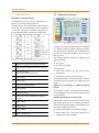
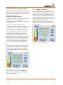
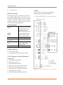
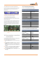
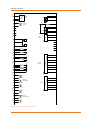
We take care of it.
2. Characteristics
2.1 Regulator functions
Multimaster system architecture
The REG-DPA is part of a range of devices that is
based on a standard hardware platform.
If multiple devices are connected through the system
bus E-LAN, every bus participant can be configured
or read from a single PC. In addition, several PCs can
access individual system participants (multimaster).
Figure 2:
Regulation of the detuning
A change in the grid’s switching status is recognized
by a change in the zero sequence voltage. The regulator repositions the Petersen coil while taking into
account the configurable conditions to the set detuning current.
Figure 1:
REG-DPA regulator functions
1
Voltage transducer (zero sequence voltage)
2
Position signal (resistance sensor) for the coil
3
Current transducer
(e.g. current through the P-coil)
4
Binary inputs
5
Power supply
6
Display and processing unit
7
Binary outputs
8
Analogue outputs
9
E-LAN connection (2 x RS485 with repeater
function)
10
COM1, RS232
11
COM2, RS232
12
COM3, RS485
13
Status - Signal (relay)
Page 2
The following data are displayed in addition to the
regulator’s status:
0
0
0
0
Coil position
Zero sequence voltage
Detuning (v)
Total active current in the grid over the fault
location (Iw)
0 The resonance curve and its parameters
The switching status is monitored through a complex
evaluation of the zero sequence voltage (value and
phase).
Regulation to percentage or absolute detuning
current:
The regulator positions the Petersen coil according
to the configured setpoint value and effective positioning tolerance.
Special requirements for the 110 kV grid
Additional parameters can be taken into account for
high-voltage grids, such as a maximum continuous
adjacent zero sequence voltage. The following conditions are also taken into account:
0 Value of the allowable zero sequence voltage
0 Compensation limit = Value of the detuning current that may not be exceeded
Characteristics