1
Adjusting the Petersen coil during the earth fault:
The regulator can be configured so that the Petersen-coil can be corrected by compensation value
during an earth fault. Additional corrections can be
made through binary inputs.
Parallel operation of Petersen coils:
A number of methods are available to control Petersen coils that are switched in parallel.
0 Parallel control with communication over E-LAN
(master-slave)
0 Parallel control without communication
0 Parallel control with recognition of external grid
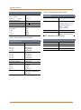
2.3 Regulator statistics
Statistics mode displays the most important sum
times and counters. This information can be used to
determine how many tuning procedures were carried out in which time frame, and how many were
successfully completed. It also enables you to recognize for how many tuning procedures the P-coil’s
adjustment range was insufficient.
Statistics mode also records the number of earth
faults and increases in residual watt current that
were carried out.
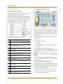
coupling (only with optional current injection)
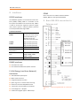
2.2 Recorder and logbook function
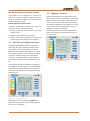
An integrated recorder continuously records the
progression of the zero sequence voltage and the
coil position. The time line diagram can both be
displayed and evaluated on the regulator or on a PC.
This integrated ‘grid spy’ enables long-term changes
in the zero sequence voltage to be recorded and
monitored. The configuration software WinEDC is
used to evaluate and archive recorded data on the
PC.
Figure 4:
Statistics Page 1/5
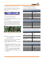
The progression of the zero sequence voltage Uen is
also displayed as a line diagram. The time grid (feed
rate) for the recording is adjustable. The stored values and the allocated time can be displayed using a
keyboard or PC.
Figure 3:
Recorderview
Important events are recorded in a logbook with
date and time information and can be displayed on
the screen or a PC statistic
Characteristics
Page 3