1
Step 1: Applying a decorrugation filter to yield an “error” grid
As an example, given a magnetic grid surveyed with a nominal line spacing of 150
meters (north-south survey lines), which has a line-to-line levelling problem, we want to
initially produce a grid that contains the levelling error. This is done using a Butterworth
high-pass filter combined with a directional cosine filter.
To perform this step, you will need to know how to use the MAGMAP 2D FFT package.
The parameters are discussed in more detail in the MAGMAP manual or the Online Help
if you need more information.
Following a rule of thumb, the Butterworth high-pass filter is set to four times the line
separation. This is done to pass wavelengths on the order of two to four line separations,
such as would result from a line-to-line levelling error. The directional cosine filter is set to
pass wavelengths only in the direction of the lines. Note that the North-South line
levelling error will produce wavenumbers in the East-West direction (azimuth 90).
Because levelling error is very directional, we are able to tighten the directional cosine
function (to an energy level of 0.5).
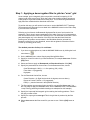
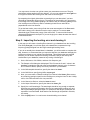
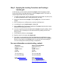
The detailed procedure for Step 1 is as follows:
1
If you have not already done so, load the MAGMAP.OMN menu by clicking the Load
menu button (
).
2
On the MAGMAP menu, select Step-by-step filtering|Define filters.
3
Specify a control file name for your filter definitions, for example decor.con. Click the
[OK] button.
4
Select two filters to apply as Butterworth and Directional Cosine. Click [OK].
5
Specify the parameters for the two filters. For the Butterworth filter, choose:
Cutoff Wavelength = 600 (i.e., 4 x line spacing (150) = 600);
Filter Order = 8 (suggested);
High-pass.
6
For the Directional Cosine filter, choose:
Centre Direction = 0; (flight lines' azimuth in degrees, see note above);
Degree of Cosine Function = 0.5 (suggested);
Pass (i.e., pass the features in the specified direction).
7
The filter settings are now saved in the control file you specified (decor.con). You
are now ready to apply the MAGMAP filters. On the MAGMAP menu, click MAGMAP
1-step Filtering (assuming that default settings are adequate for this example).
8
Specify the input total field magnetic grid containing the levelling problems. This is
the grid you want to filter.
9
Specify the output grid as error.grd. This is the grid that is produced by the filter
process.
10 Select decor.con as the filter control file you want to use. Click the [OK] button to
finish.