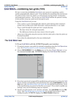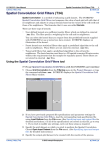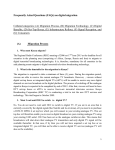
1
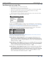
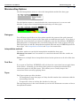
INTREPID User Manual
Library | Help | Top
Microlevelling (T33)
1
| Back |
Microlevelling (T33)
Top
Microlevelling applies corrections that are stored in a grid to traverse line data. The
usual purpose of this is to apply corrections obtained from a decorrugation process
(See Decorrugation (T32)) to the levelled line dataset. This enhances the traverse
line data by removing corrugations not detected by the conventional levelling process.
Microlevelling extrapolates correction values from the grid to an appropriate value
for each point in the traverse lines. It then applies the corrections to the point data.
This method is based on a paper by Brian Minty (Simple Micro-Levelling for
Aeromagnetic Data, B.R.S. Minty, Exploration Geophysics (1991), 22, 591-592)
Sources of correction data
You can use a corrections grid containing the actual values to extrapolate and
combine with the line data, or a levelled grid which has been corrected using a
decorrugation process. When you display a levelled grid, it resembles the product you
wish to obtain after the microlevelling process.
Using a corrections grid
Using a corrections grid for microlevelling is more straightforward than using a
levelled grid. Its values simply have to be extrapolated to match the data points of
the line dataset and then combined with in the line dataset values. A corrections
dataset produced by the INTREPID Decorrugation tool is already smooth and does
not really require the filter provided in the Microlevelling tool.
A possible disadvantage of corrections grids is their featureless appearance on the
screen. This, however, assists you to see geological features that the Decorrugation
tool has inadvertently treated as corrugations.
Obtaining corrections from a levelled grid
The Microlevelling tool will also work with an input grid representing the corrected or
levelled data.
An advantage of using levelled grids is that their appearance on the screen shows the
improvement that you are intending to entrench in the line data. You are therefore
able to visually verify the suitability of the grid for the process. On the other hand, it
does not clearly show you if the Decorrugation tool has inadvertently treated some
geological features as corrugations.
The levelled grid process is, however, more complex, and may introduce errors.
A number of line dataset data points with different values may contribute to a
particular grid cell. This variation in survey data within the area covered by a grid
cell may be valuable data, so you cannot simply substitute the levelled grid values in
all data points that fall within the cell's area. You need to determine the correction
component of the levelled grid values and subtract that from the survey data. This
introduces further complexity and possible error to the process.
Library | Help | Top
© 2012 Intrepid Geophysics
| Back |
INTREPID User Manual
Library | Help | Top
Microlevelling (T33)
2
| Back |
INTREPID calculates the corrections by extrapolating the grid values to match each
point, then subtracting the survey data from the extrapolated grid values to produce
the corrections. Because of its variations within grid cell areas, the survey data has a
much higher frequency content than the gridded data. The corrections that
INTREPID obtains will acquire this high frequency component. For the corrections
to be as close to pure decorrugation corrections as possible, the Microlevelling tool
must
•
Low pass filter them to remove the high frequency component and
•
Limit the magnitude of the corrections.
Discontinuities arising from microlevelling
Microlevelling may introduce some discontinuities or other irregularities to
individual microlevelled traverse lines.
Sources of discontinuities
•
The extrapolation of the grid corrections to match individual data points may give
very small irregularities of a wavelength equal to the grid cell size. These are
usually very minute.
•
If you restricted the dynamic range of the corrections in Decorrugation (See
Decorrugation (T32)) or other processes performed on the corrections grid, the
process may not have fully corrected for the corrugations.
•
If you used the INTREPID Subsection facility (See Subsections of datasets (T21))
during filtering, the filtering process may have interpolated corrections over gaps
created by the subsection process. This may introduce small discontinuities.
•
If the grid's extent does not encompass the extent of the survey data, you can
instruct INTREPID to extrapolate the corrections to the end points of the survey
data or taper them to zero. This may introduce small discontinuities.
Removing irregularities and discontinuities
To remove these irregularities, INTREPID calculates the corrections for an entire
traverse line and then low pass filters them before applying them. This effectively
smooths out any discontinuities. The wavelength of the filter must be sufficiently
long to remove the discontinuities but not longer than the actual minimum
wavelength of the corrections. This would remove some of the real corrections. A
minimum wavelength 1/2 to 1/4 (usually 1/2) of the streak length specified in
Decorrugation is usually adequate.
Levelling surveys together with Microlevelling
Though this tool was designed with microlevelling in mind, you can also use it to level
different surveys together. To do this:
Library | Help | Top
1
Grid each survey independently.
2
Use Grid Stitching to adjust the grid of survey B to the grid of survey A so they
represent a continuous surface (See Grid Stitch—combining two grids (T23)).
3
Treat this adjusted grid as though it were a fully levelled grid and use
Microlevelling to adjust its original survey data to it. This will transfer the
adjustments made by grid stitching to the original survey data.
© 2012 Intrepid Geophysics
| Back |
INTREPID User Manual
Library | Help | Top
Microlevelling (T33)
3
| Back |
The Microlevelling tool
>> To use Microlevelling with the INTREPID graphic user interface
1
Choose Microlevel from the Level menu in the Project Manager, or use the
command mlevel.exe. INTREPID displays the Microlevelling window.
2
If you have previously prepared file specifications and parameter settings for
Microlevelling, load the corresponding task specification file using Load Options
from the File menu. (See Specifying input and output files for detailed
instructions.) If all of the specifications are correct in this file, go to step 8. If you
wish to modify any settings, carry out the following steps as required.
3
Specify the input Z field to be corrected, the grid dataset to be used as a source of
corrections, the output corrected Z field and the output field for the correction
values if required. Use the corresponding options from the File menu. (See
Specifying input and output files for detailed instructions.)
INTREPID displays the grid containing the corrections in the Microlevelling
window.
You can zoom (enlarge an area of the display) and pan (examine different regions
while enlarged) if required to examine it before proceeding (See Zooming and
panning the grid display for details).
Library | Help | Top
4
Specify the parameters and filter type for the process using Parameters and Type
from the Filters menu (See Setting Microlevelling filter types and parameters
and Selecting Microlevelling filter types for details).
5
Specify whether the input grid is a levelled (corrected) grid or a grid dataset
containing the corrections. Choose the corresponding option from the Grid
Format menu. (See Microlevelling input grid format for details.)
6
Specify whether or not you require this process to be a test run (i.e., no changes to
the original data in the line dataset). Turn the Test Run option from the Options
menu on or off as required. (See Microlevelling Options.)
7
Specify whether you wish to use the taper facility to extrapolate over any data
gaps. If you require it, specify the taper distance in the dialog box that appears.
(See Microlevelling Options.)
© 2012 Intrepid Geophysics
| Back |
INTREPID User Manual
Library | Help | Top
8
Microlevelling (T33)
4
| Back |
When you have made specifications and settings according to your requirements,
choose Apply.
INTREPID will perform the corrections and display each line in the
Microlevelling window as it is processed. INTREPID colour codes the line display
to indicate the amplitude of the correction.
9
If you wish to record the specifications for this process in a .job file in order to
repeat a similar task later or for some other reason, use Save Options from the
File menu. (See Specifying input and output files for detailed instructions.)
10 If you wish to repeat the process, repeat steps 2–9, varying the parameters and/or
data files as required. Acquisition and tie lines need to be processed separately,
so you may need to repeat the process in order to correct both line types. (See
Displaying options and using task specification files).
11 To exit from Microlevelling, choose Quit from the File menu.
___
To view the current set of specifications choose Show from the Microlevelling window.
INTREPID displays them in a separate window. (See Displaying options and using
task specification files for details and an example of a set of specifications.)
You can view Help information by choosing options from the Help menu (See Help).
You can execute Microlevelling as a batch task using a task specification (.job) file
that you have previously prepared. See Displaying options and using task
specification files for details.
Library | Help | Top
© 2012 Intrepid Geophysics
| Back |
INTREPID User Manual
Library | Help | Top
Microlevelling (T33)
5
| Back |
Zooming and panning the grid display
You can enlarge and reduce the display (zoom in and out) and view different parts of
it (pan).
>> To zoom in and out (enlarge/reduce)
To zoom in (enlarge the display) choose Zoom In at the right edge of the
Microlevelling window. Each time you choose this button, INTREPID will enlarge
the display by one step.
To zoom out (reduce the display) choose Zoom Out at the right edge of the
Microlevelling window. Each time you choose this button, INTREPID will reduce the
display by one step.
>> To zoom in on a selected area of the display
Choose Zoom Area, then hold down the left mouse button and drag diagonally (corner
to corner) across the area that you wish to enlarge. INTREPID will enlarge the
selected region to fill the display area of the window.
>> To pan the display (view different parts)
The Pan/zoom indicator at the right of the Microlevelling window in the centre
consists of a small square within a larger square. The large square represents the
whole display and the small square the part visible on the screen. When you drag the
small square to a different part of the large square INTREPID shows the
corresponding part of the display.
If you have zoomed out to view the whole display, the small square may occupy the
whole of the large square and may therefore not be visible.
Library | Help | Top
© 2012 Intrepid Geophysics
| Back |
INTREPID User Manual
Library | Help | Top
Microlevelling (T33)
6
| Back |
Specifying input and output files
To use Microlevelling, you will need to specify
•
The Z field to be corrected in the line dataset,
•
The X and Y location data in the line dataset if there is no alias for these fields
•
The line type field of the line dataset (if required and there is no alias),
•
The grid dataset containing the corrections,
•
The line dataset field for saving the corrected Z values or the correction values.
Choose the options as required from the File menu.
In each case INTREPID displays an Open or Save As dialog box. Use the directory
and file selector to locate the file you require. (See "Specifying input and output files"
in Introduction to INTREPID (R02) for information about specifying files).
INTREPID will need to obtain information from the dataset aliases. The dataset
must have aliases identifying appropriate field files as follows.
Alias
Field
X
X coordinate (location)
Y
Y coordinate (location)
See "Vector dataset field aliases" in INTREPID database, file and data structures
(R05)for more information about aliases.
Specify Dataset—Open Original Z Use this to specify the Z field that is to be
corrected using the Microlevelling process. INTREPID will also prompt you to
specify a line type field (see instructions below). Select the fields from inside the
dataset directory. If you are using the Windows version, select a field marker file
with the extension ..LINE.
Specify Dataset—Open Input X, Y If there are no valid X and Y aliases specifying
the location files, or you wish to specify different X and Y fields, use these options.
Select the fields from inside the dataset directory. If you are using the Windows
version, select field marker files with the extension ..LINE.
Specify Dataset—Open Input Line type Use this to specify the line type field for
eliminating non-acquisition lines from the process. If you do not specify a line
type field INTREPID will process all traverse lines data. If you specify a line type
field, INTREPID will only process traverse lines whose line type is 2. Select the
field from inside the dataset directory. If you are using the Windows version,
select a field marker file with the extension ..LINE.
Library | Help | Top
© 2012 Intrepid Geophysics
| Back |
INTREPID User Manual
Library | Help | Top
Microlevelling (T33)
7
| Back |
Open Input Grid Use this to specify the grid dataset containing the corrections.
INTREPID will open the grid and display it in the Microlevelling window. The
grid will be located outside the line dataset directory. If you are using the
Windows version, select a grid marker file with the extension ..GRID.
Specify corrected Z, Specify Corrections Output Use one of these options to
specify the field for saving the corrected Z values or the correction values. You
may select only one of the options—INTREPID will output only one field from the
process. Specify the field inside the line dataset directory.
Load Options If you wish to use an existing task specification file to specify the
Microlevelling process, use this menu option to specify the task specification file
required. INTREPID will load the file and use its contents to set all of the
parameters for the Microlevelling process. (See Displaying options and using task
specification files for more information).
Save Options If you wish to save the current Microlevelling file specifications and
parameter settings as an task specification file, use this menu option to specify
the filename and save the file. (See Displaying options and using task
specification files for more information.)
Saving the corrections vs the corrected data
You can save the correction for each data point instead of the corrected value. You
can use the Profile Editor or Line Filter tool (See Profile Editor (T17) or Line Filtering
(T31)) to inspect the corrections for any unwanted features (generally a high
frequency component). To obtain the corrected data run Microlevelling again.
Microlevelling with 'oblique' datasets
If you are microlevelling an 'oblique' line dataset (one whose lines are not oriented
North–South or East–West), you must use an input grid that is rotated so that its
rows or columns are parallel with the acquisition lines.
If your input grid was produced by the Decorrugation tool and its source was
originally produced correctly as a rotated grid, do not perform any rotation on it
before using it as input to the Microlevelling tool. See "Using Decorrugation for
'oblique' line datasets" in Decorrugation (T32) and "Producing a rotated grid" in Old
Gridding (T22) for further information.
Specify the direction of the acquisition lines using the Nominal Strike parameter (See
Setting Microlevelling filter types and parameters for instructions).
Setting Microlevelling filter types and parameters
After extrapolating the grid data along each traverse line, INTREPID will apply a
low pass filter to it before combining it with the traverse line data. See Sources of
correction data and Discontinuities arising from microlevelling for discussion about
the purpose of this filter.
Library | Help | Top
© 2012 Intrepid Geophysics
| Back |
INTREPID User Manual
Library | Help | Top
Microlevelling (T33)
8
| Back |
Selecting Microlevelling filter types
Choose the Microlevelling filter type from the Type cascade in the Filter menu.
Naudy Use the Naudy filter.
Naudy–Fuller Use Naudy and Fuller filters in tandem. For low pass filters
INTREPID will apply the Naudy filter first followed by a Fuller filter. This gives
the best results but takes longer.
Fuller Use the Fuller filter.
Smoothed Fuller Use the Fuller filter. INTREPID uses subsampling of the data for
low pass filters. In this case a secondary Fuller filter will remove any introduced
high frequency noise.
We recommend that you use the Naudy–Fuller or smoothed Fuller filters.
See "Fuller filter" in INTREPID spatial and time domain filters and transformations
(R13) and "Naudy filter" in INTREPID spatial and time domain filters and
transformations (R13) for general information about the filters.
Filter parameters
Window size (wavelength) This parameter determines the size of the irregularities
you are removing. See Setting Microlevelling parameters for instructions.
Setting Microlevelling parameters
To set Microlevelling parameters, choose Parameters from the Filter menu.
INTREPID displays the Microlevelling Parameters dialog box.
Set the parameters according to your requirements then choose OK.
Library | Help | Top
© 2012 Intrepid Geophysics
| Back |
INTREPID User Manual
Library | Help | Top
Microlevelling (T33)
9
| Back |
.Secondary filter along correction INTREPID applies a low pass filter to the
extrapolated correction data to remove high frequency variations. This parameter
specifies the minimum wavelength (in metres) (highest frequency) allowable for
corrections data. INTREPID will remove data with a longer wavelength (lower
frequency).
A wavelength of about 1/2 to 1/4 (usually 1/2) of the minimum streak length
specified in the Decorrugation process is usually adequate.
This parameter corresponds to the window size parameter for the Fuller and/or
Naudy filter used in the process. See "Fuller filter" in INTREPID spatial and
time domain filters and transformations (R13) and "Naudy filter" in INTREPID
spatial and time domain filters and transformations (R13) for general information
about these filters.
Nominal Strike Use this to set the nominal strike (nominal bearing, direction) of the
acquisition lines in degrees East of North. INTREPID uses the value you specify
to define the nominal strike of the traverse lines to be adjusted.
INTREPID ignores those whose strike differs from the nominal strike by more
than ±10°. You therefore need to carry out the Microlevelling process separately
for acquisition lines and tie lines.
If you are microlevelling an 'oblique' line dataset (one whose lines are not oriented
North–South or East–West), see Microlevelling with 'oblique' datasets for details
about this process.
Minimum adjustment The minimum value for any correction (normally a negative
number). If INTREPID finds a correction that requires a negative adjustment of
greater magnitude than this minimum value, it will use a correction equal to the
minimum value. The minimum adjustment typically has the same absolute value
as the maximum adjustment (see below).
Maximum adjustment The maximum value for any detected correction (normally a
positive number). If INTREPID finds any correction greater than this maximum
value, it will set the correction equal to the maximum value. The maximum
adjustment typically has the same absolute value as the minimum adjustment
(see above).
For a correction whose value falls between the maximum and minimum
adjustments, INTREPID will use the value of the correction, not the maximum or
minimum adjustment value.
Microlevelling input grid format
Use the options in the Grid Format menu to specify whether the input grid contains
corrections or is a levelled grid
To select an option, choose it from the menu. After you have chosen an option, it will
acquire a selected option mark (check or tick) which you can see if you pull down the
menu again.
See Sources of correction data for a full discussion of correction vs levelled input
grids.
Library | Help | Top
© 2012 Intrepid Geophysics
| Back |
INTREPID User Manual
Library | Help | Top
Microlevelling (T33)
10
| Back |
Microlevelling Options
Use the Interpolation menu to select the interpolation method for data gaps.
Use the Options menu to control whether the current process is a test run and
whether to taper when interpolating/extrapolating over data gaps.
Data gaps
You will have gaps if there are data points outside the extent of the grid (external
gaps) or if the values of parts of the input grid are null (internal gaps). If you have a
gap in the correction data or it doesn't completely cover the line dataset, INTREPID
will extrapolate or interpolate the corrections along the line in the region of the gap.
The Taper process and the Interpolation method affect the way INTREPID processes
these gaps. See Interpolation method and Taper for instructions.
Interpolation method
Use these options to specify the interpolation method for data gaps.
Minimum curvature uses iterations of a convolution kernel until the results are
smooth.
Linear uses a simple linear interpolation based on the points on each side of the data
gap.
Test Run
If you turn on Test Run, INTREPID will calculate the corrections but not apply them
to the Z data. Normally you would use this option in conjunction with the Save
corrections option in the File menu. This allows you to visually inspect the
corrections before actually applying them.
Taper
The Taper option specifies whether:
•
To interpolate across data gaps as if they should contain data consistent with the
surrounding data OR
•
To taper the values to 0 along the border of a data gap
The tapering process is the same whether you select the minimum curvature or linear
interpolation method.
Library | Help | Top
© 2012 Intrepid Geophysics
| Back |
INTREPID User Manual
Library | Help | Top
Microlevelling (T33)
11
| Back |
>> To turn on Tapering
Choose Taper from the Options menu. INTREPID displays the Taper Distance
dialog box.
Specify the Taper distance in metres. Choose OK. The Taper option in the Options
menu should now display a tick. If you use Taper, INTREPID tapers values from the
edges of the gaps along the line down to zero over the specified distance.
>> To turn off Tapering
(assuming Taper is already on, showing a tick in the Option menu), Choose Taper
again from the Options menu. The Taper option in the Options menu should from
then display no tick. If Taper is off,
•
For internal gaps INTREPID will interpolate along the line between points on the
edges of the gap that do have corrections.
•
For external gaps, INTREPID will use the correction for the point closest to the
edge of the gap as the correction for the rest of the line.
Help
You can use the Help menu to display help text on the topics shown in the menu
illustration below.
Exit
To exit from Microlevelling choose Quit from the file menu.
Displaying options and using task specification files
Displaying options
>> To display the current file specifications and parameter settings
Choose Show in the Microlevelling window. INTREPID displays the current options
in a separate report window.
Library | Help | Top
© 2012 Intrepid Geophysics
| Back |
INTREPID User Manual
Library | Help | Top
Microlevelling (T33)
12
| Back |
Using task specification files
You can store sets of file specifications and parameter settings for Microlevelling in
task specification (.job) files.
>> To create a task specification file with the Microlevelling tool
1
Specify all files and parameters.
2
Preferably execute the task (choose Apply) to ensure that it will work.
3
Choose Save Options from the File menu. Specify a task specification file
(INTREPID will add the extension .job) INTREPID will create the file with the
settings current at the time of the Save Options operation.
For full instructions on creating and editing task specification files see INTREPID
task specification (.job) files (R06).
>> To use a task specification file in an interactive Microlevelling session
Load the task specification (.job) file (File menu, Load Options), modify any settings
as required, then choose Apply.
>> To use a task specification file for a batch mode Microlevelling task
Type the command mlevel.exe with the switch –batch followed by the name of the
task specification file.
For example, if you had a task specification file called surv329.job in the current
directory you would use the command
mlevel.exe –batch surv329.job
Task specification file example
Here is an example of a Microlevelling task specification file.
Process Begin
Name = microLevel
InputGrid = /disk1/surv/corr_grid1
ZIN = /disk1/surv/ebag_s/raw_mag
LineType = /disk1/surv/ebag_s/linetype
ZOUT = /disk1/surv/ebag_s/mlevel
Parameters Begin
FilterMethod = "SMOOTHEDFULLER"
InterpolationMethod = "MINIMUMCURVATURE"
CutOffWavelength = 1000.0
TaperCorrections = No
TaperLength = 500.0
MinimumCorrection = -30.0
MaximumCorrection = 30.0
GridBand = -1
StrikeDirection = 90.0
CorrectionGrid = Yes
TestRun = No
Parameters End
Process End
Library | Help | Top
© 2012 Intrepid Geophysics
| Back |
INTREPID User Manual
Library | Help | Top
Microlevelling (T33)
13
| Back |
Frequently asked questions
Q : What do I use for the corrected grid in microlevelling? Is a tie-line levelled
grid the one to use? If not how do I get a corrected grid for the microlevelling
process?
The input grid for Microlevelling should be a grid which is free of line to line busts.
Usually this will be the output grid generated from running the Decorrugation tool.
The Decorrugation tool typically takes as input a tie-line levelled grid (or the best
levelled grid you have) and removes linear features from it to produce a decorrugated
grid. The filter parameters in the decorrugation tool control the degree of
decorrugation (and possible loss of signal) that takes place. If you use the
decorrugation tool to output a Levelled grid (under Grid Output) you can visually
check it before doing the microlevelling. The Decorrugate tool has to work along grid
columns or rows so if your dataset was flown with angled lines you'll need to rotate
the grid.
The Microlevelling tool creates a new dataset field using the input decorrugated grid.
If you then grid that channel you should end up with essentially the same grid as the
input grid.
Library | Help | Top
© 2012 Intrepid Geophysics
| Back |