1
INTREPID User Manual
Library | Help | Top
INTREPID spectral domain operations reference (R14)
1
| Back |
INTREPID spectral domain operations reference (R14)
Top
In this chapter:
•
Tools using spectral domain operations
•
Notation used in this reference
•
The spatial and spectral domains
•
Spectral domain processes
•
Preparation of data for spectral transform
•
Post-filter transformation
•
Specifying the Earth's core magnetic field direction and intensity
•
Spectral domain filters available
•
Single derivative filters
•
Compound derivative filters
•
Tensor Component filters (reference)
•
Full and Partial tensor filters (reference)
•
Reduction filters (reference)
•
Horizontal and vertical components filters (reference)
•
Continuation filters (reference)
•
Filters for frequency ranges (pass filters)
•
Directional Filters
•
Complex filters
•
Vertical Integral filter (reference)
Tools using spectral domain operations
Parent topic:
INTREPID
spectral
domain
operations
reference (R14)
The following tools use spectral domain operations:
•
Spectral domain grid filters tool (GridFFT) (T40)
•
Line Filtering (T31)
•
Euler Deconvolution (T44)
•
Multi-scale edge detection wizard (T44a)
Notation used in this reference
Parent topic:
INTREPID
spectral
domain
operations
reference (R14)
Library | Help | Top
In this section:
•
Availability in INTREPID tools
•
Notation for filter formulas
© 2012 Intrepid Geophysics
| Back |
INTREPID User Manual
Library | Help | Top
INTREPID spectral domain operations reference (R14)
2
| Back |
Availability in INTREPID tools
Parent topic:
Notation used
in this
reference
The filters listed in this section carry one or two icons denoting whether they are
available in the Spectral Domain Grid Filters tool and/or the Line Filter tool.
This icon indicates that the filter is available in the Line Filter tool.
This icon indicates that the filter is available in the Spectral Domain Grid Filters tool.
This icon indicates that the filter is available for tensor data.
Notation for filter formulas
Parent topic:
Notation used
in this
reference
The following sections contain some formulas for the spectral domain filters. We have
used the following notation in these formulas:
w = input in spectral domain
F(w) = filter results (in spectral domain)
The spatial and spectral domains
Parent topic:
INTREPID
spectral
domain
operations
reference (R14)
In the spatial domain data is represented in a mathematical space where the
dimensions correspond to the three directions.
By analysing the frequency and direction of wave patterns in the data, using Hartley
or Fourier transformation, you can map a dataset into the spectral domain, where,
instead of distance, the dimensions correspond to increasing frequencies in the
corresponding directions. Instead of the original Z values of the data, high and low
values correspond to 'energy' of the data at the frequency concerned. Dimensions
corresponding to frequency are titled Fx, Fy, ... .
In this section:
Library | Help | Top
•
Data dimensions
•
Fundamental and Nyquist frequencies
•
Power spectrum graphs
© 2012 Intrepid Geophysics
| Back |
INTREPID User Manual
Library | Help | Top
INTREPID spectral domain operations reference (R14)
3
| Back |
Data dimensions
Parent topic:
The spatial and
spectral
domains
INTREPID tools support one and two dimensional data in the spectral domain.
•
The Spectral Domain Grid Filters tool uses two dimensional spaces (Fx, Fy)
corresponding to the dimensions of grid datasets. INTREPID represents energy
using pseudocolour or averages the energy for all directions and represents it in a
power spectrum graph.
•
The spectral domain filters in the Line Filter tool use one dimensional spaces (Ft)
corresponding to the data along a traverse line. INTREPID represents energy in
a power spectrum graph. The profile can be a time series, spatial series or just a
sample series.
•
A Fourier series is calculated to fit the Potential Field data using both cosines and
sines. Cosine terms dominate for integrations and low pass operations. Sines
dominate during derivatives. Each cell position has a complex coefficient that is a
best fit of the Fourier series terms to reproduce the observed signal. The
frequency method of fitting and filtering the data provides a superior method to
the more traditional polynomial and/or finite difference convolution methods.
Fundamental and Nyquist frequencies
Parent topic:
The spatial and
spectral
domains
See also
"Fundamental and Nyquist Frequencies of the Input Grid" in Spectral domain grid
filters tool (GridFFT) (T40)
"Querying lines and setting line options" in Line Filtering (T31)
Fundamental Frequency
The fundamental frequency is the lowest frequency (or longest wavelength) of
spectral data that you can represent in the data. If the longest dimension of the data
is L, then the longest wavelength is L, and the lowest frequency is 1/L.
For example, if the longest dimension is 150 cells and the cell size is 80 m, L = 12000
m and the fundamental frequency is 0.0000833 cy/m.
Nyquist Frequency
The Nyquist frequency is highest frequency (or shortest wavelength) of spectral data
that you can represent in the the data. If the grid cell size is S, then the shortest
wavelength is 2S, and the highest frequency is 1/(2S).
For example, if the cell size is 80m, the Nyquist wavelength is 160m and the Nyquist
frequency is 0.00625 cy/m.
Library | Help | Top
© 2012 Intrepid Geophysics
| Back |
INTREPID User Manual
Library | Help | Top
INTREPID spectral domain operations reference (R14)
4
| Back |
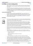
Power spectrum graphs
Parent topic:
The spatial and
spectral
domains
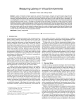
You can represent the energy of your data in the spectral domain in a graph plotted
against frequency. This is a power spectrum graph.
For two dimensional data it is common to combine the energies of the two frequency
dimensions to produce a radially averaged power spectrum. This will represent the
total energy for each frequency.
It is normal for the lower frequencies to generally have higher energy. This gives
power spectrum graphs their characteristic 'descending' shape.
INTREPID represents frequencies in cycles/km in the graphs.
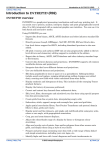
This illustration shows power spectra before and after a filter process. The input
dataset power spectrum is shown in blue (upper curve) and the filtered dataset power
spectrum in red (lower curve).
The tensor power spectrum graph has 3 before- and 3 after-traces:
Trace
Description
1
Eigenvalue 1
2
Eigenvalue 2
3
Rotations
For details about how INTREPID uses this concept, see:
"Data display tabs" in Spectral domain grid filters tool (GridFFT) (T40)
"Power Spectrum display" in Line Filtering (T31)
Library | Help | Top
© 2012 Intrepid Geophysics
| Back |
INTREPID User Manual
Library | Help | Top
INTREPID spectral domain operations reference (R14)
5
| Back |
Spectral domain processes
Parent topic:
INTREPID
spectral
domain
operations
reference (R14)
In this section:
•
Transforming data to the spectral domain
•
Spectral domain filters
•
Interpretation of frequency as depth
•
Returning data to the spatial domain
Transforming data to the spectral domain
Parent topic:
Spectral
domain
processes
INTREPID uses the Hartley transform to transform line data and the Fast Fourier
Transform (FFT) to transform grid data into the spectral domain.
Spectral domain filters
Parent topic:
Spectral
domain
processes
In the spectral domain you can process data according to its energy at each frequency
rather than its Z data value or spatial position. You can, for example, remove or
extract data of certain frequencies, or waves that are oriented in a particular
direction.
You can apply filters which can do one or more of the following:
•
Reduce or delete signals of a range of frequencies (Pass /Rolloff filters).
•
Shift the wave pattern so that when reverse transformed it appears to have been
collected at a different distance from the source (Continuation filters).
•
Calculate the derivatives of the wave pattern so that you can see changes in it
more clearly (Derivative filters).
•
Shift the apparent position of the data slightly to allow for the direction of the core
magnetic field at the time and place of acquisition (Reduction filters).
•
Reduce or delete signals that are oriented in a certain direction (two dimensional
data only) (Directional filters).
Essentially, a convolution in the spatial domain becomes a simple multiplication in
the spectral domain
Library | Help | Top
© 2012 Intrepid Geophysics
| Back |
INTREPID User Manual
Library | Help | Top
INTREPID spectral domain operations reference (R14)
6
| Back |
Interpretation of frequency as depth
Parent topic:
Spectral
domain
processes
Higher frequency features characterise sources of data that are closer to the surface,
and lower frequencies characterise deeper sources. Some of the reasoning for this is
as follows:
We can assume that the deeper sources are large because the signal from smaller
deep sources would attenuate. Since deeper sources are large and further away, they
would have fewer measurable changes and their signal would therefore be of lower
frequency.
Shallower sources may be smaller, or, even if large, their variations would be
measurable. We would therefore expect the signal frequency from these sources to be
higher.
Sources or variations in sources that are very small will have very high frequency
signals. These signals are of less interest to us, and may be classified as 'noise'.
We call shallow sources near surface sources and larger, deeper sources regional
sources.
In the Spectral Domain Grid Filters tool you can display the Spector Grant depth
estimate for any section of a power spectrum graph by clicking points on the graph.
Returning data to the spatial domain
Parent topic:
Spectral
domain
processes
After processing data in the spectral domain, INTREPID uses the reverse Hartley or
Fast Fourier Transformation back to the spatial domain. You can then spatially
locate features that have been enhanced using spectral domain filters.
Preparation of data for spectral transform
Parent topic:
INTREPID
spectral
domain
operations
reference (R14)
Library | Help | Top
In this section:
•
Introduction to pre-FFT processing
•
Expanding the data area
•
Detrending data values
•
'Periodic' dataset edges for spectral transform
•
Estimating values for data gap cells
•
Damping of dataset edges before spectral transform
•
Saving pre-FFT and FFT grid processing products for later reference
© 2012 Intrepid Geophysics
| Back |
INTREPID User Manual
Library | Help | Top
INTREPID spectral domain operations reference (R14)
7
| Back |
Introduction to pre-FFT processing
Parent topic:
Preparation of
data for
spectral
transform
Before transforming a dataset to the spectral domain, you must ensure that it
conforms to certain mathematical requirements.
Two dimensional data must be rectangular with certain mathematical requirements
for its numbers of rows and columns. You may therefore need to extrapolate data to
new dataset edges.
In addition to any extrapolation for correct shape, datasets must have an
extrapolated edge region. One dimensional data must have an extrapolated
extension at each end. Two dimensional data must have an extrapolated extension
on all sides.
The Z data curve or surface must be smooth and there may be no null values. If
there is an overall Z data trend in any direction, you will obtain better results if you
remove the trend before the filtering process.
Here is a detailed set of steps for the pre-filter transformation
1
If the data is in byte, integer or real (8 byte) format, INTREPID automatically
converts the values to real (4 byte) format, and record the original precision of the
data for conversion back after the filtering process.
2
INTREPID adds an extension to the ends or border of additional values. It
expands two dimensional data to a rectangular shape. See Expanding the data
area below for details.
3
INTREPID removes any trend from the data. See Detrending data values below
4
INTREPID creates values for the new data points or cells. It must do this in a
way which makes the newly enlarged line or dataset have a continuous wave
pattern. See 'Periodic' dataset edges for spectral transform below.
5
If required, INTREPID applies filters to the dataset to further damp the data at
the edges. See Damping of dataset edges before spectral transform below for more
information.
6
INTREPID can then perform the Hartley or Fast Fourier Transform on the
dataset. It will save a copy of the transformed dataset for later use if required
(Spectral Domain Grid Filters tool only).
For INTREPID tools reference about this topic, see:
"Pre FFT Grid Conditioning" in Spectral domain grid filters tool (GridFFT) (T40)
"Creating the extended region for filters" in Line Filtering (T31)
"Detrending and replacing trends" in Line Filtering (T31)
Library | Help | Top
© 2012 Intrepid Geophysics
| Back |
INTREPID User Manual
Library | Help | Top
INTREPID spectral domain operations reference (R14)
8
| Back |
Expanding the data area
Parent topic:
Preparation of
data for
spectral
transform
If you are preparing data for spectral transform you must expand the dataset to
dimensions that are multiples of 2 and/or 3 and/or 5. (Thus, suitable dimensions for a
dataset are 2ix3jx5k, where I, j and k are integers >= 0). If you are preparing a grid,
you must expand its area to become a rectangle.
To allow for creation of the continuous wave pattern (See 'Periodic' dataset edges for
spectral transform below), INTREPID adds a border of new cells all the way around
the existing grid dataset, or at each end of a traverse line.
INTREPID will expand the data by at least 10%, ensure that it is rectangular with
the dimensions specified above and initially assign null to the new data points or
cells.
We will refer to cells that contain null as data gap cells.
For INTREPID tools reference about this topic, see:
"Expanding the grid" in Spectral domain grid filters tool (GridFFT) (T40)
"Data extension method" in Line Filtering (T31)
"Pre FFT grid conditioning" in Multi-scale edge detection wizard (T44a)
Detrending data values
Parent topic:
Preparation of
data for
spectral
transform
Your dataset may have an overall trend in one or two dimensions. It could have one
of the following
•
No slope or trend (degree 0)
•
An overall slope or trend (degree 1)
•
A tendency to have steeper slopes at one end than the other (degree 2)
•
A slope down then up then down again (degree 3).
We recommend that you remove trends before using spectral transform.
For 0 degree detrending INTREPID simply subtracts the dataset mean from all
values in the dataset, recording the value of the mean for later restoration.
For degree > 0, INTREPID subtracts the dataset mean from all values in the dataset,
recording the value of the mean for later restoration. It then fits a polynomial to the
dataset in each direction and uses it in the detrending process. INTREPID stores up
to 10 polynomial coefficients for later trend reproduction (part of post-filter
transformation). INTREPID can reproduce trends corresponding to degrees 1 2 or 3.
The new Spectral Domain Grid Filters tool (GridFFT) always detrends the grid. The
Line Filter tool automatically detrends the data in most cases. The old Spectral
Domain Grid Filters tool (OldGridFFT) allows you to turn detrending on or off.
For INTREPID tools reference about this topic, see:
"Detrending" in Spectral domain grid filters tool (GridFFT) (T40)
"Detrending and replacing trends" in Line Filtering (T31)
Library | Help | Top
© 2012 Intrepid Geophysics
| Back |
INTREPID User Manual
Library | Help | Top
INTREPID spectral domain operations reference (R14)
9
| Back |
'Periodic' dataset edges for spectral transform
Parent topic:
Preparation of
data for
spectral
transform
If you are preparing for spectral transform, the new cells at the end or around the
edge of the dataset (see Estimating values for data gap cells) must acquire values that
fulfil the following criteria.
•
The new values must smoothly continue any wave patterns that exist in the
original data.
•
The wave patterns in the new values must 'wrap around' the dataset (in both the
East–West and North–South directions for two dimensional data). This means
that if you wrapped the dataset surface around to make a cylindrical shape in
either direction, the wave patterns would be continuous across the join of the two
edges. If the join becomes 'invisible' in this way, the dataset will become periodic
(i.e., if you rotate the dataset cylinder on its axis, your view of the dataset wave
patterns will repeat with each revolution).
INTREPID 'wraps' the dataset in each direction while it is estimating values for data
gap cells and smoothing the Z data surface, thus producing periodic data.
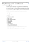
The illustration below uses contour lines to illustrate dataset periodicity for two
dimensional data.
Estimating values for data gap cells
Parent topic:
Preparation of
data for
spectral
transform
Cells in the dataset could be empty because
•
You have obtained or constructed the dataset in some way which left gaps or
•
They may have been created by the expanding data dimensions process (See
Expanding the data area).
Before performing spectral transform on the dataset, you must fill all data gaps. In
the Line Filter tool, INTREPID automatically fills the data gaps as explained in
Filling data gaps in line data.
In the Spectral Domain Grid Filters tool INTREPID can use either linear / cubic
interpolation or maximum entropy. See Linear interpolation of data gaps in a grid
(Arthur fill algorithm) and Maximum Entropy for data gaps in a grid.
INTREPID can remove the interpolated values during the post-filter transformation
if required. See Regenerating the data gaps below for details.
Library | Help | Top
© 2012 Intrepid Geophysics
| Back |
INTREPID User Manual
Library | Help | Top
INTREPID spectral domain operations reference (R14)
10
| Back |
Filling data gaps in line data
(Line Filter only) INTREPID uses linear, cubic or nearest neighbours interpolation to
fill data gaps within lines. For the data extension area you have the choice of zero
values or a mirror or 'flipped mirror' of the existing data at the end of the line.
Flipped mirror is the default method. See "Data extension method" in Line Filtering
(T31) and "Querying lines and setting line options" in Line Filtering (T31) for details.
Linear interpolation of data gaps in a grid (Arthur fill algorithm)
To calculate an estimate for a data gap cell INTREPID takes the average of four other
cells in the grid. One cell is to the North of the target cell, and the others to the East,
South and West respectively. With each iteration INTREPID uses a set of four cells
that is closer to the target cell than for the previous iteration. During each iteration
it calculates an estimate for every cell that does not contain original data. It
processes the cells one at a time along each row.
In the iterations at the largest cell distance, the four cells whose values used in the
calculation are at a distance of one half the width of the grid. In this case, the centre
cell of the grid receives the average value of the cells in the middle of each of the
edges of the grid. If the source cells would be off the edge of the grid, INTREPID
wraps the grid around and uses cells from the other side of the grid. By doing this,
INTREPID helps to make the dataset periodic at the edges (See 'Periodic' dataset
edges for spectral transform).
In the second set of iterations, the four cells are one quarter of the width of the grid
away from the target cell. In the third set of iterations, the four cells are one eighth of
the grid width away, and so on.
At the grid edges, the Arthur fill algorithm uses anti-symmetrical mirroring to
interpolate into the null edge zone.
For INTREPID tools reference about this topic, see:
"Fill method" in Spectral domain grid filters tool (GridFFT) (T40)
Maximum Entropy for data gaps in a grid
The Maximum Entropy process calculates values for data gaps using a linear
prediction from segments of rows or columns of original data (data vectors). It is
superior to other methods because the results have maximum entropy (i.e., they tend
to emulate the randomness of natural data rather than introducing distraction by
having their own intrinsic 'fill patterns').
INTREPID characterises the data with a finite number (default 10) of 'poles' that best
represent the original data's power spectrum (See Power spectrum graphs). It
interprets the power spectrum as being expanded in terms of a Laurent series. (The
order of the Laurent power series is the number of poles).
INTREPID uses whatever segments of rows or columns of original values it can find
between adjacent gaps as the vectors for interpolating values for the gaps. It bridges
gaps from both the left and right hand sides. It uses a linearly weighted average of
values on both sides to compute the values.
INTREPID first calculates the values for the data gaps using row segments (in the
East–West direction). Once it has computed all of the values it repeats the
calculation process using column segments (in the North–South direction).
For INTREPID tools reference about this topic, see:
"Fill method" in Spectral domain grid filters tool (GridFFT) (T40)
Library | Help | Top
© 2012 Intrepid Geophysics
| Back |
INTREPID User Manual
Library | Help | Top
INTREPID spectral domain operations reference (R14)
11
| Back |
Filling boundaries with source data in a regional dataset
If you have a large regional dateset and you are only using filters on a subset, you can
fill the boundaries with actual source data from the dataset instead of artificial data.
Damping of dataset edges before spectral transform
Parent topic:
Preparation of
data for
spectral
transform
Before the spectral transform process INTREPID can damp the edges of the Z data
curve or surface using a damping filter for rolling off the edges. This assists
INTREPID to obtain good periodic edges. (See 'Periodic' dataset edges for spectral
transform).
In normal practice detrending and filling the data gaps usually prepares the dataset
adequately. We have provided damping filters for your use if required.
INTREPID has two main roll-off methods, each of which has a number of filters. It is
normal to only use one of the methods.
Method
Description
Filters available
Expanded edge rolloff
Rolloff operation only on the edges of the grid
Cosine
Linear
Whole window damping
Damping operation across the whole grid
Cosine bell
Hanning
Hamming
Blackman
Triangle
For INTREPID tools reference about this topic, see:
"Edge damping rolloff options" in Spectral domain grid filters tool (GridFFT) (T40)
"Edge damping methods" in Line Filtering (T31)
Expanded edge rolloff
INTREPID’s edge damping rolloff operates only on the edges of a grid. INTREPID
uses a linear or cosine function to roll the grid edge values off to zero.
For INTREPID tools reference about this topic, see:
"Expanded edge roll-off" in Spectral domain grid filters tool (GridFFT) (T40)
Whole window damping
INTREPID’s damping window filters operate from the centre of the grid or line to the
edges.
INTREPID uses the following steps. :
1
Create a matrix of N coefficients 0, 1, ..., N–1 according to the function,
2
Superimpose the array of coefficients on the surrounding data points or cells,
3
Multiply each surrounding value by its corresponding coefficient,
4
Add the resulting values to obtain a new value for the data point or cell.
For INTREPID tools reference about this topic, see:
"Whole window roll-off" in Spectral domain grid filters tool (GridFFT) (T40)
"Edge damping methods" in Line Filtering (T31)
Library | Help | Top
© 2012 Intrepid Geophysics
| Back |
INTREPID User Manual
Library | Help | Top
We obtained these functions
INTREPID spectral domain operations reference (R14)
12
| Back |
from O'Neill (1988)1
Cosine Bell Filter (Spectral Domain Grid Filters only) This filter imposes a 'bell'
shaped cosine curve on the dataset. Here is a formula for a cosine bell filter
π
⎛ --- ( N – n )⎞
2
⎜
W ( n ) = cos ⎜ ---------------------⎟⎟
N
⎝
⎠
Where n = 0, 1, ..., I, ... , N–1
Hanning Filter This is a standard smoothing filter.
For Spectral domain grid filters,
( n + 0.5 )-⎞
W ( n ) = 0.5 ⎛ 1 – cos 2π
--------------------------⎝
⎠
N
Where n = 0, 1, ..., I, ... , N–1
For the Line Filter, where A is the window size in data points
⎧⎛
πx 2
⎪ ⎝ cos ------⎞⎠
A
h(x) = ⎨
⎪
⎩0
A
for x ≤ --2
otherwise
Hamming Filter (Spectral Domain Grid Filters only) This is a standard smoothing
filter. Here is a formula for a Hamming filter.
( n + 0.5 )
W ( n ) = 0.54 – 0.46 cos 2π
---------------------------N
Where n = 0, 1, ..., I, ... , N–1
Blackman Filter (Spectral Domain Grid Filters only) You can use this filter for
datasets that do not suit the Hamming and hanning filters. Here is a formula for
a Blackman filter.
( n + 0.5 -)
W ( n ) = 0.42 – 0.5 cos 2π
--------------------------N–1
Where n = 0, 1, ..., I, ... , N–1
1.O'Neill, Mark A., Faster Than Fast Fourier, Byte, April 1988, 293–300.
Library | Help | Top
© 2012 Intrepid Geophysics
| Back |
INTREPID User Manual
Library | Help | Top
INTREPID spectral domain operations reference (R14)
13
| Back |
Bartlett / Triangular Filter This filter is relatively fast but of lower quality.
Here is a formula for a triangular filter as used for the filled boundary portion of the
grids.
( n + 0.5 -)
W ( n ) = 2-----------------------N
W( N – n – 1) = W( n)
Where n = 0, 1, ..., I, ... , N/2.
Parzen Window (Line Filter only) This is a polynomial filter
⎧ x 3
⎪ ⎛ ---⎞
⎪ ⎝ A⎠
W(x) = ⎨
3
⎪ ⎛ --x-⎞ 2
⎛ x⎞
⎪ 6 ⎝ A⎠ – 6 ⎝ --A-⎠
⎩
A
for 0 < x ≤ --2
A
for --- < x < A
2
Where
A is the window size in data points;
W(x) is the weight at point x to apply in the rolloff region.
Saving pre-FFT and FFT grid processing products for later reference
Parent topic:
Preparation of
data for
spectral
transform
Saving pre-FFT processing products
During the pre-FFT processing of a grid, INTREPID saves copies of the input grid
after it has:
•
Detrended, expanded and filled the new cells, and again after it has
•
Completed the edge roll-off process.
INTREPID always saves the data as INTREPID grid datasets. After use, INTREPID
normally deletes these grids. You can usually keep them for debugging, quality
control or some other purpose if you want. Most INTREPID spectral domain tools
have options for keeping these grids.
Saving FFT of input grid dataset
INTREPID saves the spectral domain–transformed grid in a grid datsaset, to use as
input for the filtering operation. After use, INTREPID normally deletes this grid.
If you want to perform a number of filtering operations on a grid, you can save time
by keeping a copy of the spectral domain–transformed grid. You can use this as input
for as many filtering operations as you like without having to go through the pre-FFT
processing and the FFT itself each time.
You may also choose to save the FFT of the input grid for examination or a quality
check on the processing.
To re-use the saved copy of the spectral domain–transformed grid, simply specify it as
your input grid file. INTREPID automatically detects that it is already transformed
and skips the preparation and FFT stages.
Library | Help | Top
© 2012 Intrepid Geophysics
| Back |
INTREPID User Manual
Library | Help | Top
INTREPID spectral domain operations reference (R14)
14
| Back |
—Notes about spectral domain–transformed grids
These spectral domain grids have the same number of rows and columns as the
expanded spatial domain grids before the transformation (See "Expanding the data
area" in INTREPID spectral domain operations reference (R14)). INTREPID exploits
the symmetry in the spectral domain transformed data to achieve this.
You can examine the spectral domain grids using visualisation tools in the same way
as you would a spatial domain grid.
INTREPID records the pre-FFT process options and the name of the source grid in
the ..GRID or .ISI file of the spectral domain grid dataset. This enables you to reuse the spectral domain grid dataset for input and still return the results to the
spatial domain in a form that matches the input grid.
The FFT of the input grid two-band grid file. Band 1 is the real component, and band
2 is the imaginary.
Post-filter transformation
Parent topic:
INTREPID
spectral
domain
operations
reference (R14)
After applying grid filters to a dataset, you will normally wish to transform the
dataset back from the spectral domain to the spatial domain. This can include
•
Reverse spectral transform restoring the data to the spatial domain,
•
Removing the cells added around the edge of the grid,
•
Restoring null value to cells within the grid that were originally null,
•
Where appropriate, restoring a trend that was removed for the spectral transform
process, and replacing the mean of the dataset by adding the previously removed
mean to all cell values.
In the Spectral Domain Grid Filters tools (OldGridFFT amd GridFFT) you can turn
some or all the above stages of the operation on or off individually. See "Post-filter
transformation options" in Spectral domain grid filters tool (GridFFT) (T40)
In the Line Filter tool, the reverse transform process automatically includes the
above steps. It has no options for you to specify.
After the above processes are complete INTREPID restores the dataset to byte,
integer or real (8 byte) if it was originally converted from one of these formats to real
(4 byte) format for the spectral transform process.
The following sections describe the post-filter transformation processes in detail.
In this section:
Library | Help | Top
•
Reducing the dataset
•
Regenerating the data gaps
•
Reproducing the trend
© 2012 Intrepid Geophysics
| Back |
INTREPID User Manual
Library | Help | Top
INTREPID spectral domain operations reference (R14)
15
| Back |
Reducing the dataset
Parent topic:
Post-filter
transformation
After the reverse transform to the spatial domain you can remove the extension at the
traverse line ends or around the border of the grid.
INTREPID cannot restore any irregular shape of a grid dataset. It will remove
interpolated cells from the edge of the dataset. The reduced dataset will be
rectangular in shape with dimensions equal to the extent of the original dataset. All
cells in the reduced dataset that were not in the original will retain their interpolated
values unless you regenerate the data gaps (See Regenerating the data gaps below). If
you regenerate the cells, INTREPID will assign null to them.
Regenerating the data gaps
Parent topic:
Post-filter
transformation
After you reduce the traverse line or dataset to its original dimensions (see Reducing
the dataset), there may still be interpolated values created during the pre-filter
transformation. You can set the value of these interpolated data points or cells to
null if required.
For INTREPID tools reference about this topic, see:
"Regenerating the data gaps" in Spectral domain grid filters tool (GridFFT) (T40)
Reproducing the trend
Parent topic:
Post-filter
transformation
The pre-filter transformation included subtracting the mean from all values in the
dataset. It may also have removed trends in the dataset (See Detrending data
values). You can add the mean back and restore the trends as part of the post-filter
transformation.
For some filtering processes, such as those in which the units are changed, there is no
sense in attempting to reproduce the trend. These processes include:
•
Derivatives,
•
Use of high pass type filters which output high frequency data,
•
Pseudo gravity,
•
Susceptibility.
For INTREPID tools reference about this topic, see:
"Reproducing the trend" in Spectral domain grid filters tool (GridFFT) (T40)
"Detrending and replacing trends" in Line Filtering (T31)
Specifying the Earth's core magnetic field direction and intensity
Parent topic:
INTREPID
spectral
domain
operations
reference (R14)
If you wish to use the Reduction (to pole or equator), Vertical or Horizontal
Components, Susceptibility or Pseudo Gravity filter (See corresponding sections
below) you must specify the intensity and direction of the Earth's core magnetic field
at the mid point of the dataset.
INTREPID can automatically calculate this for you using one of the Geomagnetic
Reference Field (GRF) models, the location of the dataset you are processing and the
survey date and height.
See The geomagnetic reference field in INTREPID (R15) for information about the
GRF models and the way INTREPID tools use them.
For INTREPID tools reference about this topic, see:
"IGRF Calculator" in Spectral domain grid filters tool (GridFFT) (T40)
"Reduction to the Pole filter" in Line Filtering (T31)
Library | Help | Top
© 2012 Intrepid Geophysics
| Back |
INTREPID User Manual
Library | Help | Top
INTREPID spectral domain operations reference (R14)
16
| Back |
Spectral domain filters available
Parent topic:
INTREPID
spectral
domain
operations
reference (R14)
The following sections describe the spectral domain filters available in INTREPID
tools.
For INTREPID tools reference about this topic, see:
"GridFFT filters overview" in Spectral domain grid filters tool (GridFFT) (T40)
"Standard spectral domain filters" in Line Filtering (T31)
Single derivative filters
Parent topic:
INTREPID
spectral
domain
operations
reference (R14)
Calculating derivatives of survey data removes unwanted low frequency information
and shows the edges of anomalies.
Surveyed areas which do not have anomalies display no change in magnetic field and
thus have a derivative (gradient) of zero. At the edge of an anomaly, the data will
change, and the gradient will be non-zero. Thus an area which has a non-zero
gradient will clearly outline an anomaly.
Calculating derivatives will also enhance near surface features because they change
more frequently.
The measured location of a magnetic anomaly will be more accurate if you also apply
a Reduction to the Pole filter to the data (See Reduction filters (reference) below).
For INTREPID tools reference about this topic, see:
"Vertical derivative filter (GridFFT)" in Spectral domain grid filters tool (GridFFT)
(T40)
"Horizontal derivative filter (GridFFT)" in Spectral domain grid filters tool (GridFFT)
(T40)
"Vertical Derivative filter (gradient filters)" in Line Filtering (T31)
"Horizontal Derivative filter (gradient filters)" in Line Filtering (T31)
In this section:
Library | Help | Top
•
Vertical derivative filter (including fractional vertical derivative) (reference)
•
Horizontal derivative line filter (reference)
•
Generalised horizontal derivative filter (reference)
© 2012 Intrepid Geophysics
| Back |
INTREPID User Manual
Library | Help | Top
INTREPID spectral domain operations reference (R14)
17
| Back |
Vertical derivative filter (including fractional vertical derivative) (reference)
Parent topic:
Single
derivative
filters
The Vertical derivative is the derivative of the transformed Z data with respect to
height. Even though you will only have data collected at one height, INTREPID can
still calculate results for this filter.
A useful feature of INTREPID is its ability to calculate fractional derivatives (e.g.,
the 1.5th derivative). While this concept may make little sense in everyday
mathematics, it is possible in practice for INTREPID to calculate a fractional
derivative. Our geophysicists have found that the fractional derivative is a powerful
tool. A fractional derivative, (e.g., 1.5th ) can be superior to a 1st or 2nd derivative for
revealing certain anomalies.
Your choice of derivative order must be largely a function of the acquisition quality of
your data. For example, if the data is poor, the 1st derivative might be too severe. In
this case the 0.7 derivative would still give the insight but would yield more coherent
results.
For INTREPID tools reference about this topic, see:
"Vertical derivative filter (GridFFT)" in Spectral domain grid filters tool (GridFFT)
(T40)
"Vertical Derivative filter (gradient filters)" in Line Filtering (T31)
Vertical derivative filter—parameters
Parameter
Description
Order of Differentiation
Use this to specify the order of the differentiation.
The default and most commonly used order is 1. The
Order of Differentiation must be a positive number.
Horizontal derivative line filter (reference)
Parent topic:
Single
derivative
filters
(Line Filter only) The Horizontal Derivative is the derivative with respect to survey
distance or time (depending on the resampling method selected in the Line Filter
tool).
For INTREPID tools reference about this topic, see:
"Horizontal Derivative filter (gradient filters)" in Line Filtering (T31)
Library | Help | Top
© 2012 Intrepid Geophysics
| Back |
INTREPID User Manual
Library | Help | Top
INTREPID spectral domain operations reference (R14)
18
| Back |
Generalised horizontal derivative filter (reference)
Parent topic:
Single
derivative
filters
(GridFFT Spectral Domain Grid Filters only) The Generalised Horizontal Derivative
is the derivative with respect to distance in the Azimuth direction of the transformed
Z data.
For INTREPID tools reference about this topic, see:
"Horizontal derivative filter (GridFFT)" in Spectral domain grid filters tool (GridFFT)
(T40)
Generalised horizontal derivative—parameters
Parameter
Description
Order of Differentiation
Use this to specify the order of the differentiation.
The default and most commonly used order is 1. The
Order of Differentiation must be a positive number.
Direction or Azimuth
This defines the direction for the derivative
Hilbert Transform
The Hilbert transform has a variety of applications. In mathematics and in signal
processing, the Hilbert transform of a real-valued function, s(t), is another realvalued function in the same domain. The Hilbert transform is named after the
renowned mathematician David Hilbert.
Since the application of two Hilbert transformations in succession reverses the
phases of all components, it follows that the result will be the negative of the original
function. Similarly the application of four Hilbert transformations in succession
restores the original function. We use the phase shift of the Hilbert transform in
extended Euler to create an East and a North phase shifted derivatives of the
observed potential field.
Generalised Hilbert Transform —parameters
Parameter
Description
Direction or Azimuth
This defines the direction for the transform
Reference: Bracewell pg 267.
Compound derivative filters
Parent topic:
INTREPID
spectral
domain
operations
reference (R14)
These filters combine the results of a number of single derivative filters. INTREPID
calculates the single derivative filters in the spectral domain and combines them back
in the spatial domain after the reverse transformation. The addition of Hilbert
transforms to any or all of the following has been made to allow users to see what
transforms are being made in the Euler tool.
In this section:
•
Total horizontal derivative filter (reference)
•
Analytic signal filter (reference)
•
Library | Help | Top
Tilt Angle (Phase Map) (reference)
© 2012 Intrepid Geophysics
| Back |
INTREPID User Manual
Library | Help | Top
INTREPID spectral domain operations reference (R14)
19
| Back |
Total horizontal derivative filter (reference)
Parent topic:
Compound
derivative
filters
(GridFFT Spectral Domain Grid Filters only)
The Total Horizontal Derivative filter has the following steps:
1
INTREPID computes two separate derivative grids in the spectral domain—
Horizontal Derivatives for ‘X’ or ‘East’ and ‘Y’ or ‘North’.
2
INTREPID transforms these intermediate files back to the spatial domain.
In the spatial domain, INTREPID combines the two derivative grids to make the
Total Horizontal Derivative output grid.
For INTREPID tools reference about this topic, see:
"Total horizontal derivative filter (GridFFT)" in Spectral domain grid filters tool
(GridFFT) (T40)
3
Expressed mathematically, the THD is as follows
f = grid cell value
∂f
----∂x
= 1st horizontal derivative with azimuth = 0
∂f
----∂y
= 1st horizontal derivative with azimuth = 90
The total horizontal derivative is
∂f ⎞
∂f
⎛ ----+ ⎛ -----⎞
⎝ ∂x⎠
⎝ ∂x⎠
2
2
This filter has no parameters.
Library | Help | Top
© 2012 Intrepid Geophysics
| Back |
INTREPID User Manual
Library | Help | Top
INTREPID spectral domain operations reference (R14)
20
| Back |
Analytic signal filter (reference)
Parent topic:
Compound
derivative
filters
(GridFFT Spectral Domain Grid Filters only)
The analytic signal filter category has three related options:
•
Analytic Signal
•
Tilt Angle (Phase Map)
•
Total Horizontal Gradient of Tilt Angle
Analytic Signal (reference)
Computing the analytic signal filter consists of the following steps:
1
INTREPID computes three separate derivative grids in the spectral domain—
horizontal derivatives for ‘X’ or ‘East’ and ‘Y’ or ‘North’ and the first vertical
derivative.
2
INTREPID transforms these intermediate files back to the spatial domain.
In the spatial domain, INTREPID combines the three derivative grids to make
the analytic signal output grid.
Expressed mathematically, the analytic signal is as follows:
3
f = grid cell value
∂f
----∂x
= 1st horizontal derivative with azimuth = 0
∂f
----∂y
= 1st horizontal derivative with azimuth = 90
∂f
----∂z
= 1st vertical derivative.
analytic signal =
∂f ⎞
∂f-⎞
∂f ⎞
⎛ ----⎛ ---⎛ ----⎝ ∂x⎠ + ⎝ ∂y⎠ + ⎝ ∂z⎠
2
2
2
This filter has no parameters.
Tilt Angle (Phase Map) (reference)
Computing the tilt angle filter consists of the following steps:
1
INTREPID computes three separate derivative grids in the spectral domain—
horizontal derivatives for ‘X’ or ‘East’ and ‘Y’ or ‘North’ and the first vertical
derivative.
2
INTREPID transforms these intermediate files back to the spatial domain.
3
In the spatial domain, INTREPID combines the East and North derivative grids
to make the Total Horizontal Derivative output grid.
4
In the spatial domain, INTREPID computes the tilt angle from the Total
Horizontal Derivative and the Vertical Derivative value, using the following
formula :
atan(VD/Total Horizontal Derivative))
As can be seen, this filter is closely related to the Analytic Signal, and is therefore
included with the Analytic Signal in the user interface. The tilt angle shows the
character of the signal phase, and it functions as a good boundary edge sharpener.
This filter has no parameters.
Library | Help | Top
© 2012 Intrepid Geophysics
| Back |
INTREPID User Manual
Library | Help | Top
INTREPID spectral domain operations reference (R14)
21
| Back |
Total Horizontal Gradient of Tilt Angle Angle (reference)
Grid Filter also offers the advanced feature of calculating the Total Horizontal
Derivative of the Tilt angle.
For INTREPID tools reference about this topic, see:
"Analytic signal filter (GridFFT)" in Spectral domain grid filters tool (GridFFT) (T40)
Euler Deconvolution (T44)
Tensor Component filters (reference)
Parent topic:
INTREPID
spectral
domain
operations
reference (R14)
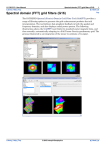
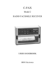
INTREPID has a range of spectral domain methods to convert the vertical component
of either a Gravity or a TMI observation to any of the curvature gradients (tensor
gradients).
The following image shows the Fourier domain weights that we use to achieve the
required output.
You can use the Spectral Domain Grid Filters tool (GridFFT) tool with full tensor
grids as well as ordinary scalar grids. For information about tensor grid structure, see
"Tensor grid dataset structure" in INTREPID database, file and data structures
(R05).
Currently, when calculating a tensor component, the GridFFT tool only produces a
single component output grid, and not a full tensor grid. It is not difficult to construct
a full tensor grid. You can use the Spreadsheet Editor function newTensor() to do
this job if you require it. See INTREPID expressions and functions (R12). First load
each of the component grids, then create the new full, tensor grid.
You can use the Gridding tool to create a full tensor grid from tensor profile data.
GridFFT offers a choice of filters, depending upon grid data type, so that it can, for
example, complete tensor integration of a full tensor grid. To do the integration,
INTREPID uses multiple inputs (Txz,Tyz,Tzz) to create one output (Tz).
In this rarely documented process, during research and testing to configure the
GridFFT tool, we experimented with the transfer function weights to balance the
contributions of each channel, giving slightly more weight to the Tzz contribution,
compared to the other partial derivatives.
The next generation gravity gradiometers can measure torsional gradients, for
example, Tzz – Txx. INTREPID provides the full range of conversions to and from
these compound gradients.
Library | Help | Top
© 2012 Intrepid Geophysics
| Back |
INTREPID User Manual
Library | Help | Top
INTREPID spectral domain operations reference (R14)
22
| Back |
Tensor Query filters (reference)
These filters convert vertical gravity to any of the five independent gravity tensor
components. You can use milligals or Eötvös. These filters only work on a single band
grid
You can also convert specific combinations of FTG or FALCON tensor components
into Tz or Tzz.
The measurement unit of gravity gradient is the Eötvös (Eö), being 1 nm/sec2/m,
equivalent to a gradient of 1 mgal over 10 km.
1 Eö = 1 mgal/10 km = 0.1 mgal/km = 0.0001 mgal/m
The following table contains possible inputs and ouputs for this filter.
Input
Output
Tz
Txx Txz Tyy Tyz Tzz Txy
Tzz – Txx
Tzz
Tzz – Tyy
Tzz
Full and Partial tensor filters (reference)
Parent topic:
INTREPID
spectral
domain
operations
reference (R14)
When filtering full tensor grids, be careful to state the correct coordinate frame of
reference. For example, if you are integrating Txz to get Tz, you need to apply the
appropriate sign correction for the direction of Z (up or down).
Make sure you are certain, also, whether the dataset was constructed with a right- or
left-handed system and therefore whether Txx is, in fact T east east.
See "Vector and tensor field data coordinate conventions" in INTREPID database, file
and data structures (R05)
Some INTREPID standard Fourier filters, such as Low, High and Band Pass, are
available for full tensor grids, as well as the Tensor Integral filter.
Library | Help | Top
© 2012 Intrepid Geophysics
| Back |
INTREPID User Manual
Library | Help | Top
INTREPID spectral domain operations reference (R14)
23
| Back |
Full Tensor Integration Query (FTG or other full tensor grids)
This filter integrates the partial derivatives of the tensor curvature gradients to
estimate either the vertical component of gravity, the total magnetic intensity or the
gravity and magnetic potentials.
This filter is only available for full tensor grids such as FTG or IPHT (magnetic
tensor). A second version of this filter is implemented for the Falcon partial tensor.
Query
Output
Description
Tez, Tnz, Tzz to Tz
Tz
Compute vertical gravity Tz from three
tensor components (Most accurate)
Tez, Tnz, to Tz
Tz
Compute vertical gravity Tz from two
tensor components
Tez to Tz
Tz
Compute vertical gravity Tz
Tnz to Tz
Tz
Compute vertical gravity Tz
Tzz to Tz
Tz
Compute vertical gravity Tz
Tensor to TMI
TMI (nT)
Compute total magnetic intensity from
magnetic tensor gradients
Tensor to Potential
Potential
Compute the gravity or magnetic
potential
To execute the full tensor integration query the steps are:
Library | Help | Top
•
Load a full tensor grid ie FTG (check that the tensor coordinate system is correctly
set ie END for FTG. The tensor coordinate system can be set in Project Manager.
•
Select the Full Tensor integration filter from the filter list (it will not be visible if
you did not load a full tensor grid).
© 2012 Intrepid Geophysics
| Back |
INTREPID User Manual
Library | Help | Top
Library | Help | Top
INTREPID spectral domain operations reference (R14)
24
| Back |
•
Choose a query from the Properties list. Tz can be estimated using between one
and three tensor components. The three components option (Tez, Tnz, Tzz to Tz)
is considered optimum, preserving longer wavelength features more accurately.
•
For the FTG and Magnetic tensors it is also possible to calculate the gravity or
magnetic potential.
•
Tensor to TMI will calculate TMI from the full magnetic tensor
© 2012 Intrepid Geophysics
| Back |
INTREPID User Manual
Library | Help | Top
INTREPID spectral domain operations reference (R14)
25
| Back |
FALCON Partial Tensor Transform Query
This filter integrates the partial derivatives of the falcon NE and UV tensor curvature
gradients to estimate the vertical gravity gradient (Gdd), the vertical component of
gravity (gD), the gravity potential and other tensor and QC related products
summarised in the table below. The user can choose the average of the FALCON A or
B measurements for the calculations (default) or the individual A or B measurements
separately.
Query
Output
Description
Falcon A & B to FTG
FTG Tensor
Creates FTG full tensor grid (END) from the
Falcon partial tensor grid (NED)
Falcon to Tz
Tz (gD)
Compute z component - vertical gravity (gD)
Falcon to Tx
Tx
Compute x component of gravity
Falcon to Ty
Ty
Compute y component of gravity
Falcon to Txx
Txx
The xx component of gravity gradient tensor
Falcon to Txy
Txy
The xy component of gravity gradient tensor
Falcon to Txz
Txz
The xz component of gravity gradient tensor
Falcon to Tyy
Tyy
The yy component of gravity gradient tensor
Falcon to Tyz
Tyz
The yz component of gravity gradient tensor
Falcon to Potential
Gravity
potential
Compute the gravity potential
Falcon to Txy
Txy (GNE)
Falcon Average NE (ANE+BNE)/2
Falcon to GUV
GUV
Falcon Average UV (AUV+BUV)/2
Falcon Phase Check
Gzz/iGzz
Falcon phase QC - check the phase
relationship of NE and UV before TC
To execute the FALCON tensor query the steps are:
Library | Help | Top
•
Load a FALCON tensor grid (check that the tensor coordinate system is correctly
set ie NED). The tensor coordinate system can be set in Project Manager.
•
Select the FALCON transform query filter from the filter list (it will not be visible
if you did not load a FALCON tensor grid)
© 2012 Intrepid Geophysics
| Back |
INTREPID User Manual
Library | Help | Top
Library | Help | Top
INTREPID spectral domain operations reference (R14)
26
| Back |
•
Select the transform query from the Component drop down list
•
Select the units for the chosen output ie Falcon to Tz (gD) would normally be
output in mGals.
•
The Butterworth filter option is not currently active and cannot be stacked with
Falcon query operations. 2D filtering of the FALCON tensor grid must be
completed using the separate tensor aware Butterworth filter if required
Butterworth filter (reference).
•
Choose whether to use the Average A+B signal or the FALCON A or B
measurements separately.
•
Step back to the Grid Conditioning Tab and you will observe that the Fill Method
has been set automatically to Optimise Fill Tensor. This method ensures that the
Fourier padding honours the tensor physics and improves significantly the long
wavelength accuracy of Tz (gD) during transformation.
•
Step forward to the Output Grid Dataset option
© 2012 Intrepid Geophysics
| Back |
INTREPID User Manual
Library | Help | Top
•
Library | Help | Top
INTREPID spectral domain operations reference (R14)
27
| Back |
The default output is a single band grid. In the Falcon to Tz (gD) and Falcon to
Tzz (Gdd) query cases the user can choose to output a two band grid
(IEEE4ByteComplex or IEEE8ByteComplex). In this case the first (Real) band
will contain the Tz (gD) or Tzz (Gdd) components and the second (Imaginary)
band contains the portion of the signal that remained (was not fitted) after the
transform. This second band can be thought of as the transform error and may be
examined to determine if real signal remains or whether it just contains noise.
© 2012 Intrepid Geophysics
| Back |
INTREPID User Manual
Library | Help | Top
INTREPID spectral domain operations reference (R14)
28
| Back |
Reduction filters (reference)
Parent topic:
INTREPID
spectral
domain
operations
reference (R14)
If you are taking magnetic readings from an aircraft, the reading at any point will be
a composite of the magnetism of nearby objects under the ground and the Earth's core
magnetic field. Except near the poles, the magnetic field direction is not vertical.
This will displace the measured location of any magnetic source near the aircraft.
For INTREPID tools reference about this topic, see:
"Reduction filter (GridFFT)" in Spectral domain grid filters tool (GridFFT) (T40)
"Reduction to the Pole filter" in Line Filtering (T31)
In this section:
•
Reduction filters—parameters
•
IGRF field inclination limit for amplitude calculation (for surveys near the
Equator)
•
Reduction to the Pole (reference)
•
Variable reduction to the pole
You can use a Reduction filter to correct this location error. Reduction filters use the
parameters listed below.
Reduction filters—parameters
Parent topic:
Reduction
filters
(reference)
The following table shows the reduction filter parameters. See also IGRF field
inclination limit for amplitude calculation (for surveys near the Equator)
Parameter
Description
Field Intensity,
Inclination for input data,
Declination for input data
These are values for the Earth’s magnetic field corresponding to the
input data. Some INTREPID tools use Field Intensity automatically
without requiring user input. You can specify these manually or
calculate them from the IGRF or other model (See Elevation and Date
parameters).
Elevation,
Date
You can use the IGRF or other model to calculate values for the
Earth’s magnetic field corresponding to the input data. This requires
the survey elevation and date. See The geomagnetic reference field in
INTREPID (R15) for information about the GRF models, the way
INTREPID tools use them and specific information about the three
parameters.
Latitude for amplitude
limit
(Reduction to the Pole only) See IGRF field inclination limit for
amplitude calculation (for surveys near the Equator)
Target inclination,
Target declination
Some INTREPID tools reduce data to any latitude. Use these
parameters to specify the desired inclination and declination of the
Earth’s magnetic field in the output data INTREPID tools that just
reduce to the Pole or Equator do not use these parameters.
Library | Help | Top
© 2012 Intrepid Geophysics
| Back |
INTREPID User Manual
Library | Help | Top
INTREPID spectral domain operations reference (R14)
29
| Back |
IGRF field inclination limit for amplitude calculation (for surveys near the Equator)
(Reduction to the Pole only) Below a certain magnetic field inclination, as your survey
nears the Equator, it is better to fix the amplitude calculation of magnetic readings to
a constant inclination ie +/-20° or greater. This ensures numerical stability at low
latitudes.
Parent topic:
Reduction
filters
(reference)
For INTREPID tools reference about this topic, see:
"Reduction filter (GridFFT)" in Spectral domain grid filters tool (GridFFT) (T40)
"Reduction to the Pole filter" in Line Filtering (T31)
If the Inclination is further from 0 than the Latitude for amplitude limit, then
INTREPID will use the value of the Inclination instead for the amplitude limit. Here
are some examples:
Inclination
Inclination
limit for
amplitude
calculation
Phase and amplitude adjustment
–10°
–20°
Phase rotated from –10° to –90°
Amplitude fixed between –10° and –20°and allowed to change between
–20° and –90°
10°
20°
Phase rotated from 10° to 90°
Amplitude allowed to change between 20° and 90°
–60°
–20°
Phase rotated from –60° to –90°
Amplitude allowed to change between –60° and –90° (The Inclination is
greater than the field inclination limit for amplitude calculation)
Library | Help | Top
© 2012 Intrepid Geophysics
| Back |
INTREPID User Manual
Library | Help | Top
INTREPID spectral domain operations reference (R14)
30
| Back |
Reduction to the Pole (reference)
Parent topic:
Reduction
filters
(reference)
If you choose Reduction to the Pole, INTREPID performs a magnetic field correction
on the data. Before the filter is applied, the influence of the Earth's core magnetic
field will correspond to the location of the survey. After the filter is applied, the
apparent influence of the Earth's magnetic field on the survey data will be same as
would occur at the Pole.
We would like to assume that data collected is from sources directly beneath the
aircraft. Due to the angle of the magnetic field, sources of data will not actually be
directly under the aircraft. The Reduction to the Pole filter corrects the recorded
location of the magnetic sources to allow for this error. We call the filter Reduction to
the Pole because it allows us to assume that the sources of our data are directly below
the aircraft. This could only in reality happen at one of the Poles.
At low latitudes INTREPID applies a field inclination limit (ie +/-20°) to the
amplitude calculation to keep the numerical method stable. In the Spectral Domain
Grid Filters tool you can vary this parameter.
There is also a Low Latitude switch which will apply a directional cosine filter to the
reduced grid. The filter Azimuth is set in the direction of the "FromDeclination"
parameter, the filter Azimuth half width defaults to 20°, the Rolloff degree defaults to
0.5 and the "Pass" parameter is set to yes.
Using the Line Filter tool in current version of INTREPID, you should only use
reduction to the pole with acquisition lines oriented North–South.
We are currently extending our tools to include magnetic reduction to the pole for full
tensor grids.
For INTREPID tools reference about this topic, see:
"Reduction filter (GridFFT)" in Spectral domain grid filters tool (GridFFT) (T40)
"Reduction to the Pole filter" in Line Filtering (T31)
For data from the and low latitudes you can also use the Equivalent Layer tool. See
Equivalent Layer corrections (T36) for instructions.
See the general discussion of Reduction filters (reference) for a description of
parameters used by the filter.
Variable reduction to the pole
If you are performing reduction to the pole on large regional datasets, the inclination
and declination may vary within the datset. INTREPID GridFFT has a Taylor series
expansion of up to three terms to improve the honouring of the inclination and
declination as it varies over the region. GridFFT has a check box for selecting this
option
Library | Help | Top
© 2012 Intrepid Geophysics
| Back |
INTREPID User Manual
Library | Help | Top
INTREPID spectral domain operations reference (R14)
31
| Back |
Horizontal and vertical components filters (reference)
Parent topic:
INTREPID
spectral
domain
operations
reference (R14)
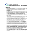
(Line Filter only) Since, except at the poles and the , the magnetic field during the
survey is at an angle, you can resolve the measured magnetic field intensity into
horizontal and vertical components 1.
Fv
Input vector
Vertical
component
vector
Inclination
Horizontal component vector
Fh
Calculating horizontal and
vertical components of a
vector in the spectral domain
The Horizontal component and Vertical component filters perform this operation,
outputting only horizontal or vertical component of the signal respectively. The
horizontal component is the 'along line' component.
These filters are currently available in the Line Filter tool. See "Vertical / Horizontal
Component filter" in Line Filtering (T31).
Horizontal and vertical components filters—parameters
Parameter
Description
Field Intensity,
Inclination,
Declination
See the general discussion of Reduction filters
(reference) for a description of the parameters used
by the filter.
Continuation filters (reference)
Parent topic:
INTREPID
spectral
domain
operations
reference (R14)
If you traversed the region at a greater height, you would be less likely to sense near
surface sources. Your data on regional sources would be less affected by this change.
If you traversed the region at a lower level, near surface sources would be more
intense. There could well also be noise that could obscure all sources.
Magnetic fields become weaker as distance increases. You can derive a formula to
transform the strength of a magnetic field sensed at one height to an estimate of the
field that you would sense at a different height. The continuation filters perform this
transformation.
For INTREPID tools reference about this topic, see:
"Continuation filter (GridFFT)" in Spectral domain grid filters tool (GridFFT) (T40)
"Upward Continuation filter" in Line Filtering (T31)
"Downward Continuation filter" in Line Filtering (T31)
In this section:
•
Continuation filters—parameters
•
Formula for continuation
•
Upward Continuation filter (reference)
•
Downward Continuation filter (reference)
•
Variable continuation filter (reference)
1. Blakely, Richard J., (1995) Potential Theory in Gravity and Magnetic Applications,
Cambridge University Press, p 328.
Library | Help | Top
© 2012 Intrepid Geophysics
| Back |
INTREPID User Manual
Library | Help | Top
INTREPID spectral domain operations reference (R14)
32
| Back |
Continuation filters—parameters
Parent topic:
Continuation
filters
(reference)
(Upward and downward continuation only)
See Variable continuation filter (reference) for Variable continuation parameters)
Parameter
Description
Level of Continuation
The increase or reduction in height at which you wish to 'view' the
data. If there is no separate control in your tool or language for
specifying the direction, specify a negative number for downward
continuation. Check the documentation of the tool you are using before
specifying a value.
Be sure that you do not specify a continuation level that:
•
Is below the land surface, or
•
Will result in excessive noise.
Degree of Rolloff
(Downward continuation in GridFFT only) Determines the sharpness of
the roll-off for high frequency damping. See Downward Continuation
filter (reference) for an explanation of damping.
Median Frequency of
Rolloff
(Downward continuation in GridFFT only) This frequency is the centre
of the roll-off region for high frequency damping. See Downward
Continuation filter (reference) for an explanation of damping.
Order of Stability
(Downward continuation in Line Filter only) This parameter is the
same as the Degree of Rolloff
Formula for continuation
Parent topic:
Continuation
filters
(reference)
Where:
d = damping factor (downward continuation only)
h = level of continuation (positive for up, negative for down)
w = frequency
F ( w ) = de
hw
Upward Continuation filter (reference)
Parent topic:
Continuation
filters
(reference)
Library | Help | Top
The Upward continuation filter recalculates the data as if you observed it at a greater
height. It allows you to see regional sources more clearly.
The level of continuation is relative to the acquisition height. For example, an
acquisition height of 50 m above ground level and an upward continuation of 100 m
will result in a profile height of 150 m above ground level.
For INTREPID tools reference about this topic, see:
"Continuation filter (GridFFT)" in Spectral domain grid filters tool (GridFFT) (T40)
"Upward Continuation filter" in Line Filtering (T31)
© 2012 Intrepid Geophysics
| Back |
INTREPID User Manual
Library | Help | Top
INTREPID spectral domain operations reference (R14)
33
| Back |
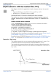
Downward Continuation filter (reference)
Parent topic:
Continuation
filters
(reference)
The Downward continuation filter recalculates the data as if you observed it at a
lower level. It allows you to see near surface sources more clearly. It may also
introduce noise to your data. If the continuation becomes unstable, INTREPID will
give you a warning message.
Downward continuation increases signal amplitudes at the higher frequency end of
the power spectrum (depending on the depth of continuation). The filter operation
can become unstable, especially with noisy data. There may be a 'blow-out' of power
at the higher frequencies.
For INTREPID tools reference about this topic, see:
"Continuation filter (GridFFT)" in Spectral domain grid filters tool (GridFFT) (T40)
"Downward Continuation filter" in Line Filtering (T31)
Damping of high frequencies
To stabilise downward continuation at high frequencies we use a damping factor.
This rolls off the higher frequencies using a low pass Butterworth filter (see
Butterworth filter (reference)). In the Butterworth filter, the Degree of rolloff is the
degree of the Butterworth filter and the Median frequency of rolloff is the Median
frequncy for the filter.
For INTREPID tools reference about this topic, see:
"Suggested values for Degree of Rolloff" in Spectral domain grid filters tool (GridFFT)
(T40)
"Downward Continuation filter" in Line Filtering (T31)
Variable continuation filter (reference)
Parent topic:
Continuation
filters
(reference)
This filter performs an upward or downward continuation of the magnetic field signal
to a new variable survey elevation (Drape Altitude) or to a constant survey Altitude..
To speed up this process you can classify possible heights into ranges (bins) and
calculate a standard correction for each bin. This way the process only needs to know
the bin to which the clearance of a data point belongs in order to add or subtract the
correction.
For INTREPID tools reference about this topic, see:
"Variable continuation filter" in Line Filtering (T31)
Variable continuation—parameters
Parameter
Description
Nominal Level of
Survey
Survey height to which you want to adjust the data (height at which survey
was meant to be flown according to the survey specifications).
Number of Bins to
Sort Heights
Number of bins for heights classification.
Nominal Height of
Bin (metres)
Specifying the height of each bin allows you further control on the number
of height values which will fall into each particular bin. The value of this
parameter would also depend upon the range of survey heights.
Cutoff Weight
Use this parameter to control the Butterworth filter, which dampens the
effect of the downward continuation. Without the filter, downward
continuation amplifies noise in the signal and becomes unstable for large
continuation distances.
Library | Help | Top
© 2012 Intrepid Geophysics
| Back |
INTREPID User Manual
Library | Help | Top
INTREPID spectral domain operations reference (R14)
34
| Back |
Filters for frequency ranges (pass filters)
Parent topic:
INTREPID
spectral
domain
operations
reference (R14)
You can use one or more of these to pass, reduce or reject selected frequency ranges.
In the Spectral Domain Grid Filters tool the filters all act upon the radially averaged
power spectrum, and their operation is therefore the same in all directions.
For INTREPID tools reference about this topic, see:
"Entering parameters for pass filters (interactive only)" in Spectral domain grid
filters tool (GridFFT) (T40)
"Low pass filter (GridFFT)" in Spectral domain grid filters tool (GridFFT) (T40)
"High pass filter (GridFFT)" in Spectral domain grid filters tool (GridFFT) (T40)
"Band pass filter (GridFFT)" in Spectral domain grid filters tool (GridFFT) (T40)
"Band Pass and Band Reject filters" in Line Filtering (T31)
"Low Pass filter" in Line Filtering (T31)
"High Pass filter" in Line Filtering (T31)
In this section:
•
Pass filters and Gibb's phenomenon (ringing)
•
Frequency units and the INTREPID filter tools
•
Low pass filter (reference)
•
High pass filter (reference)
•
Band pass filter (reference)
•
Cosine rolloff filter (reference)
•
Butterworth filter (reference)
•
Gauss filter (reference)
•
Matched filter (reference)
•
General symmetric filter (reference)
Pass filters and Gibb's phenomenon (ringing)
Parent topic:
Filters for
frequency
ranges (pass
filters)
Pass filters in their basic form are crude and can produce poor image quality
('ringing') after reverse spectral transform (Gibb's phenomenon). INTREPID
prevents ringing by automatically tapering the edges of the data passed by the filters
(i.e., include some of the rejected data starting at the cutoff frequency and tapering to
zero amplitude).
The Line Filter tool allows you to specify the length in data points of the tapering
range (rolloff window) for its pass filters using the Cutoff Rolloff Parameter.
The Spectral Domain Grid Filters tool pass filters automatically taper the edges
without your intervention.
Library | Help | Top
© 2012 Intrepid Geophysics
| Back |
INTREPID User Manual
Library | Help | Top
INTREPID spectral domain operations reference (R14)
35
| Back |
Frequency units and the INTREPID filter tools
Parent topic:
Filters for
frequency
ranges (pass
filters)
The Line Filter tool use cycles/km units for the cutoff frequencies. Power spectrum
graphs display frequency scale in cycles/km.
GridFFT enables you to select units, x 1000 multiples and frequency or wavelength.
See "Frequency, wavelength and distance unit multiples" in Spectral domain grid
filters tool (GridFFT) (T40).
The Old Spectral Domain Grid Filters tool uses cycles/m for cutoff frequencies in its
dialog boxes. If you use the power spectrum graph to assist you in choosing a cutoff
frequency for a filter, divide the frequency by 1000 to convert it to cycles/m before
specifying it in the filter dialog box. Power spectrum graphs display frequency scale
in cycles/km.
Low pass filter (reference)
Parent topic:
Filters for
frequency
ranges (pass
filters)
The Low Pass filter will retain the low frequency range of the power spectrum, using
a smooth curve to rolloff the data outside the cutoff frequency. You can use this filter
for removing high frequency noise and also near surface sources if required. The
filter is available for full tensor grids.
Here is an illustration of the effect of a Low Pass filter, showing the power spectrum
of the original data (the smooth descending curve) and the filter results (the curve
which drops to the horizontal axis and runs along it).
For INTREPID tools reference about this topic, see:
"Low pass filter (GridFFT)" in Spectral domain grid filters tool (GridFFT) (T40)
"Low Pass filter" in Line Filtering (T31)
Low pass filter—parameters
Parameter
Description
Cutoff frequency (or
wavelength)
Use this to specify the frequency below which INTREPID will retain
data.
Size of rolloff zone or
Cutoff rolloff parameter
(GridFFT and Line Filter tool only) Use this to specify the width of the
rolloff range around the cutoff frequency where INTREPID tapers the
energy of the data to 0. In GridFFT you can calculate and set this
automatically
Replace Trend in Output
(Line Filter tool only) Use this option to specify whether INTREPID
must replace any trend removed from the data before the filter process.
Library | Help | Top
© 2012 Intrepid Geophysics
| Back |
INTREPID User Manual
Library | Help | Top
INTREPID spectral domain operations reference (R14)
36
| Back |
High pass filter (reference)
Parent topic:
Filters for
frequency
ranges (pass
filters)
The High Pass filter will retain the high frequency range of the power spectrum,
using a smooth curve to rolloff the data outside the cutoff frequency. You can use this
filter for eliminating regional and deep sources, enabling you to see just the shallow
magnetic bodies. The filter is available for full tensor grids.
Here is an illustration of the effect of a High Pass filter, showing the power spectrum
of the original data (the upper curve) and the filter results (the lower curve).
For INTREPID tools reference about this topic, see:
"High pass filter (GridFFT)" in Spectral domain grid filters tool (GridFFT) (T40)
"High Pass filter" in Line Filtering (T31)
High pass filter—parameters
Parameter
Description
Cutoff frequency
(or wavelength)
Use this to specify the frequency above which INTREPID will retain
data.
Size of rolloff zone or
Cutoff rolloff parameter
(GridFFT and Line Filter tool only) Use this to specify the width of the
rolloff range around the cutoff frequency where INTREPID tapers the
energy of the data to 0. In GridFFT you can calculate and set this
automatically
Library | Help | Top
© 2012 Intrepid Geophysics
| Back |
INTREPID User Manual
Library | Help | Top
INTREPID spectral domain operations reference (R14)
37
| Back |
Band pass filter (reference)
Parent topic:
Filters for
frequency
ranges (pass
filters)
The band filter removes all data either within or outside a band (frequency range)
that you have specified. This can remove data associated with either near surface or
regional sources depending on how you specify the cutoff frequencies. You can use
this filter for eliminating high frequency noise and regional sources at the same time.
The filter is available for full tensor grids.
Here is an illustration of the effect of a 'pass' version of a band filter, showing the
power spectrum of the original data (the smooth downward curve) and the filter
results (the hump-shaped curve with low and high segments along the horizontal
axis).
For INTREPID tools reference about this topic, see:
"Band pass filter (GridFFT)" in Spectral domain grid filters tool (GridFFT) (T40)
"Band Pass and Band Reject filters" in Line Filtering (T31)
Library | Help | Top
© 2012 Intrepid Geophysics
| Back |
INTREPID User Manual
Library | Help | Top
INTREPID spectral domain operations reference (R14)
38
| Back |
Band pass filter—parameters
Parameter
Description
Low cutoff frequency
(or wavelength)
Use this to specify the frequency above which INTREPID will pass
or reject data.
High cutoff frequency
(or wavelength)
Use this to specify the frequency below which INTREPID will pass
or reject data.
Size of rolloff zone or
Cutoff rolloff parameter (low)
(GridFFT and Line Filter tool only) Use this to specify the width of
the rolloff zone outside the low cutoff frequency where INTREPID
tapers the energy of the data to 0. In GridFFT you can calculate and
set this automatically
Size of rolloff zone or
Cutoff rolloff parameter (high)
(GridFFT and Line Filter tool only) Use this to specify the width of
the rolloff zone outside the high cutoff frequency where INTREPID
tapers the energy of the data to 0. In GridFFT you can calculate and
set this automatically
Pass / Reject
Specify whether to remove the data within or outside the band that
you have specified. If you choose Pass, INTREPID retains the data
inside the band.
If you choose Reject, INTREPID retains the data outside the band.
The new Spectral Domain Grid Filters tool (GridFFT) does not have
this option and is always set to Pass.
The old Spectral Domain Grid Filters tool (OldGridFFT) has a pair
of option buttons for you to select.
The Line Filter tool has separate Band Pass and Band Reject menu
options.
Library | Help | Top
© 2012 Intrepid Geophysics
| Back |
INTREPID User Manual
Library | Help | Top
INTREPID spectral domain operations reference (R14)
39
| Back |
Cosine rolloff filter (reference)
Parent topic:
Filters for
frequency
ranges (pass
filters)
(Spectral Domain Grid Filters only) This filter will retain (pass) the low or high
frequency range of the power spectrum, tapering with a smooth cosine curve in a
rolloff range. You can specify the high and low frequency for the rolloff range, and the
degree of the cosine function. As the degree of the cosine function increases, the
transition between the passed and rejected sections of the spectrum becomes steeper.
Here is an illustration of the effect of a 'low pass' version of the Cosine Rolloff filter,
showing the power spectrum of the original data (upper curve) and the filter results
(lower curve).
Here is a formula for a 'low pass' Cosine Rolloff filter. Where
w0 = low frequency limit
w1 = high frequency limit
n = degree of cosine function
F( w) = 1
where w < w0
n
π w – w0
F ( w ) = ⎛⎝ cos ⎛⎝ --- ⎛⎝ -------------------⎞⎠ ⎞⎠ ⎞⎠
2 w1 – w0
where w0 < w < w1
F( w) = 0
where w > w1
Cosine rolloff filter—parameters
Low cutoff frequency Use this to specify the lower frequency limit of the rolloff
range below which INTREPID will totally pass or reject data.
High cutoff frequency Use this to specify the upper frequency limit of the rolloff
range above which INTREPID will totally pass or reject data.
Degree of cosine function Use this to specify the degree of the cosine function that
you require for the rolloff.
Pass / Reject Use these options to specify whether to retain the data above or below
the rolloff range.
If you choose Pass, INTREPID retains data below the rolloff range.
If you choose Reject, INTREPID retains data above the rolloff range.
Library | Help | Top
© 2012 Intrepid Geophysics
| Back |
INTREPID User Manual
Library | Help | Top
INTREPID spectral domain operations reference (R14)
40
| Back |
Butterworth filter (reference)
Parent topic:
Filters for
frequency
ranges (pass
filters)
(Spectral Domain Grid Filters only) This filter will retain (pass) one end of the power
spectrum according to a median frequency. You can use the Butterworth filter as a
general pass / reject filter by specifying your required cutoff value as the median
frequency.
To taper the data in the cutoff range INTREPID uses a smooth curve symmetrical
about the median frequency.
You can specify the degree of the filter. As the degree of the function increases, the
transition between the passed and rejected sections of the spectrum becomes steeper.
The Butterworth filter is tensor compatible.
Here is a formula for a Butterworth filter. Where
wc= Median frequency (cycles/m)
n= Degree of Butterworth Filter
'Low pass' version (retaining the low frequencies):
1
F ( w ) = ----------------------w n
⎛
1 + ⎝ ------⎞⎠
wc
'High pass' version (retaining the high frequencies):
w ⎞n
⎛ ----⎝ w c⎠
F ( w ) = ----------------------w n
1 + ⎛⎝ ------⎞⎠
wc
w-⎞ n
⎛ ----⎝ w c⎠
F ( w ) = -------------------w n
1e ⎛ ------⎞
⎝ w c⎠
Butterworth filter—parameters
Central frequency (central wavenumber) Use this to specify the cutoff (median)
frequency for the filter. This is will be the central frequency in the rolloff range.
Rolloff Degree Use this to specify the rolloff degree of the Butterworth filter that
you require.
Pass / Reject Use these options to specify whether to retain the data above or below
the median frequency.
If you choose Pass, INTREPID retains data below the median frequency.
If you choose Reject, INTREPID retains data above the median frequency.
Library | Help | Top
© 2012 Intrepid Geophysics
| Back |
INTREPID User Manual
Library | Help | Top
INTREPID spectral domain operations reference (R14)
41
| Back |
Gauss filter (reference)
Parent topic:
Filters for
frequency
ranges (pass
filters)
(Spectral Domain Grid Filters only) This filter will retain (pass) the low or high
frequency range of the power spectrum using a smooth Gauss curve in a rolloff range.
The specified value for the power spectrum standard deviation determines the
steepness of the filter curve.
A further use of a Gaussian filter is made for derivative grids when they are to be
passed into the Euler tool. BRGM and others have noted that the Euler equations are
very vulnerable to noise and that a simple Gausian filter around the Nyquist
frequency is a simple way of adding extra protection from noise.
Here is a formula for a Gauss filter
σ = standard deviation
'Low pass' (retaining the low frequencies):
F( w) = e
w
– 0.5 ⎛ ----⎞
⎝ σ⎠
2
'High pass' (retaining the low frequencies):
F( w) = e
w 2
0.5 ⎛ ----⎞
⎝ σ⎠
Gauss filter—parameters
The spectral filter works by applying a roll-off around the central frequency in the
grid dataset. All wavenumbers are divided by the standard deviation parameter
and the Fourier coefficients are scaled by the exponential term as shown above.
This contrasts with a spatial Gaussian filter that is designed to be centered around a
particular wave-length and a roll-off to either side.
Standard deviation Use this to specify the standard deviation for INTREPID to use
in the filter.
Pass / Reject Use these options to specify whether to retain the data above or below
the rolloff range.
If you choose Pass, INTREPID retains data below the rolloff range.
If you choose Reject, INTREPID retains data above the rolloff range.
Library | Help | Top
© 2012 Intrepid Geophysics
| Back |
INTREPID User Manual
Library | Help | Top
INTREPID spectral domain operations reference (R14)
42
| Back |
Matched filter (reference)
Parent topic:
Filters for
frequency
ranges (pass
filters)
(Spectral Domain Grid Filters only) The matched filter extracts data that
characterises major sources. It is sometimes called a depth slice filter. The
technique is as follows
1
Identify sections of the power spectrum that characterise the major regional
source and the near surface data.
2
Draw a straight line on the power spectrum characterising each type of data. One
line will be approximately parallel to the low frequency part of the curve and the
other approximately parallel to the high frequency part.
Process the dataset so that the regional data is mapped onto a regional line and
the near surface data is removed.
The method leads to techniques for identifying and extracting data from regional
3
sources at specific depth ranges. Cowan and Cowan1 call this Separation Filtering.
It forms the basis of the World Geoscience Depth Slicing technique2.
Here is an illustration of the effect of a Matched filter, showing the power spectrum of
the original data (upper curve) and the filter results (lower curve).
Matched filter—parameters
b, h, (near surface) and B, H (regional)
B = The slope of the low frequency line (regional)
H = The vertical (energy) axis intercept for the low frequency line
b = The slope of the high frequency line (near surface)
h = The vertical (energy) axis intercept for the high frequency line
1. Cowan, D.R. and Cowan, S., (1993) Separation Filtering Applied to Aeromagnetic Data,
Exploration Geophysics 24, 429–436
2.Norman, C., (1993), New developments in the aeromagnetic technique for
sedimentary basin evaluation, ASEG Preview, Feb 1993.
Library | Help | Top
© 2012 Intrepid Geophysics
| Back |
INTREPID User Manual
Library | Help | Top
INTREPID spectral domain operations reference (R14)
43
| Back |
General symmetric filter (reference)
Parent topic:
Filters for
frequency
ranges (pass
filters)
(Spectral Domain Grid Filters only) This filter enables you to divide the power
spectrum into a number of segments and pass, reduce or reject the data from each
segment. It is a 'design your own' filter.
INTREPID will divide the power spectrum into a set of segments of the length you
specify. The starting frequency is 0 for the purposes of this division. It will assign a
coefficient to each segment and multiply the data within the segment by its
coefficient. A coefficient of 1 causes INTREPID to pass the data as it is; a coefficient
of 0 causes it to reject the data; a coefficient between 0 and 1 will reduce the energy of
the data before passing it.
Examples:
•
You could define a low pass filter to .8 with a rolloff using the following settings:
Frequency increment = 0.2
Filter coefficients = 1, 1, 1, 1, .75, .5, .2, 0
•
You could define a band pass filter for the interval .4 to .6 using the following
settings:
Frequency increment = 0.2
Filter coefficients = 0, 0, 1, 1, 0, 0, 0, 0
General symmetric filter—parameters
Frequency increment (Wavenumber Increment) Use this to specify the length
(in frequency units) of one segment.
Filter Coefficients Specify the 8 coefficients after the Frequency Increment. Enter
one coefficient for each segment. Separate each pair of coefficients by a space.
Library | Help | Top
© 2012 Intrepid Geophysics
| Back |
INTREPID User Manual
Library | Help | Top
INTREPID spectral domain operations reference (R14)
44
| Back |
Directional Filters
Parent topic:
INTREPID
spectral
domain
operations
reference (R14)
(Spectral Domain Grid Filters only) You can use the directional filters to remove or
enhance features that are aligned in a particular direction. Directional features in
the spatial domain will have a corresponding effect in the sector of the spectral
domain corresponding to that direction. In the illustration below, a corrugation in the
spatial domain causes an effect in the sector of the spectral domain at right angles to
the line of the corrugation.
Y
Fy
X
Fx
Directional Feature in the
spatial domain
(e.g., corrugation)
Sectors of the spectral domain which show
the effect of the directional feature
In this section:
•
Directional pass filter (reference)
•
Directional cosine filter (reference)
Directional pass filter (reference)
Parent topic:
Directional
Filters
The Directional Pass filter will totally reject or accept the data within the sector of
the spectral domain that you specify. Note that pass filters are crude and may
produce poor image quality ('ringing') after reverse spectral transform. We
recommend that you normally use the Directional Cosine filter for this purpose (See
Directional cosine filter (reference)).
Directional pass filter—parameters
Low cutoff angle Use this to specify the angle (in degrees) for the lower limit of the
pass / reject range in this text box. Measure the angle clockwise with 0°
corresponding to North.
High cutoff angle Use this to specify the angle (in degrees) for the upper limit of the
pass / reject range in this text box. Measure the angle clockwise with 0°
corresponding to North.
Pass / Reject Select Pass to pass the data that falls between the angles you have
specified and reject the rest of the data. Select Reject to reject the data that falls
between the angles you have specified and pass the rest of the data.
Library | Help | Top
© 2012 Intrepid Geophysics
| Back |
INTREPID User Manual
Library | Help | Top
INTREPID spectral domain operations reference (R14)
45
| Back |
Directional cosine filter (reference)
Parent topic:
Directional
Filters
The Directional Cosine filter will pass or reject data in the direction and angular
width that you specify. It will create a smooth curve from pass to reject in the data
surface at a rate depending on the rolloff degree specified. This elimination of sudden
changes in the data prevents 'ringing' in the image when INTREPID transforms the
data back to the spatial domain.
Directional cosine filter—parameters
Azimuth Use this to specify the direction (in degrees) around which you require the
filter to pass or reject data. The azimuth is measured clockwise from North with
0° corresponding to North.
Azimuthal Half Width Use this to specify the half angle (in degrees) within which
the filter will pass or reject data.
Rolloff Degree Use this to specify the degree of rolloff that you require for the cosine
function. The normal degree range is between 0.5 and 2. Lower rolloff degrees
result in a steeper 'ridge'Azimuthal Half Width Use this to specify the half
angle (in degrees) within which the filter will pass or reject the data.
Pass / Reject Select Pass to pass data around the direction you have specified and
reject the rest of the data. Select Reject to reject data around the direction you
have specified and pass the rest of the data.
Complex filters
Parent topic:
INTREPID
spectral
domain
operations
reference (R14)
Library | Help | Top
(Spectral Domain Grid Filters only) The Complex filters are commonly used special
combinations of filters.
In this section:
•
Pseudo gravity transformation (reference)
•
Susceptibility filter (reference)
•
Decorrugation filter (reference)
•
Apparent density filter (reference)
© 2012 Intrepid Geophysics
| Back |
INTREPID User Manual
Library | Help | Top
INTREPID spectral domain operations reference (R14)
46
| Back |
Pseudo gravity transformation (reference)
Parent topic:
Complex filters
Gravity behaves similarly to magnetic fields as the distance from the source
increases. Using the magnetic field, you can estimate the gravity anomaly that would
be observed if the magnetisation distribution were replaced with an identical density
distribution. This transformation can be useful for determining the edges of source
bodies, and comparing gravity and magnetic data to distinguish between the effects of
different source rock types.
The transformation of magnetic anomaly into pseudogravity is done through
Poisson's relation. You need to specify the ratio of susceptibility contrast to average
density contrast as a parameter for the transformation.
Here is a formula for a pseudo gravity filter. It assumes that you require the gravity
field at the same height as the magnetic readings. Where
G = Universal Gravitational Constant
T = Geomagnetic field intensity
p = contrast ratio
Δ = height separation
r = radial distance from origin of spectral domain
Δhr
Gp e
F ( r ) = ------- -----------4T r
Pseudo gravity transformation—parameters
Inclination, Declination, Field Intensity See The geomagnetic reference field in
INTREPID (R15) for information about these parameters.
Susceptibility / Density Contrast Ratio See the discussion immediately above for
an explanation of this parameter. If you are only interested in the relative
distribution of gravity data, set this to 1. To obtain gravity in SI units, enter all
values in SI units.
Altitude Separation Use this to specify the difference (in m) between the height of
the magnetic reading and the desired apparent height of the gravity field values
calculated.
Library | Help | Top
© 2012 Intrepid Geophysics
| Back |
INTREPID User Manual
Library | Help | Top
INTREPID spectral domain operations reference (R14)
47
| Back |
Susceptibility filter (reference)
Parent topic:
Complex filters
This is a commonly used composite of Downward Continuation, Reduction to the Pole
and Prism Map filters. This filter indicates the susceptibility of the land surveyed to
magnetic induction. INTREPID applies the Susceptibility filter to a vertical prism of
earth with a square cross section. See Continuation filters (reference) and Reduction
filters (reference) for more details about these components.
Here is an illustration of the effect of the Susceptibility filter, showing the power
spectrum of the original data (lower curve at left end) and the filter results (upper
curve at left end).
Susceptibility filter—parameters
Inclination, Declination, Field Intensity See The geomagnetic reference field in
INTREPID (R15) for information about these parameters.
Depth of continuation Use this to specify the depth (in metres) below the sensor at
which you wish to 'view' the data.
Latitude for amplitude limit Use this to specify the latitude below which you wish
to adjust the phase only of the data. See Reduction to the Pole (reference) for a
detailed description of this parameter
Dimension of prism Use this to specify the side (in metres) of the square prism
cross section.
Note - if the susceptibility spectral filter window displays 'stripes' or 'banding effects',
this usually means the dimension of the prism is set too high. In this case decrease
that parameter and the stripes will retreat to the top and bottom ends of the
graphical filter response, and eventually disappear. You'll also get an output grid that
appears less smoothed.
The output from the magnetic susceptibility complex filter are in S.I. units.
Library | Help | Top
© 2012 Intrepid Geophysics
| Back |
INTREPID User Manual
Library | Help | Top
INTREPID spectral domain operations reference (R14)
48
| Back |
Decorrugation filter (reference)
Parent topic:
Complex filters
Magnetic surveys carried out using an aircraft involve the aircraft alternately
travelling in opposite directions across the area to be surveyed. Sometimes the
direction of traverse subtly affects the Z data. After the gridding process, if you are
viewing the results of the survey as an grid, you can see the traverse patterns as
'corrugations'.
The Decorrugation filter can detect and remove these corrugations from the data.
Decorrugation uses a combination of Butterworth and Directional Cosine filters (See
Butterworth filter (reference) and Directional cosine filter (reference) for a detailed
description.
We provide a separate Decorrugation tool for decorrugation in the survey levelling
process. This tool uses Naudy and/or Fuller filters directly on the spatial data,
whereas the decorrugation filter described here in the Grid Filters tool works on the
data in the spectral domain. You can use the Decorrugation tool instead of the
spectral domain decorrugation process if you wish. See Decorrugation (T32) for a full
description of Decorrugation.
Decorrugation filter—parameters
Line Spacing Use this to specify the average distance between the traverse lines in
the original survey.
Direction Along Striping from North Use this to specify the approximate
direction of the corrugations. This is usually the same as the direction of the
traverse lines in the original survey. Specify the direction as a number between 0
and 180 representing the bearing in degrees. 0° and 180° indicate North–South
bearing and 90° indicates East–West.
If you do not know the direction of the traverse lines in the original survey, you
can use the Gridding tool or Flight Path Editor modules to report the average
strike (See "Nominal Bearing" in Old Gridding (T22) and "Line data validation"
in Flight Path Editor (T19) for instructions).
Library | Help | Top
© 2012 Intrepid Geophysics
| Back |
INTREPID User Manual
Library | Help | Top
INTREPID spectral domain operations reference (R14)
49
| Back |
Apparent density filter (reference)
Parent topic:
Complex filters
If you are working with gravity data, you can use the Apparent Density filter to
estimate the density of the source. The Apparent Density model assumes that the
source is contained in a uniform layer of earth. You can specify the layer thickness
for the model.
We recommend that you also apply a Downward Continuation filter to the data before
using the Apparent Density filter. This filter should transform your view of the data
to the top surface of the source (i.e., the Continuation level should be equal to the
distance from the sensor to the assumed top surface of the source.
Here is an illustration of the effects of an Apparent Density filter, showing the power
spectrum of the original data (upper curve) and the filter results (lower curve).
Apparent density filter—parameters
Thickness of the Earth Model Use this to specify the thickness of the earth layer
that you are assuming contains the source.
Vertical Integral filter (reference)
Parent topic:
INTREPID
spectral
domain
operations
reference (R14)
This filter integrates from the observation elevation up to infinity. In principle it is
the reverse operation of the first vertical derivative.
The Altitude Difference parameter is the altitude above the ground at which the data
was collected. INTREPID will use this parameter to downward continue the data to
the ground before performing the vertical integration, so that the resulting
integration will more closely resemble a ground based survey result.
One use of the vertical integral filter is in combination with a gradient filter, such as
the Analytic Signal, to convert the data back to the original ‘non-gradient’ units.
Library | Help | Top
© 2012 Intrepid Geophysics
| Back |