1
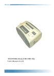
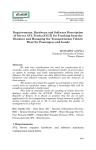
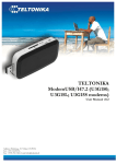
TELTONIKA ModemCOM (TMC-10x)
User Manual V2.1.1.18
TABLE OF CONTENTS
ATTENTION! .............................................................................................................................................3
LEGAL NOTICE........................................................................................................................................3
INTRODUCTION......................................................................................................................................4
1. PACKAGE CONTENTS......................................................................................................................5
2. TECHNICAL SPECIFICATIONS......................................................................................................6
2.1. Data transferring...............................................................................................................................6
2.2. Mechanical specifications ................................................................................................................6
2.3. Electrical and operating specifications ..........................................................................................7
2.4. Indication ...........................................................................................................................................7
2.5. Connectors.........................................................................................................................................8
2.5.1. Pin outs of DB9(COM) connector ........................................................................................8
3. MODEM SETUP ....................................................................................................................................9
3.1. Connecting to PC .............................................................................................................................9
3.2. Installation of “Modem Control Tool”.........................................................................................9
3.3. Setting up an Internet connection............................................................................................... 12
3.4. Sending Short Text Messages (SMS) .......................................................................................... 15
3.5. Changing of security settings ....................................................................................................... 17
3.6. Settings of program language....................................................................................................... 18
3.7. Choice of GSM operators ............................................................................................................ 19
3.8. Other functions of program......................................................................................................... 20
4. ACRONYMS......................................................................................................................................... 21
TECHNICAL SUPPORT ....................................................................................................................... 22
2
ATTENTION!
Do not rip the device. Do not touch the device if the device
block is broken or his connecting wires are without isolation
All wireless devices for data transferring may be susceptible to
interference, which could affect performance.
Only qualified personnel may install or repair this product.
Your device is not water-resistant. Keep it dry.
LEGAL NOTICE
Copyright © 2006 TELTONIKA Ltd.
All rights reserved. Reproduction, transfer, distribution or storage of part or all of the contents in this
document in any form without the prior written permission of TELTONIKA Ltd is prohibited.
Other product and company names mentioned herein may be trademarks or trade names of their
respective owners.
3
INTRODUCTION
This document will provide you with the instructions how to install and use “ModemCOM“
and its software.
“ModemCOM“ is a device designed for data transmission via GSM Network. The design of this
modem enables the connection to your PC through COM interface. Once the modem is connected to
the PC, you can get access to the Internet via one of the data transmission type the GSM is supported.
“ModemCOM“ supports the following data-bearers: EDGE, GPRS, CSD, CSF, HSCSD and SMS.
4
1. PACKAGE CONTENTS
“ModemCOM“ is supplied to clients in carton with all contents, which are needed for
connection to PC and normal work.
1)
2)
3)
4)
5)
6)
Carton;
“ModemCOM“ modem;
RS232 connecting cable;
CD with User’s Guide, drivers and Software;
External GSM antenna (just upon special orders);
AC/DC mains adapter.
Notice: the producer does not provide a SIM card among other items of a package, which is necessary
for connection to GSM Network! You can obtain a SIM card from your local GSM service provider!
If any of the components is missing please contact your local distributor.
5
2. TECHNICAL SPECIFICATIONS
2.1. Data transferring
„ModemCOM“ supports below write bearers of GSM Network. Which data type is used
depends on GSM operator and data transfer capacity in the chosen GSM Network.
• EDGE class 6 (class B);
• GPRS class 10 (class B);
• HSCSD;
• CSD;
• CSF;
• SMS textual messages.
2.2. Mechanical specifications
„ModemCOM“ housing is made of plastic. It is light and suitable for using in home, office or
industrial environment. Rubber covers a part of case. The external dimensions and measures of the unit
are shown in picture 1.
Picture 1. An external look and measures of the device
6
2.3. Electrical and operating specifications
Acceptable voltage range is 6 - 12 V DC. 9 V is a nominal value.
The PC the “ModemCOM“ modem is connected to must have a RS232 (COM) interface.
Note: The device must be powered with AC/DC adapter provided by manufacturer.
Electrical parameters of the device are shown in the Table 1.
Table 1. Electrical parameters of the device
Parameter
Min
Typical
Max
Meas. Units
Power Supply Voltage
+6
+9
+12
V
Average Power consumption
360
mW
Maximum Power consumption 1
8400
mW
1
Does not last more than 1.2 ms
Operating conditions and other parameters are shown in Table 2.
Table 2. Operating conditions and the like
Parameter
Min
Weight
Typical
Max
85 ± 10
Meas. Units
g
Recommended operating
temperature
+15
+35
ºC
Marginal operating temperature
-35
+75
ºC
Storage temperature
-40
+85
ºC
Notice: if the settings outreach the characteristics given above the device can be damaged!
2.4. Indication
“ModemCOM“ has 2 LEDs for indication. They are located at the top part of the device. Due
to these indicating LEDs we can determine in which mode is the device operating, are there any
shortcuts in its functionality or not. The indication status of the modem is given in the Table 3.
Table 3. Description of modem status
“Power” is on
Power supply is connected
“Status” is green and blinking
Modem is powering up
“Status” is green
The device is ready to use
No SIM card inside, no PIN code entered or any
“Status” is yellow and blinking
possibility to connect to the GSM Network
The device has successfully connected to the
“Status” is yellow
Network for data transfer
7
2.5. Connectors
RS232 connector
SIM card slot
DC Power supply
Picture 2. Back view of “ModemCOM“
Connectors:
• DB9 female for connection to the device;
• 3,5 mm/1,35 mm power supply connector;
• SIM card slot.
2.5.1. Pin outs of DB9(COM) connector
Pin outs of DB9 connector are provided in Picture 3.
Picture 3. Pin outs of “ModemCOM” and direction of the signals
8
3. MODEM SETUP
3.1. Connecting to PC
1)
2)
3)
4)
5)
6)
7)
Turn off your PC;
Insert the SIM card into modem. Follow the instructions on the device sticker. Make
sure, the SIM card is pushed inside till it fixes;
Plug DB9 connector of the serial (RS232) cable into the modem;
Plug another end of the serial cable to one of the COM ports of PC;
Plug in the AC/DC adapter to power supply socket of “ModemCOM“;
Plug in the AC/DC adapter to power supply network;
Turn on your PC.
3.2. Installation of “Modem Control Tool”
1. Open the “ModemCOM“ pack and take only
the CD and Plug the CD into the PC CD Drive;
2. Wait till the system displays the screen “Select
Setup Language” choose your language and press
„Ok“ button. Following TELTONIKA Home
screen will appear;
3. Click “Install” button. Following screen will appear.
9
4.
Press “Next” button in the opened
screen. A second “Modem Control tool
Setup” dialog box will appear;
5. Select „Complete“ button and
„Next“, following screen will appear;
click
6.
Program automatically will choose COM
port where modem is connected you must just
press “Next” in the opened dialog;
10
7.
Press “Install” in the opened dialog;
8. “Hardware Installation” dialog box
will appear, then press “Continue anyway”
button in the dialog box.
Using “Windows 2000” OS, all “Modem
Control Tool” installation steps are
identical, with exception of appearance of
“Digital Signature Not Found” dialog
box, where “Yes” button should be clicked;
9.
Enter dial-up connection parameters:
“ISP Name”, “Phone number”, “APN”,
“User Name” and “Password”.
“ISP Name” and “Phone number” by default
is Internet and *99# and press “Next” in the
opened dialog;
Note: APN, user name and password ask your
GSM operator!
11
10. Press “Finish” in the opened dialog box
“Modem Control tool Setup”. The installation
is done;
3.3. Setting up an Internet connection
In this chapter we will provide you with general information and procedures necessary for setting
up an Internet connection in your PC. When using “Modem Control Tool”, the Internet connection
settings are determined automatically.
Before you begin make sure that:
•
You have a GSM SIM card with activated data transfer service;
•
“ModemCOM“ is ready to work – SIM card is pushed in, the device is
correctly connected to the PC, the drivers are properly installed;
•
TCP/IP protocol is installed on your PC.
Then you using “ModemCOM“ you can get access to the Internet via one of this data
transmission types:
• GPRS/EDGE packet data transfer. In this case you have to know APN,
User name and Password;
• CSD/HSCSD data transfer. You have to know a phone number of a dial-up
server.
If GPRS/EDGE data transfer is used, you have to set up an APN, if needed, user name and
password.
1) Start “Modem Control Tool”. If needed the PIN code, enter it;
2) Press “Program Settings” button:
3)
4)
5)
6)
7)
Select “GPRS Settings”;
Enter the APN;
Enter the ISP and Phone number [*99#], if they not entered automatically;
If needed, enter the User name and User password;
Press “Update Data”.
12
Note: APN, user name and password ask your GSM operator!
Getting connected to the Internet:
1. The dial-up connections being set, start “Modem Control Tool” program. The program
can be started also from the PC desktop (or “Start → Programs → Modem Control Tool →
Modem Control Tool”) while clicking on the shortcut. When the shortcut will be clicked,
“Modem Control Tool” dialog box will be opened. If PIN control code is set on your SIM
card, the program will ask you to enter PIN code;
2. The program should automatically detect a connected modem. If you start the program
before connect modem, you have to wait till modem will be ready to work. If the program
not detected your modem, press “Program Settings → Modem Settings → Autodetect
Modem” if device not detected anyway, check connection, to be sure that the port is
chosen correctly and press “Detect Modem on COM* Port”;
13
3. To connect to the Internet, press “Connect To Internet Using Modem” button:
4. The modem starts connecting to Internet after clicking on this button. Then the modem
connected to Internet, you will see message “Connected To Internet Using Modem.”;
5. Exit the program, press “Exit Program” button:
If you can not connect the Internet using Internet Explorer after using Modem fallow this
steps, press “Start → Settings → Control Panel → Internet Options”. Select the box “Connections” in the
appeared dialogue box “Internet Properties”.
14
Select dial-up pictogram In the “Dial-up and Virtual Private Network settings” square and press
“Set Default” button, then chose “Always dial my default connection” and press “Apply” and
“OK” buttons. Now try to connect to Internet again.
3.4. Sending Short Text Messages (SMS)
1. Using “ModemCOM“ it is possible to send and receive short text messages (SMS). Before
start using that “ModemCOM“ function it is obligatory to disconnect from the Internet.
This will be performed while clicking on “Disconnect From Internet” button;
2. Before sending SMS messages you have to check number of messages sending center. Press
“Program Settings” and “SMS Settings”. In the window of “SMS Settings” should be
automatically entered number of messages sending center if it not entered, enter it. This
Number you can ask your GSM operators;
15
3. Press “Short Messages Service” button on “Modem Control Tool” window for writing
and reading of SMS messages:
4. In the window “Create New SMS” you can write your short SMS messages. In the “Type
Phone Number “ square enter phone number with code of country you will send without
“+” symbol. Below in the “Place Your Text Below” square write your short SMS
message. How many symbols left you can see in the right side above SMS text square. Then
your short SMS message is over press “Send”. And wait for the message: “Message Sent
Successful” or “Message Was Not Sent”;
5. All so you can read your incoming, sent and unsent short SMS messages. Press “Short
Messages Service” and “Unread” button. In the window will open, will be list of all
unread messages. Then you select one of the messages, on the right side of windows
appears the selected SMS message’s text. All readied short SMS messages goes to menu
“Read”. To delete selected messages press “Delete SMS”, to delete more than one SMS
press and hold “Shift” button on the keyboard and select SMS you want to delete. To
update messages windows press “Update SMS” button.
16
3.5. Changing of security settings
For SIM security a unique PIN (Personal Identification Number) is used. Before starting using
GSM network services, it is necessary to enter a PIN code. “ModemCOM“ supports two main GSM
security modes: “PIN Request Disable”, “PIN Request Enable”. When “PIN Request Disable”
is chosen, PIN code has to be entered just once and this will not be required further on while turning
the device on. If the mode “Enable” is chosen, the PIN code will be required each time the modem is
turned on.
“Modem Control Tool” program is used for changing security settings.
PIN control code switching off:
1)
2)
3)
4)
5)
Start “Modem Control Tool”;
Select “Program Settings”;
Select “Security Settings”;
Select “PIN Request Disable”;
Press “Update Date”;
17
6) On the window will open enter PIN code and press “OK”.
PIN control code switching on:
1)
2)
3)
4)
5)
Start “Modem Control Tool”;
Select “Program Settings”;
Select “Security Settings”;
Select “PIN Request Enable”;
Press “Update Date”;
6) On the window will open enter PIN code and press “OK”.
3.6. Settings of program language
On press “Program Settings” and “Language”, you can change the program language:
18
Note: by default program language is English
3.7. Choice of GSM operators
Choose “Program Settings → GSM Oper. Selection”. The “GSM Operator Selection”
screen will appear
Then you will click “Get GSM Operators List” button the program will show all available GSM
operators. Click “Select Available GSM Operator” button after you choose your desirable operator
and the desirable operator will be chosen.
19
3.8. Other functions of program
On press “Modem Information”:
You will see information about your using modem: developer, model, IMEI, operator and supplement
information.
On press: “About This Program”:
There will show version of using program, developer address, telephone number, e-mail and developer
Internet address.
On right side of “Modem Control Tool” window is GSM signal level indicator:
If you using modem, make attention to the signal level indicator. The signal level must be high for
stability connection. If signal level is low the Internet reception can be not stability. For that
recommended modem or his external antenna put into more open place.
.
20
4. ACRONYMS
AC/DC
Alternating Current/Direct Current
APN
Access Point Name
CSD
Circuit Switched Data
CSF
Circuit Switched Fax
GPRS
General Packet Radio Service
GSM
Global System for Mobile communications
IMEI
International Mobile Equipment Identity
ISP
Internet Service Provider
LED
Light Emitting Diode
OS
Operating System
PDP
Packet Data Protocol
PIN
Personal Identification Number
SIM
Subscriber Identity Module
SMS
Short Message Service
TCP/IP
Transmission Control Protocol/Internet Protocol
DCD
Data Carrier Detect
RxD
Received data
TxD
Transmitted Data
DTR
Data Terminal Ready
SG
Signal Ground
DSR
Data Set Ready
RTS
Request to Send
CTS
Clear to Send
RI
Ring Indicator
HSCSD
High speed Circuit Switched Data
EDGE
Enhanced Data rates for GSM Evolution
21
TECHNICAL SUPPORT
This sign on the package means that it is necessary to read a User Manual, which is
on the CD before you start using the device.
This sign on the package means, that used electronic and electric equipment should
be stored separately.
If you have faced some problems using the device, which you are not able to solve by yourself,
you are always welcome to address our technical support department by e-mail [email protected] .
We will be very glad to help you.
H
H
22