1
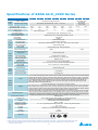
Specifications of ASDA A2-E_220V Series
Phase / Voltage
400W
750W
04
07
Three-phase / Single-phase 220VAC
Permissible Voltage Range
Three-phase / Single-phase 200 ~ 230VAC , -15%~10%
ASDA A2-E Series
Power
Supply
Input Current (3PH) Unit: Arms
Input Current (1PH) Unit: Arms
Continuous Output Current Unit: Arms
Cooling Method
Encoder Resolution
(Servo Drive Resolution)
Control of Main Circuit
Tuning Modes
Dynamic Brake
Command Source
Position
Smoothing Strategy
Control
Electronic Gear
Torque Limit Operation
Mode
Feed Forward
(CSP)
Compensation
Speed Control Range*1
Speed
Control
Mode
(CSV)
Torque
Control
Mode
(CST)
Digital
0.39
0.69
0.9
200W
02
1.11
1.86
1.92
3.22
1.55
2.6
Natural Air Circulation
3.66
6.78
5.1
1kW
10
4.68
8.88
7.3
1.5kW
15
5.9
10.3
8.3
Fan Cooling
SVPWM (Space Vector Pulse Width Modulation) Control
Auto / Manual
Built-in
External analog signal
Low-pass and P-curve filter
Electronic gear N/M multiple N: 1 ~ 32767, M: 1 : 32767 (1/50 < N/M < 25600)
External analog signal
External analog signal / Internal parameters
1:5000
1:3000
External analog signal
Smoothing Strategy
Torque Limit Operation
Frequency Response
Characteristic
Low-pass and S-curve filter
Set by parameters or via analog input
Speed Accuracy
(at rated rotation speed)*2
0.01 % or less at 0 to 100 % load fluctuation
0.01 % or less at 0℃ to 50℃ ambient temperature fluctuation
Feed Forward
Compensation
0.01 % or less at ±10 % power fluctuation
Command Source
External analog signal
Smoothing Strategy
Low-pass filter
Speed Limit Operation
Via analog input
Inputs
Inputs/
Outputs
Protective Functions
Communication Interface
Installation Site
Altitude
Atmospheric Pressure
Operating Temperature
Storage Temperature
Humidity
Vibration
IP Rating
Power System
2kW
3kW
20
30
Three-phase 220VAC
Three-phase
200 ~ 230VAC ,
-15% ~ 10%
8.76
9.83
13.4
19.4
Incremental type: 20-bit;Absolute type: 17-bit
Command Source External
Analog Signal
Outputs
Environment
100W
01
Maximum 1 kHz
Servo on, Reset, Gain switching, Pulse clear, Zero speed CLAMP, Command input reverse control, Command triggered,
Speed/Torque limit enabled, Position command selection, Motor stop, Speed position selection, Position / Speed mode
switching, Speed / Torque mode switching, Torque / Position mode switching, PT / PR command switching, Emergency
stop, Forward / Reverse inhibit limit, Reference “Home” sensor, Forward / Reverse operation torque limit, Move to
“Home”, Electronic Cam (E-Cam), Forward / Reverse JOG input, Event trigger PR command, Electronic gear ratio
(Numerator) selection and Pulse inhibit input
Encoder signal output (A, B, Z Line Driver and Z Open Collector )
Servo ready, Servo on, At Zero speed, At Speed reached, At Positioning completed, At Torques limit, Servo alarm (Servo
fault) activated, Electromagnetic brake control, Homing completed, Output overload warning, Servo warning activated,
Position command overflow, Forward / Reverse software limit, Internal position command completed, Capture operation
completed output., Motion control completed output., Master position of E-Cam (Electronic Cam)
Overcurrent, Overvoltage, Undervoltage, Motor overheated, Regeneration error, Overload, Overspeed, Abnormal pulse
control command, Excessive deviation, Encoder error, Adjustment error, Emergency stop activated, Reverse/ Forward
limit switch error, Position excessive deviation of full-close control loop, Serial communication error, Input power phase
loss, Serial communication time out, short circuit protection of U, V, W, and CN1, CN2, CN3 terminals
USB / EtherCAT
Indoor location (free from direct sunlight), no corrosive liquid and gas
(far away from oil mist, flammable gas, dust)
Altitude 1000 m or lower above sea level
86kPa ~ 106kPa
0℃ ~ 55℃ (If operating temperature is above 45℃ , forced cooling will be required)
-20℃ ~ 65℃
0 ~ 90% RH (non-condensing)
9.80665 m/s2 (1 G) less than 20 Hz, 5.88 m/s2 (0.6 G) 20 to 50 Hz
IP20
TN System*3
IEC/EN 61800-5-1, UL 508C, C-tick
Approvals
Footnote:
*1 Rated rotation speed: When full load, speed ratio is defined as the minimum speed (the motor will not pause).
*2 When command is rated rotation speed, the speed fluctuation rate is defined as: (Empty load rotation speed – Full load rotation speed) / Rated rotation speed
*3 TN system: A power distribution system having one point directly earthed, the exposed conductive parts of the installation being connected to that point
by a protective earth conductor.
2