1
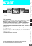
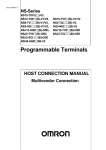
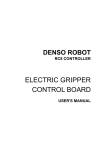
For devices and components connected to the PT that affect safety, use appropriate products meeting the required safety level and safety category. System safety and the appropriate safety category must be evaluated for the entire system. Consult a certified third-party organization to determine the appropriate safety category. It is the user's responsibility to ensure that system safety adheres to relevant standards. NSH5 Series NSH5-SQ@10B-V2 Programmable Terminal INSTRUCTION SHEET Thank you for purchasing a NSH5-series Programmable Terminal. Please confirm that you have received the correct product, and then read this instruction sheet and be sure you understand the contents completely before attempting to use the product. For detailed information on specifications and usage, refer to the PT and Support Software manuals. Please retain this instruction sheet for future reference. RE S RESET ET SET RE RUN F6 F7 F8 Connect the emergency stop switch and enabling switch on the PT so that they function according to stop category 0 or 1 described in IEC/EN 60204-1. There are two types of switches on the PT, a red one for use as an emergency stop switch, and a gray one for use as a stop switch. Use each of these for its intended purpose. ⋅ When using a PT with a red emergency stop switch, attach the cable from the system securely so it cannot be easily disconnected. ⋅ When using a PT with a gray stop switch in an application where the PT is detached from the system, make sure that the emergency stop switch and the stop switch can be clearly distinguished. F1 F2 F3 F9 F4 F10 F5 Precautions for Safe Use •When unpacking the PT, check carefully for any external scratches or other damage. Also, shake the Units gently and check for any abnormal sound. or hand-hold the NSH5 when operating it. Do not operate the NSH5 on the floor or on a tabletop. •Do not let metal particles enter the PT when preparing the panel. •Use power supplies with reinforced or double insulation and minimal voltage fluctuation for the NSH5 PT and for inputs to the PT, such as emergency stop switches, enable switches, functions switches, and station detection. The power supplies must be capable of maintaining stable outputs for momentary power interruptions in the inputs to the power supplies of up to 10 ms. ⋅ Rate power voltage: 24 VDC (Allowable range: 20.4 to 27.6 VDC) ⋅ Capacity: 10 W min. •Insert a 3-A fuse immediately after the secondary output from the power supply. •Do not connect an AC power supply to the DC power input terminals. •Do not perform a dielectric strength test. •Properly ground the PT to prevent malfunction due to noise. •Do not touch the surface of the circuit board or the components mounted on it with your bare hands. Discharge any static electricity from your body before handling the board. •When connecting the cable to the PT, make sure to secure the cable and the PT. The tensile load on the cable must not exceed 60 N. Do not place a higher load on the cable. •Turn OFF the power supply to the PT before connecting or disconnecting the cable. •Be sure to tighten the connector screws after connecting the cable. •The whole system may stop depending on how the power supply is turned ON or OFF. Turn ON or OFF the power supply according to the specified procedure. •Thoroughly confirm operation of screen data, macros, and host programming before starting actual use. •Do not perform the following operations while the Memory Card is being accessed. ⋅ Turning OFF the power supply to the PT ⋅ Removing the Memory Card •To ensure system safety, incorporate a program that periodically reads PT operation bits from the host side to check that the PT is properly operating. •Press touch switches with a force of 30 N max. •Confirm system safety before pressing touch switches. •Do not accidentally press touch switches when the backlight is not lit or when the display does not appear. Confirm the safety of the system before pressing touch switches. •Do not press touch switches consecutively without pausing in between. If touch switches are pressed consecutively at high speed, the PT may not be able to detect the inputs. Confirm that the PT has detected the input of a touch switch before pressing any other touch switch. •Before initializing screen data, confirm that existing data is backed up at the CX-Designer. •When changing the password with the system menu, do not reset or turn OFF the power supply until writing is finished. If the password is not saved successfully, the screen may not operate. •When using the device monitor, confirm the safety of the system before performing the following operations. ⋅ Changing monitor data ⋅ Changing operating modes ⋅ Force setting or resetting ⋅ Changing present values or set values •Never use volatile solvents, such as benzene or thinners, or chemical dusters to clean the PT. •Dispose of the product and batteries according to local ordinances as they apply. Have qualified specialists properly dispose of used batteries as industrial waste. •Install ©OMRON Corporation 2010-2013 All Right Reserved. 2111272-5D Safety Precautions • Definition of Precautionary Information WARNING Indicates a potentially hazardous situation which, if not avoided, could result in death or serious injury. Additionally, there may be severe property damage. • Symbols Prohibition Indicates a general prohibition Disassembly Prohibited Disassembling any product may result in electrical shock or other injury. Never attempt to disassemble any product. Caution Indicates general cautionary, warning, or danger level information • Safety Precautions W A R N IN G Do not attempt to take the PT apart and do not touch any internal parts while the power is being supplied. Doing either of these may result in electrical shock. Always ensure that personnel in charge properly perform installation, inspection, and maintenance for the PT. "Personnel in charge" refers to individuals qualified and responsible for ensuring safety during machine design, installation, operation, maintenance, and disposal. Ensure that installation and post-installation checks are performed by personnel in charge who possess a thorough understanding of the machinery to be installed. Do not attempt to disassemble, repair, or modify the PT. Doing so may impair the safety functions. Do not use the input functions of the PT, such as the function switches or switches on the touch panel, in applications that involve human life, in applications that may result in serious injury, or for emergency stop switches. Always connect the emergency stop switch and enabling switch to safety circuits. Serious accidents may occur if a malfunction occurs while the PT is connected to a PLC or other controller. ⋅ Do not use the function switches or switches on the touch panel as input switches that may cause injury or damage property. ⋅ Install monitoring circuits or other devices in output signals that may result in serious accidents. ⋅ Construct the system so that switching of important operations is performed in devices outside the PT. •Do not connect a USB connector to any device that is not applicable. •Before connecting a USB connector to a device, check the external appearance of the device and make sure that the device is free from damage. Special Cable Specifications The following table lists the Loose-wire/D-Sub and UL-standard Special Cable models. Cables are provided for both RS-232C and RS-422A depending on the serial communications protocol. Communications connector 9-pin D-Sub + Loose wires Cable type Loose-wire /D-Sub UL Standard Serial communications RS-232C Model RS-422A RS-232C Loose wires + relay cable Loose wires RS-422A 3m 10 m 10 m NSH5-232UL-3M 3m NSH5-232UL-10M 10 m NSH5-422UL-10M 10 m Note (1): The Special Cable is sold separately. (2): Always use a UL-standard cable for applications requiring UL certification. Cable Dimensions UL-standard Models (RS-232C) NSH5-232UL-3M/10M 15 • 16 CN5 23 7L30 dia. (30) 19 • 20 CN8 CN6 232C Relay cable ±30 17 • 18 1,000 Loopback connector 21 • 22 80±10 CN1 1 • 8 7L30 dia. CN2 3 9 7 4 • (30) 26 2 10 300±10 (30) 7L30 dia. 11 • 12 CN3 5 • CN4 6 13 • 14 70±10 CN7 L 200±10 Loopback connector 19 • 20 P4/7 UL-standard Models (RS-422A) NSH5-422UL-10M (30) ±10 ±10 300 (30) 80 CN4 (30) Shorted by connector CN3 ⋅⋅⋅⋅⋅⋅⋅⋅⋅⋅⋅⋅ 0 to 40°C ⋅⋅⋅⋅⋅⋅⋅⋅⋅⋅⋅⋅ CN2 ±10 70 L Loose-wire/D-Sub Cable CN1 1 300 +150 80 +50 AB CN2 CN G CD H I J G L CN3 3 EF No.1 No.6 35 70 +50 10,000 +300 −300 35 100 +100 K CN4 Connecting the Special Cable z Check before Connecting 1. 1. This product is EMC compliant when assembled in a complete PLC system of the specified PLC Series. Refer to the applicable manual for grounding, cable selection, and any other conditions for EMC compliance. NSH5-Series Hand-held Programmable Terminal Operation Manual (Cat. No. V090) 2. This is a class A product. It may cause radio interference in residential areas, in which case the user may be required to take adequate measures to reduce interference. Operating Temperature 7L30 dia. NSH5⋅⋅⋅ Compliance with EC Directives 21 • 22 When connecting to an OMRON PLC, the control signals must be looped back. Connect loopback connectors to CN8 and CN7. Operating Environment Precautions the range specified in the specifications ⋅ Locations subject to condensation as a result of high humidity ⋅ Locations subject to splashing chemicals or solvents ⋅ Locations subject to oil splashes ⋅ Locations subject to corrosive or flammable gases ⋅ Locations subject to strong shock or vibration ⋅ Locations outdoors subject to direct wind and rain ⋅ Locations subject to strong ultraviolet light ⋅ Locations subject to dust ⋅ Locations subject to direct sunlight •Take appropriate and sufficient countermeasures when installing systems in the following locations: ⋅ Locations subject to static electricity or other forms of noise ⋅ Locations subject to strong electromagnetic or magnetic fields ⋅ Locations close to power supply lines ⋅ Locations subject to possible exposure to radioactivity 24 25 CN1 •Do not install the PT in any of the following locations: ⋅ Locations subject to rapid changes in temperature ⋅ Locations subject to temperatures or humidity outside Length NSH5-232CW-3M NSH5-232CW-10M NSH5-422CW-10M NSH5.... mounting the battery, be sure to use the correct battery and mount it correctly. •The backlight contains mercury for PTs with lot numbers before 3073. Do not dispose of the PT together with other waste to be sent to a disposal site. Dispose of the PT according to local ordinances as they apply. •Do not turn OFF the power supply to the PT while downloading or uploading screen data or system programming. The screen data and system programming may become corrupted. •Secure the PT's cable at the control panel when connecting it to the control panel. •Be sure not to trip over the cable when moving around while holding the PT. •Use safety circuits that are capable of detecting shorts in the emergency stop switch and enable switch. •When using the NSH5, use the lefthand belt or use a commercially available neck strap. If the NSH5 falls, injury or device damage may occur. •Periodically inspect for loose cables or other cable problems. •Confirm the safety of the system before turning ON or OFF the power supply or before pressing the reset button. •After changing the settings of the DIP switch, always turn the power supply OFF and ON or reset the PT. •Do not operate a touch switch using a screwdriver or other tool. •To ensure safety when using numeral input functions, set the upper and lower limits for the input value. •Dispose of any battery that has been dropped on the floor or otherwise subjected to excessive shock. The battery may leak if it is used. •Commercially available USB hubs and the recommended USB hub do not necessarily have the same general specifications as the NSH5, and may not function properly if used in environments subject to static electricity or other forms of noise. When using a USB hub, take sufficient measures to prevent static electricity and other forms of noise, or do not install the PT in an environment subject to such noise. •Do not disassemble or short-circuit the battery. •The backlight in the PT cannot be replaced by the user. Contact your OMRON representative for backlight replacement. •Periodically check the installation conditions in applications where the PT is subject to contact with oil or water. •Water and oil resistance will be lost if the front sheet is torn or is peeling off. Do not use the PT if the front sheet is torn or is peeling off. •The Rubber Packing will deteriorate, shrink, expand, or harden depending on the operating environment. Inspect and replace the Rubber Packing periodically. •If the brightness of the backlight on the PT is reduced, the display and RUN indicator may be very dark. Do not reduce the brightness of the backlight so far that the display and RUN indicator cannot be seen. (This applies to lot numbers 3073 and later.) No.5 No.10 •When Waterproof cable clamps are attached to both ends of the Special Cable. The cable has inner and outer waterproof packing. The packing is important to maintain the cables waterproof capabilities, so be sure it is not lost or damaged. NSH5 PT Cable Clamp Cable attachment cap 2. Cable packing Unit lock housing Packing Heat-shrinking tube Be sure the cable clamp housing is not damaged or dirty before inserting it into the PT. If the housing is damaged, have it repaired to retain the waterproof capabilities. 8. z Connection Procedure 1. Connect all of the connectors. ON 1 2 3 4 Using a screwdriver, loosen the four mounting screws on the PT’s back cover. Serial interface: 24-VDC power supply interface: External output interface: 2. White, 20-pin connector Black, 3-pin connector Black, 18-pin connector Remove the mounting screws, grasp the cover by the handholds, and lift out the cover. Serial interface External output interface 24-VDC interface 3. When the cover has been removed and the back of the PT is open, the I/O connector and interface on the board in the PT can be seen. ON DIP switch pins are ON when set to the right. DIP Switch Battery interface 9. Serial interface External output interface 24-VDC interface 4. Note: DIP switch pin 1 connects and disconnect the terminating resistance. Always leave pins 2 to 4 turned OFF (default setting). Using your hand, lightly tighten the waterproof packing while it is attached to the housing. Then use a wrench to tighten the waterproof packing to a force of 4.0 to 6.0 N⋅m to secure it in place. 10. 5. When using RS-422A communications, turn ON DIP switch pin 1 (terminating resistance ON) only when the PT is connected as the last communications node. Replace the cover, insert the four mounting screws, and tighten them to a force of 0.4 N⋅m. Insert the cable into the PT until the heat-shrinking tube is visible on the inside. Heat-shrinking tube 6. Mounting to a Control Panel Insert the cable packing into the inside of the cable clamp housing and lightly tighten the cap by hand. A UL-standard cable connection example is given below. 1. When using a UL-standard cable, it is necessary to cut a hole in the control panel to secure the cable clamp. Cable Clamp Mounting Hole Dimension 23±0.2 mm Cable packing 7. Insert the Special Cable into the PT. Tighten the cap with a wrench. Use a tightening force of 2.0 to 3.0 N⋅m. 2. Feed the UL-standard cable through the hole, then secure the cable clamp to the control panel from the inside using the lock nut. When using the NSH5-232UL-3M/10M, always connect the relay cable, which is equipped with an RS-232C connector, after feeding the UL-standard cable through the hole in the wall of the control panel. Tighten the lock nut to a force of 2.0 to 3.0 N⋅m. Cap Precautions for Safe Use Inspect the cable periodically to see if it has become loose. Cable packing Housing Lock nut Control panel Cut a cable clamp mounting hole in the control panel, using the cable diameter as a guide, then feed the cable through the hole. Relay cable (included) *Connect the relay cable after first feeding the UL-standard cable through the control panel wall. NSH5 Emergency stop switch DPST-NC Special Cable EMG1A1 EMG2A1 EMG1 EMG2 Safety circuit EMG2A2 EMG1A2 Insert the cable clamp housing into the mounting hole in the control panel and secure it in place with the lock nut from the inside. Adjust the cable length, Tighten the lock nut to a torque of 4.0 to 5.0 N·m. place the rubber cable packing inside the housing, and then tighten the cap to secure the cable. Installing the Mounting Bracket 1. As shown below, there are two holes for installing the mounting bracket. z Enabling Switch The status of the enabling switch (DPST-NO contact) is output externally by a hard-wired output from the Special Cable. *: Always connect the enabling switch to a safety circuit. NSH5 Enabling switch DPST-NO Special Cable ENB1 ENB2 ENB1A1 ENB2A1 Mounting bracket holes Safety circuit ENB2A2 ENB1A2 z Function Switches 2. Secure the mounting bracket to the PT with the two screws. The status of function switches F1, F2, F6, and F7 are output externally by direct outputs via the Special Cable. NSH5 Mounting bracket Function switches Four NO contacts output to external devices Special Cable F1 F2 F6 F7 F1 F2 F6 PLC F7 PLC PLC PLC SW COM Note: Tighten the screws to a force of 0.9 N⋅m. 3. Attach a screw or other support to the wall first and then hook the mounting bracket on it to install the NSH5. Screw or other support (Provided by the customer) Mounting bracket Reference Manuals Name Man No. NSH5–series Operation Manual NS–series Programming Manual CX–Designer User’s Manual V090 V073 V099 SUITABILITY FOR USE Diameter: 5 mm Diameter: 10 mm External Wiring Diagram z External Output Interface Item Function switches Emergency stop switch/Stop switch Enabling switch Specification SPST-NO Rated voltage: 24 V Max. rated current: 50 mA 3PST-NC Rated voltage: 24 V Max. rated current: 100 mA Min. applicable load: 1 mA at 5 VDC DPST-NO Rated voltage: 24 V Max. rated current: 100 mA Min. applicable load: 4 mA at 24 VDC z Emergency Stop Switch The status of the emergency stop switch (DPST-NC contacts) is output externally by a direct output via the Special Cable. *: Always connect the emergency stop switch to a safety circuit. OMRON shall not be responsible for conformity with any standards, codes, or regulations that apply to the combination of products in the customer’s application or use of the products. Take all necessary steps to determine the suitability of the product for the systems, machines, and equipment with which it will be used. Please know and observe all prohibitions of use applicable to the products. NEVER USE THE PRODUCTS FOR AN APPLICATION INVOLVING SERIOUS RISK TO LIFE OR PROPERTY WITHOUT ENSURING THAT THE SYSTEM AS A WHOLE HAS BEEN DESIGNED TO ADDRESS THE RISKS, AND THAT THE OMRON PRODUCTS ARE PROPERLY RATED AND INSTALLED FOR THE INTENDED USE WITHIN THE OVERALL EQUIPMENT OR SYSTEM. See also product catalogs for Warranty and Limitations of Liability. Local support office: OMRON Corporation Industrial Automation Company Tokyo, JAPAN Contact: www.ia.omron.com Regional Headquarter OMRON EUROPE B.V. Wegalaan 67-69-2132 JD Hoofddorp The Netherlands Tel: (31)2356-81-300 Fax: (31)2356-81-388 OMRON ELECTRONICS LLC One Commerce Drive Schaumburg, IL 60173-5302 U.S.A. Tel: (1) 847-843-7900 Fax: (1) 847-843-7787 OMRON ASIA PACIFIC PTE. LTD. No. 438A Alexandra Road # 05-05/08 (Lobby 2), Alexandra Technopark, Singapore 119967 Tel: (65) 6835-3011 Fax: (65) 6835-2711 OMRON (CHINA) CO., LTD. Room 2211, Bank of China Tower, 200 Yin Cheng Zhong Road, PuDong New Area, Shanghai, 200120, China Tel: (86) 21-5037-2222 Fax: (86) 21-5037-2200 Note: Specifications subject to change without notice. Printed in Japan