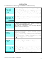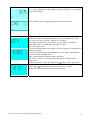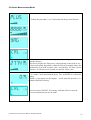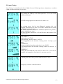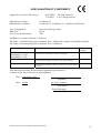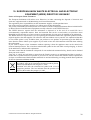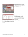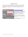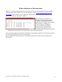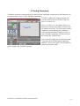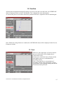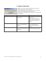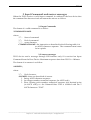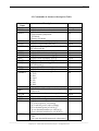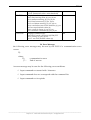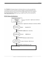
1
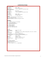
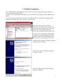
Release5 – August 05
Instruction Manual
Plus+
Laserpoint srl - Via Burona, 51 - 20090 Vimodrone (Milano) - Italy
Phone +39 02 27 400 236 - Telefax +39 02 25 029 161-www.laserpoint.it
LaserPoint srl-PLUS Instruction Manual- All Rights Reserved
1
TABLE OF CONTENTS
TABLE OF CONTENTS
2
1-GENERAL
4
1.1-Introduction
4
1.2-Unpackaging and Inspection
4
1.3-Power requirements
4
2-SPECIFICATIONS
5
3- PANEL DESCRIPTION
6
3.1-Front Panel
6
3.2-Top Panel
7
3.3-Bottom Panel
7
3.4-Rear Panel
7
4-BEFORE GETTING STARTED
8
4.1-Installation
8
4.2-How to Use the Keys
8
4.3-Wavelenght and UCF (User Calibration Factor) Selection
9
4.4-Power, Energy, FIT Operational Modes
9
4.5-Temperature Compensation
9
4.6-Analog Output
9
5-OPERATION
10
5.1- Initial Selections : Wavelenght and UCF (User Calibration Factor)
10
5.2-Power Measurement Mode
12
5.3-Laser Tuning
13
5.4-Energy Measurement Mode
14
LaserPoint srl-PLUS Instruction Manual- All Rights Reserved
2
5.5-Fit Measurement Mode
15
6-WARNING MESSAGES
16
7-MAINTENANCE AND SERVICE
17
7.1-Battery Change
17
7.2-On line servicing
17
7.3-Returns for Calibrations and Repair
17
8-WARRANTY
18
8.1-Limited Liability
18
9-DECLARATION OF CONFORMITY
19
LaserPoint srl-PLUS Instruction Manual- All Rights Reserved
3
1-GENERAL
1.1-Introduction
To exploit all possibilities offered by PLUS, we recommend to carefully read this manual.
Plus is the most versatile measurement monitor for thermal heads available on the market today. Its price-toperformance ratio is absolutely outstanding , since it has been specifically imagined and designed to be
everybody’s tool for laser measurement.
It allows wavelength correction for more precise measurements on the most popular lasers , bears a fast
analog bargraph for laser tweaking and has a wide dynamic range, measuring powers from 1mW up to 10KW
and energies from 1mJ to 300J.
Plus can be plugged to any of LaserPoint detectors, via a simple connection to the measurement head by
means of its standard Intelligent Interfacing System (IIS) and can operate on 3 different modes. Other than
power, it can measure energy and work as a FIT , or probe mode: this is the case of those applications that
do not need long term measurements and simply require once in a while laser power checks.
Plus can thus be used on the field , for service purposes, or in laboratory where he can make sophisticated
signal analysis with its optional SW.
External interfacing can be done with the Analog output or the digital RS232 .
1.2-Unpackaging and Inspection
Each instrument has been carefully inspected and tested prior to shipment . Unpack and assure that no
damage occurred during transport and handling.
Any damage must be immediately reported to Laser Point and to the Carrier.
Do not use the PLUS and its associated detector/s if the delivered parts look damaged, or if you suspect that
they do not operate properly.
1.3-Power requirements
Plus works both as a battery operated unit, using two 2 LR6 (AA -1.5 V) non -rechargable batteries, or
through the line , at 12 VDC –50mA, with its optional external power supply.
The battery holder is located on the bottom rear of the instrument.
LaserPoint srl-PLUS Instruction Manual- All Rights Reserved
4
2-SPECIFICATIONS
Power Meter Mode
Power Ranges:
1mW to 10kW
Resolution:
0.5‰ for any Full Scale
Response Time
<1-5 sec. ( depends on each specific head)
Energy Meter Mode
Power Range:
1mJ to 300J
Resolution:
0.5‰ for any Full Scale
Response Time:
<1-5 sec ( depends on each specific head)
FIT Mode
Power Ranges:
1mW to 10kW
Resolution:
0.5‰ for any Full Scale
Response Time:
4 sec (final value)
Tuning
-Displays a Digital Bargraph for Tuning Direction
-Displays Actual Power Value
-Displays Variations (as %) form Tuning Initial Value
Selections
Wavelenghts
EXC : UV and excimer laser (250-350nm)
VIS: Visible (400-700nm)
LD: Laser Diodes (800-900nm)
Yag: Nd-Yag (1064 nm)
Erb: Erbium (2943 nm)
CO2 : CO2 (10600nm)
User’s Own Calibration Factor
UCF
General
Digital Display:
4-digit LCD readout
Monitor accuracy:
±0.5%
Scales:
3 scales (00.00 / 000.0 / 0000) ,head dependent with 0.5‰ resolution
Analog Output:
0-2V ±1.0%
Digital Output:
RS-232 on DB9Connector
Temperature Compensation and Over-Temperature Alarm
Overload Alarm :
red Led warns for intermittent power use
Input voltage:
12VDC Adapter
Batteries:
2 LR6 (AA -1.5 V)
Battery life:
250 hours ; OFF State one year
Dimensions (mm) :
150 (W) x 105 (H) x 45 (D)
Weight:
500g
Operating environment:
°Storage Temperature:-10 to 60 ºC
° Range of Use :5 to 45 ºC
°Reference Conditions : 21 ± 4 ºC ;RH 20-80%
LaserPoint srl-PLUS Instruction Manual- All Rights Reserved
5
3- PANEL DESCRIPTION
3.1-Front Panel
Fig.1- Front Panel
1. -Green Led : measures mW, when lit
2. - Green Led : measures mJ, when lit
3. - 4 Digit LCD screen displays:
-7segments, 4 digit power/energy values
-measurement unit
-wavelength /UCF
- percent variation of power on small 3digit display
- offset (± VALUE)
-low battery
- Temperature/ Tuning bar
4. - Warning Green/Red Led
5. - Tuning and Power selection key . Also scrolls wavelengths and UCF
6. – Energy selection key. Also scrolls wavelengths and UCF
7. –ON/OFF Key- Also allows instrument zeroing and parameter confirmation
LaserPoint srl-PLUS Instruction Manual- All Rights Reserved
6
3.2-Top Panel
Fig.2- Top Panel
1- DB9 Connector –Female for RS232 connection
2- DB15 Connector –Female for detector connection
3.3-Bottom Panel
Fig.3-Bottom Panel
1- 3.5mm Mono Jack Plug for 0-2V Analog Output
2- 2.5mm Power Plug for 12V DC, 50 mA external power supply
3.4-Rear Panel
Fig.4-Rear Panel
1- Lift
2- Battery Holder: houses Q.ty 2 AA 1.5V batteries
LaserPoint srl-PLUS Instruction Manual- All Rights Reserved
7
4-BEFORE GETTING STARTED
WARNING! The user of this instrument must
be trained to the use of lasers and their
associated risks. LaserPoint is in no way liable
for any damage resulting from misuse,
careless or use above rated limits for the
instrument.
IMPORTANT: Take all the required safety
procedures to work with laser beams and
wear suitable protection glasses all the time!
Be extremely careful with radiation either
backreflected or backscattered from detector
surfaces, housings, mounts and stainless steel
post!
Measurement heads temperatures may reach
85°C.
4.1-Installation
Connect the PLUS to its associated detector head by means of the DB 15 connector located on
monitor top panel (fig2- Pos2). You may now press the ON/OFF key to start .
Allow at least 5 minutes of warm up, after turn-on, to achieve maximum stability of
electronics and for the thermal stabilization of detectors.
4.2-How to Use the Keys
The PLUS has been designed to provide easy and immediate access to all its functions. Three soft
touch keys , whose major functions are described below, govern the instrument :
1-ON/OFF (Zero). Press and release to switch the instrument ON; press for 3 sec to switch the
instrument OFF. During the measurement session pushing shortly on the key will Zero the stored
measurement value and display.
2-T/P. Pressing the T/P key for 2 sec gives access to the Tuning Function or allows return to the
Power Measurement Function.
The mW led, associated to the Power Measurement Function, lights for those low power
measurement heads whose full scale is set in mW: this is automatically done by the PLUS as it reads
the detector specifications stored within its DB15 connector.
3-E. Pressing the E key provides access to the Energy Measurement Function .
The mJ led, associated to the Energy Measurement Function, lights for those low power
measurement heads whose full scale set in mJ: this is automatically done by the PLUS as it reads the
detector specifications stored within its DB15 connector.
LaserPoint srl-PLUS Instruction Manual- All Rights Reserved
8
4.3-Wavelenght and UCF (User Calibration Factor) Selection
By selecting the band or wavelenght of your interest, the PLUS will read the corresponding
wavelength correction values based on spectral data measured from each coating or absorber which
are stored within the detector’s EEPROM . The PLUS display will show :
EXC : to mean the UV and excimer laser range (250-350nm)
VIS: to mean the visible range (400-700nm)
LD: to mean the Laser Diodes range (800-900nm)
Yag: to mean the Nd-Yag wavelength at 1064 nm
Erb: to mean the Erbium wavelength at 2943 nm
CO2 : to mean the CO2 wavelength at 10600nm
UCF: for the user’s own calibration factor
The wavelength/UCF selection is simply made by clicking the T/P and E keys to scroll up and down
the bands.
Allowable wavelengths are restricted to the head specific absorber type or coating: for this reason
some selections are inhibited on the PLUS.
4.4-Power, Energy, FIT Operational Modes
The PLUS can work on different operational modes. It can be used as a power meter, as an energy
meter or as a power probe , when working with the FIT heads.
The selection is automatically made by the monitor when it reads the detector EEPROM, as the unit
is switched on.
A FIT head can only provide values of laser power in measurements that last 4 seconds. This timing
is generated by an internal firmware and is sufficient to provide precise , yet once in a while,
readings. There is no need , for the user, to measure manually or provide the time window to the
laser shutter.
The Power Measurement Mode is set as a default function when the PLUS is switched on;
entering into the Energy Measurement Mode is simply accomplished by pushing the E key.
4.5-Temperature Compensation
Air cooled and FIT heads are provided with a temperature sensor used by the PLUS to linearize the
head response and advise, with a COOL message on the display, when the head has overtaken its
max allowable temperature.
For those heads not bearing the temperature sensor, the bar will be only displayed during the auto
initialization at instrument start up .
4.6-Analog Output
The Analog Output ranges from 0-2 Volts of head full scale , whose value is displayed when the
head is switched on.
Power/Energy values corresponding to the output voltage are given by the following formula:
VAnOut
W=
Wfs
2
EXAMPLE:
With a display reading of 1780W and 3000W full scale, VAnOut =1,186 V
The Analog Out can bear an override of 125%, up to 2.5V.
LaserPoint srl-PLUS Instruction Manual- All Rights Reserved
9
5-OPERATION
5.1- Initial Selections : Wavelenght and UCF (User Calibration Factor)
1 – Connect the PLUS monitor to the Detector Head via its DB15 male
connector. (Fig 2- pos.2)
Switch the instrument ON (Fig1- pos.6): the PLUS logo appears on the
screen. The temperature bar also lights-on, scaling up.
This preliminary phase last 4 sec: the instrument acquires all
parameters from the measurement head and learns the kind of SW
necessary to elaborate signals .
2-The PLUS starts a circuit a self-diagnostic procedure, during which
all screen segments and bars are shown .
3- The above cycle completed, the display will show the nominal, full
scale power in W or mW of the detector in use
Note: if the head is programmed to provide both energy and power,
the display will however show power .
4 –The next message to appear is the stored wavelength (e.g. YAG),
hold from a former session.
If there is no need for a change, confirm by pressing the ON-OFF key
(Fig1-pos 6) .
If the detector will operate at a different wavelength, scroll up or down
the λ buttons (Fig1. pos 5 & 7) to select another .
5 –Once the wavelength for a new measurement has been selected, e.g.
CO2, confirm by pressing the ON-OFF button (Fig1-pos 6)
6–When confirming the new wavelength, a zeroing is also
accomplished. The display will show the selected new wavelength
while the (Fig1-pos 4) led will blink green for 2 sec, to confirm the
zeroing.
Note: no radiation must hit the detector during this operation.
LaserPoint srl-PLUS Instruction Manual- All Rights Reserved
10
7-A ± sign appearing on the display will mean that there is a residual
offset after zeroing.
Press ON/OFF for zeroing again until the offset is removed.
8-The User Calibration Factor gives the customer the possibility to
modify the value of calibration sensitivity, in a reversible way, from
01.% up to 999.9% (or from 1/1000 up to 10 times).
The original sensitivity is set as 100% so, any time it is needed to
recupe that value, it is sufficient to go back to 100.0
The UCF can be used :
-in case of light damages on coatings ( for major burns it is suggested to
change the sensor)
-in case of detection after partializing devices (eg filters, beamsplitters,
mirrors) to track the main beam
-have measurements aligned to other references
The UCF is effective on each measurement mode of Plus (power ,
energy, Fit) .
To access the UCF scroll up or down the λ buttons (Fig1. pos 5 & 7)
Once it has been selected, the existing UCF can be changed by acting
on the same λ pushbuttons to increase/ decrease its value .
Press ON/OFF to confirm and start measurements
LaserPoint srl-PLUS Instruction Manual- All Rights Reserved
11
5.2-Power Measurement Mode
1- Follow the procedures 1 to 7 as described in the previous Section.
2- Measurements are automatically done by sending the laser beam
onto the detector.
The time to display the final power value depends on the head in use .
A fast accelerating alogorithm within the Plus will strongly reduce the
intrinsically slow head response time; nevertheless, for some slower
detectors it will take a few seconds to reach the 100% value
3- To make a new measurement press Zero (ON/OFF) to refresh the
display.
Should a ± sign appear on the display, it will mean the presence of a
residual offset after zeroing.
Press once more ON/OFF for zeroing, until the offset is removed.
A new measurement can now be done.
LaserPoint srl-PLUS Instruction Manual- All Rights Reserved
12
5.3-Laser Tuning
Laser Tuning is only allowed in Power Mode. Proceed, following the next instructions, to achieve
a high resolution tweaking of your laser.
1-By pushing the T/P key on the front panel for > 2 sec, the TUNE
function is activated.
A TUNE message appears on the screen for about 1 sec.
The existing power level is then displayed, together with the
bargraph, positioned at its center; it will move downward or upward
depending on tuning direction.
The smaller digits show the power variations, expressed as percent ,
from the initial power value .
The max allowable variation is ±12% of full scale, after which a Zero
has to be done.
2-EXAMPLE A:
-Initial value was 2774W.
-After tweaking the new value is 2635W.
-The bargraph shows the direction of tuning and a 5% drop (-) of
power .
EXAMPLE B:
-A better tuning has been done and value is now 2996W
- The bargraph shows the direction of tuning and an 8% increase of
power
EXAMPLE C:
-Tuning has increased the power level to above 12% (19% on the
example): the bargraph is at its limit. It is necessary to reset.
3- Shortly push the T/P key to Zero both bar and % value.
Tuning may continue as described above.
LaserPoint srl-PLUS Instruction Manual- All Rights Reserved
13
4- To sort the Tuning Function and return to Power Measurement
Mode, simply press the T/P key for >2 sec.
The bar, will again show the head temperature (if this function is
activated).
5.4-Energy Measurement Mode
The PLUS monitor allows the measurement of single shot energies , function available on most
of thermal heads manufactured by LaserPoint .
1 – Follow the procedures 1 to 7 as described in section 5.1
The Energy Mode will be enabled by pushing the E button
(Fig1.-Pos 7)
2 – Press the Zero button (Fig.1 Pos 6) and arm the meter . A
“READY” (rdy) message appears and the led (Fig1-Pos 4) lights
as steady green .
3 –When an incoming signal overtakes a preset threshold, a
“TRIGGERED” (tr’d) message is displayed and the led (Fig1Pos 4) lights as flashing green. Thresholds are specific for each
head model and typically are set at 2% of the head full scale.
4 – The measured value appears preceded by J (Joule), the energy
measurement unit .
The led (Fig1-Pos 4) shifts from green to steady red, to show that
the head is reaching its thermal equilibrium; during this period
any further measurement is inhibited.
The inhibition period is specific for each head and is safely set
to be 3-4 times the head intrinsic response time : it can last up
to several seconds .
– As soon as the led (Fig1-Pos 4) turns to green, the unit is ready
to accept another laser pulse.
Press the E key again to return to power.
LaserPoint srl-PLUS Instruction Manual- All Rights Reserved
14
5.5-Fit Measurement Mode
1-Follow the procedures 1 to 5 of Section 5.1
The Plus will automatically recognize that its working mode is
Fit
2- After the wavelength has been confirmed,
appears on the screen.
the FIT logo
3-To carry on the first or any successive measurement, press and
release the Zero key to make an automatic zeroing. The LCD
displays “CAL” and the Led turns to steady green .
The PLUS is now armed and both the FIT logo and green led
will blink.
4– Center the probe to the laser path and start measurements by
opening the laser shutter. Take care that only the sensor surface
intercepts the laser beam.
5– Measurement will start automatically, shown by a 4 sec.
count down and displayed on the LCD by “Run ”; the LED
blinks green . At the same time, the bar graph scales up showing
the temperature increase in the sensor head, if appreciable.
LaserPoint srl-PLUS Instruction Manual- All Rights Reserved
15
6 - The measurement is over when the Led turns into steady red.
Remove the probe from the laser beam: the display shows the
measured power, and the remaining thermal capacity. If the bar
graph is below full scale, more measurements can be carried out
before cooling the sensor head.
The next measurement can be executed after the Led
automatically shuts off (approx. 5 to 25 sec, depending on the
head). To perform a new measurement go back to pos 6.
6-WARNING MESSAGES
2 –Should the measurement head reach its limit temperature,
the LCD will show a COOL message , while the corresponding
Led (Fig1-pos 4) turns into an intermittent red.
Immediately switch off the laser or close the laser shutter!
NOTE:
-If you are using a FIT head, use forced air or let the head cool
down spontaneously. Never use water or other liquids!
-If you are using a head for power or energy measurement , this
will mean a problem in the refrigerating circuit ( e.g.low water
pressure, lack of fluid , obstructions) or at the heat exchange
system for air cooled heads (e.g. fan, ambient Temp. , etc.)
Immediately spot and remove the causes.
3 – Should the head be exposed to levels exceeding its
allowable full scale, the LCD will then show four short bars,
indicating an overflow, rather than the standard numerical
value.
4 - When the head is not properly connected, the LCD displays
a “HEAD” warning message ; in this case check whether the
connector is properly matched.
The PLUS automatically switches off after 10 sec.
1 . Battery life is 250hours in condition of normal use . A
“LOW BATTERY”. warning signal appears on the LCD display
as a flashing battery :30-50 hours of residual use are available
before the battery defintely dies.
LaserPoint srl-PLUS Instruction Manual- All Rights Reserved
16
7-MAINTENANCE AND SERVICE
7.1-Battery Change
When changing the batteries, respect the polarity: inverting batteries will definitely damage the
instrument.
7.2-On line servicing
For any urgent question on the instrument you may apply
[email protected]
at [email protected] or
7.3-Returns for Calibrations and Repair
Prior to shipment:
1-Ask directly to LaserPoint or one of his Distributors for the RMA (Return Material Authorization)
Number. This will be issued and quotation will follow immediately after the receipt of material in
LaserPoint .
2-Report: -Model Number -Serial Number -Purchase Order Number and date
-Shortly describe encounterd problems (if any)
3-Deliver to (shipping and insurance prepaid): LASERPOINT s.r.l. -Via Burona, 51 –Vimodrone
(Milano) –I20090 Italy or to one of its Distributors.
Return time: Time to calibrate instruments normally occurs within 10 working days after receipt .
A faster service is available at an additional charge (please ask)
LaserPoint srl-PLUS Instruction Manual- All Rights Reserved
17
8-WARRANTY
The PLUS Laser Power/Energy Monitor is delivered with a one-year (1) warranty from date of
shipment.
Warranty applies against material and/or workmanship defects, when the PLUS has been properly
installed, maintained and is used under normal operating conditions; the warranty does not cover
damages related to accident or misuse. The warranty does not cover any damage due to battery
leakage or misuse.
During the warranty period LaserPoint srl will repair or, at his option, replace any PLUS monitor
that proves to be defective provided the parts are returned to LaserPoint customer service facility or
another facility authorized by LaserPoint.
Any attempt by an unauthorized person to alter or repair the product voids the warranty.
No other expressed warranty is given by LaserPoint.
In case of system malfunctioning or failure, contact LaserPoint directly or its local distributor to
obtain a Return Authorization Number (RMA). This number must be reported on the outside of the
shipping container.
The material should be returned to, transportation and insurance prepaid:
LaserPoint srl
Via Burona,51
I-20100Vimodrone (Milano)
Italy
E-mail: [email protected]
LaserPoint assumes no risk for damages occurred in transit.
8.1-Limited Liability
Prior to returning any unit, please provide a description of failure or encountered problems and
consult the Service Dept. at LaserPoint to avoid unnecessary shipments.
LaserPoint will, at his option, repair or replace all defective parts without charge; however if
LaserPoint determines that failure was caused by misuse, alterations, accident or abnormal condition
of operation or handling, Customer will be billed for the repair and the repaired product will be
afterwords returned , transportation and insurance prepaid.
LaserPoint srl-PLUS Instruction Manual- All Rights Reserved
18
9-DECLARATION OF CONFORMITY
Application of Council Directive(s) :
89/336/EEC The EMC Directive
73/23/EEC Low Voltage Directive
Manufacturer’s Name :
Manufacturer’s Address :
LaserPoint srl.
LaserPoint srl- Via Burona, 51- Vimodrone-20090 Italy
Type of Equipment:
Model No.:
Year of test & manufacture:
Laser Power/Energy Meter
PLUS
2003
Standard(s) to which Conformity is Declared:
EN 50081-1:1992 Emission generic standard - Part 1: Residential, commercial and light industrial
EN 50082-2:1995 Immunity generic standard - Part 1: Industrial
Standard
Description
Performance
Criteria
Class B
EN 55022:1994
amendment 1: 1995
amendment 2: 1997
EN 61000-4-2:1995
Limits and methods of measurement of radio interference
characteristics of information technology equipment
Electromagnetic compatibility (EMC) – Part 4: Testing and
measurements techniques- Section 4.2: Electrostatic discharge.
Class B
EN 61000-4-4:1995
Electromagnetic compatibility (EMC) – Part 4: Testing and
measurements techniques- Section 4: Electrical fast transient/burst
immunity.
Class B
I the undersigned, hereby declare that the equipment specified above
conforms to the above Directive(s) and Standard(s).
Place: Vimodrone -Italy
(Signature)
Date : 4.12.03
Dr Luigi Argenti
(Full Name)
Project Manager
(Position)
LaserPoint srl-PLUS Instruction Manual- All Rights Reserved
19
10. EUROPEAN UNION WASTE ELECTRICAL AND ELECTRONIC
EQUIPMENT (WEEE) DIRECTIVE 2002/96/EC
Notice to European Union Customers:
The European Parliament will enforce new Directives in 2006 concerning the disposal of electrical and
electronic equipment such as the Monitoring and Control Instruments.
The regulations place responsibilities on the instruments supplier and the purchaser/user.
One of the actions required by suppliers is to inform users of their obligations.
The present instrument has been assessed in accordance with the European Parliament Directive2002/96/EC
on Waste Electrical and Electronic Equipment, usually referred to as the WEEE Directive.
The WEEE Directive requires that the instrument is disposed of at the end of its useful life ina n
environmentally responsible manner. Parts and materials that can be re-used and/or re-cycled have been
identified in order that the use of new resources and the amount of waste going for landfill can be minimised.
The WEEE Directive requires that if you are replacing the instrument with a new equivalent product from the
original supplier, then that supplier can collect the old item without cost to yourself. It is emphasised that this
no-cost return option is only available when you purchase a new product of equivalent type that fulfils the
same function. Please inform your supplier of your wish to have the old instrument collected when ordering
the replacement.
If you wish to dispose of the instrument without replacing it then the appliance must not be mixed with
unsorted municipal waste. The crossed-out wheeled bin symbol on the unit label or unit packaging, as shown
in the table below, indicates this requirement.
You must ensure that the instrument is disposed of at an authorised treatment facility; details can be obtained
from your local council.
Your rôle is critical and will help to ensure that the Earth’s resources are maintained and that as much reusable and re-cyclable material as possible is processed. It will also ensure that landfill volume requirements
are kept at a minimum and that hazardous materials are not buried thereby providing potential future problems
for the environment and human health.
Wheeled bin symbol and description
The symbol apply to all LaserPoint electronic products placed
on the European Market after August 13, 2005.
LaserPoint will affix the wheeled bin symbol with a bar to
appropriate products. The bar indicates that the product was
placed on the market after August 13, 2005.
The WEEE Directive comes into force in January 2006.
LaserPoint srl-PLUS Instruction Manual- All Rights Reserved
20
PLUSSoftUsb
Power Meter Mode
User Manual (Vers. 1.03)
Laserpoint srl - Via Burona, 51 - 20090 Vimodrone (Milano) - Italy
Phone +39 02 27 400 236 - Telefax +39 02 25 029 161
www.laserpoint.it
LaserPoint srl PLUSSoftUsb User Manual All Rights Reserved
1
Contents
CONTENTS
2
1. PLUSSOFT INSTALLATION
3
2. SWITCH-ON PROCEDURE
4
2.1 System Requirements
4
4
4
4
2.1.1 Software Requirements
2.1.2 RAM and Hard Disk Space Requirements
2.1.3 Hardware Requirements
2.2 Starting sequence
4
3. STARTING WINDOW
4
4. POWER METER WINDOW
5
4.1 Handling of Measurements
5
4.2 Handling of Process Parameters
6
4.3 Handling of Statistical Functions
6
4.4 Handling of Screen Plots
6
5. MEASUREMENT PROCEDURES
7
6. SAVE MEASUREMENT ON FILE PROCEDURE
8
6.1 Continuous Saving
8
6.2 Saving of Single Measure
10
7.STATISTICS PROCEDURE
12
8.SAVE STATISTICS ON FILE PROCEDURE
13
9. TUNING PROCEDURE
14
10. OVERFLOW
15
11. COOL
15
12. ERROR CONDITIONS
16
13. SAFETY
17
LaserPoint srl PLUSSoftUsb User Manual All Rights Reserved
2
1. PLUSSoft Installation
Your PLUSSoft PM Mode handles the PLUS monitor acquisition electronics when working in
Power Meter Measurement Mode.
Contact LaserPoint for further information on the PLUSSoft for the Energy and FIT Measurement
Modes.
If a previous version of the PLUS software is installed in your PC, uninstall it using Application
Installation (from the Start menu, Settings, Control panel).
Insert the CD in your PC (the PLUS
electronics is disconnected); open the CD
folder with My Computer and left click the
mouse to start the Application Setup .
Follow the installation program instructions.
Switch on the PLUS Monitor following the
procedures described within its Instruction
Manual. Connect the PLUS Monitor to the
host PC device by the supplied Usb cable.
Follow the New Hardware Wizard in order to
install the PLUS’s Drivers.
Choose not connect to Windows Update to
search for software
Choose the Recommended automatically
software installation.
LaserPoint srl PLUSSoftUsb User Manual All Rights Reserved
3
2. Switch-On Procedure
2.1 System Requirements
2.1.1 Software Requirements
Windows® 2000, Windows 98.
2.1.2 RAM and Hard Disk Space Requirements
64 MB of RAM (recommended), 32 MB of RAM (minimum)
600 kB of free disk space for installation folder.
2.1.3 Hardware Requirements
Intel Pentium® 133 or better, or compatible processor (hardware must be supported by Microsoft
for the operating system used)
800 x 600 VGA video display with 256 colors (1024 x 768 or higher recommended)
CD-ROM drive for initial installation only
Windows-supported display adapter
Mouse or other pointing device
Usb 2.0 port
2.2 Starting sequence
1) Switch on the PLUS Monitor following the procedures described within its Instruction
Manual.
2) Connect the PLUS Monitor to the host PC device by the supplied Usb cable.
3) From the same folder used to install the PLUSSoftUsb, run the Application
PLUSSoftUsb.exe.
3. STARTING WINDOW
Quit: to exit the program
Start: run the Power Meter window.
LaserPoint srl PLUSSoftUsb User Manual All Rights Reserved
4
4. POWER METER WINDOW
4.1 Handling of Measurements
HeadModel: shows the detector head model in use
Lambda: shows the detector’s calibration wavelength
SN: shows the head serial number
Actual Time: shows present date and time
POWER (W/mW): shows the measured power value
User Cal Factor: this number will multiply to the actual measured value to calculate the corrected
value. For example, if you are measuring the laser beam passing through the 99.9% back reflector
of a laser (giving 1/1000th of the real value), enter 1000 in the dialog box. The PLUSSoft will
display the laser’s power rather than the measured 0.1%.
TEMPERATURE (°C): shows the temperature on those heads provided with temp. sensor
ZERO: accomplishes an automatic Zeroing (refer to the PLUS User Manual)
SAVE: Enables the automatic function to save on file done measurements; this function is active
when the Led is green.
PRINT: print on connected printer the Power Meter Window
TUNING: Enables the Tuning Function
QUIT: leaves the program
LaserPoint srl PLUSSoftUsb User Manual All Rights Reserved
5
4.2 Handling of Process Parameters
It is possible to set two threshold power level in order to monitor if the power remains within fixed
limits. This feature extends the PLUS applicability to rigorous power control and monitoring,
necessary in most application.
Process Parameters: when power measured is within the thresholds limits the rectangular Led is
green; when outside is red. The overtaken threshold is indicated by a red round Led.
MAX/Min Power Level: sets process thresholds. Insert the desired threshold value (Max. 13000) and
press Enter; if the Min Threshold< Max Threshold condition is satisfied, the value is displayed and
stored in the SetUp file.
4.3 Handling of Statistical Functions
Pmax(W): Shows the max power value measured during the last acquisition interval
Pmin(W): Shows the min power value measured during the last acquisition interval
Pavg(W): Shows the average value of power measured during the last acquisition interval
P max − P min
PTP(%): Shows the Peak-to-Peak stability based on the formula PTP =
⋅100
P max
STD(W): Shows the measurement Standard Deviation based on the formula
n
STD =
∑ ( Pi − Pavg )
2
i =1
n −1
STD
⋅100
Pavg
Duration(s): Shows the duration of the acquisition interval in sec.
Elapsed Time(s): Shows the time elapsed after acquisition started.
START: Starts acquisition
STOP: Ends acquisition
SAVE: enables an automatic saving on file of done statistical measurements; the function is enabled
when the Led is green.
RMS(%): Shows the RMS stability based on the formula RMS =
4.4 Handling of Screen Plots
The screen plot displays measured power (blue lines) and preset values of thresholds (red lines).
Graph Power Max/Min (W): sets the Power axis on the power plot. Insert the desired full scale and
press Enter: measured values will be automatically scaled.
Graph Time: sets the Time axis on the power plot; available time scales are 60(sec), 2(min), 5(min),
30(min), 1(hour), 12(hours). Press Enter to confirm. If a lower time scale is selected, data on plot
are refreshed.
LaserPoint srl PLUSSoftUsb User Manual All Rights Reserved
6
5. Measurement Procedures
1. If needed, set the MAX and Min process thresholds, by means of MAX/Min Power Level.
2. If a successive measurement has to be stored, refer to the section 6. Save on File
Procedures
3. Verify that all safety conditions are
satisfied; refer to section 13. Safety
4. If a detector’s offset is present , a Zero
can be made by left clicking with
mouse on the ZERO key. The display
POWER (W/mW) will zero, together
with the plot of power on the graph.
5. Verify that no laser beam or other
spurious radiation is striking on the
detector; align the measurement head
to the optical path and open the laser
shutter. Verify that only the sensor
surface is intercepting the laser beam .
6. The measured power value will be shown on the numerical display POWER(W/mW) and the
plot will report the power behaviour vs time.
7. The process Leds will light: green when power is within thresholds, red when power is not.
8. For starting statistical measurements or save data, refer to the section 7.Statistics
procedures
NOTE: In order to avoid thermal overloads to the measurement head LaserPoint suggest to not
exceed a limit temperature of 80-82°C.
LaserPoint srl PLUSSoftUsb User Manual All Rights Reserved
7
6. Save Measurement on File Procedure
Whenever measurement data need to be saved on files, the SAVE function must be enabled first,
following the described procedure. The Led accompanying the SAVE key, when green, shows that
this function is active.
Data may be saved continuously or the actual value may be saved at any time under user selection,
as a single measurement.
6.1 Continuous Saving
1. Left click on SAVE with the mouse.
2. On the Save window select the Saving
Mode Continuous
3. Select the Sampling Time for the
saving function (1, 15, 60sec; 5, 30min;
1h)
4. Left click on START
5. Select the folder on the Save As
window and insert the file name. The
Led will turn green. At the end of each
Sampling Time the power value will
be automatically saved
6. To disable the SAVE function click on
the key; the Led turns red.
Note: verify that the selected file is not already
open on your PC during measurement.
LaserPoint srl PLUSSoftUsb User Manual All Rights Reserved
8
In case new measurements have to be saved on
an existing file, without deleting stored data,
confirm the substitution of file by left clicking
with the mouse on the Yes key.
The structure of saved file ( .txt format), shown
in the picture is:
- headline, reporting head model, calibration
wavelength, serial number, date and starting
time of save
- seven columns reporting the time elapsed at
time intervals of Sampling Time, measured
power values, process conditions, process
thresholds, Head temperature, and user
calibration factor.
Note: It is also possible to import the saved file in a spreadsheet (e.g. Excel); use Excel to open the
text file importing data and use tab as data limiter.
Do not modify the .txt file to preserve, for future measurements, both its structure and correct
functioning .
LaserPoint srl PLUSSoftUsb User Manual All Rights Reserved
9
6.2 Saving of Single Measure
1. Left click on SAVE with the mouse.
2. On the Save window select the Saving
Mode Single Measure
3. Left click on START
4. On the Save As window select the
folder and insert the file name. The Led
will turn green, and Trg Save button
will be displayed.
5. Every time the user left clicks on
TrgSave key, the actual power will be
saved
6. To disable the SAVE function, click on
the key; the Led turns red and Trg Save
button will be hidden.
Note: verify that the selected file is not already
open on your PC during measurement.
LaserPoint srl PLUSSoftUsb User Manual All Rights Reserved
10
In case new measurements have to be saved,
without deleting stored data, on an existing file
confirm the substitution of file by left clicking
with mouse on the key Yes.
The structure of saved file ( .txt format), shown
in the picture is:
- headline, reporting head model, calibration
wavelength, serial number, date and the
starting time of save
- seven columns reporting the time of saving,
measured power values, process conditions,
process thresholds, Head temperature, and user
calibration factor.
Note: It is also possible to import the saved file in a spreadsheet (e.g. Excel); use Excel to open the
text file importing data and use tab as data limiter.
Do not modify the .txt file to preserve, for future measurements, both its structure and correct
functioning .
LaserPoint srl PLUSSoftUsb User Manual All Rights Reserved
11
7.Statistics Procedure
Set the acquisition time interval during which the statistics of measurements must be calculated;
digit the time value (greater than 1) in Duration(s). For acquisition intervals lower than 1.000 sec
sampling time is 1 sec; for intervals lower than 10.000 sec sampling time is 10sec; for intervals
lower than 100.000 sec sampling is 100 sec. It is not possible to set acquisition periods above
100.000 sec.
To record statistical values refer to section
8.Save statistics on file procedure
Left click the mouse on Start to begin
statistical calculations. Select within the dialog
window whether statistical calculations have
to run continuously or just for a single
acquisition interval. All indicators within the
STATISTICS section will be zeroed.
At the end of each acquisition interval, the
calculated statistical values will be displayed
on the screen and saved on file, if this function
is enabled.
To end statistical measurements left click the
mouse on the STOP key .
LaserPoint srl PLUSSoftUsb User Manual All Rights Reserved
12
8.Save statistics on file procedure
Whenever statistical information have to be saved on file, the saving function must be enabled
following a procedure similar to the one described on section 6. Save Measurement on File
Procedure; the SAVE key is now within the STATISTICS section. The associated Led, when
green , shows that the function is enabled.
The structure of saved file ( .txt
format), as shown in the picture, is:
- headline, reporting head model,
calibration wavelength, serial number,
date and time of starting save
- eleven columns reporting the
calculated values of statistical
measurements, updated at each
acquisition time interval measurement,
sampling time and number of samples within each acquisition interval.
Note: It is also possible to import the saved file in a spreadsheet (e.g.Excel): use Excel to open the
text file importing data and use tab as data limiter.
Do not modify the .txt file to preserve, for future measurements, both its structure and correct
functioning
LaserPoint srl PLUSSoftUsb User Manual All Rights Reserved
13
9. Tuning Procedure
Visualizes variations of measured power and stores the maximum reached power; this function can
be used for laser source or laser machines adjustment.
TUNING: enables the Tuning function and
sets the actual power as reference value for
Power Variation (%).
Power Variation (%): the display shows as a
numerical value the percentage variation from
the initial power level. Two bars show positive
variations (green) and negative variations
(red); bars are limited to a range of ±25%: in
case of broader variations, zero the reference
by pressing the TUNING key.
Power Max(W): shows the reached maximum
value after the TUNING function has been
enabled. To zero press QUIT and TUNING to
enable the function again.
QUIT: disables the TUNING function.
LaserPoint srl PLUSSoftUsb User Manual All Rights Reserved
14
10. Overflow
All times the measurement head will undergo to power levels above its full scale, an OVERFLOW
alarm is displayed. Refer to the PLUS Monitor User’s Manual for more information.
As soon as the power level returns below the permitted full scale, acquisition will be enabled again.
Note: When the saving function is enabled, the OVERFLOW alarm will be displayed in the Process
Parameter column.
11. Cool
Whenever the temperature of detector head is
above its limit, this will be displayed as a
COOL alarm (red).
In this cases, switch the laser off and cool the
head taking care not to contaminate the
absorbing surface.
Note: occasional dirt or contamination of
absorbing surfaces may compromise system
performance both regarding damage thresholds
and measurement precision.
LaserPoint srl PLUSSoftUsb User Manual All Rights Reserved
15
12. ERROR CONDITIONS
Whenever an error condition in the Software is detected , a
window claiming the error is displayed.
The meaning of error windows and how to solve the related
problems are displayed in the following table.
In any case, by left clicking the mouse on OK the program will
be terminated.
Error Window
COMMUNICATION ERROR
Conditions
No communication between
PLUS and PC.
COMMUNICATION ERROR
Communication between PLUS Check the connection cable
and PC is interrupted during
between PLUS and PC;
operation.
Check the PLUS electrical
supply .
Communication between
Check connection between
measurement head and PLUS is measurement head and PLUS.
interrupted.
DETECTOR HEAD ERROR
LaserPoint srl PLUSSoftUsb User Manual All Rights Reserved
Solutions
Check the cable connecting
PLUS to PC;
Check connection between
PLUS and measurement head;
Check the PLUS electrical
supply.
16
13. Safety
WARNING!
The user of Power/Energy measurement instruments must be trained to the use of lasers and their
associated risks (ref. EN 60825). LaserPoint is in no way liable for any damage resulting from
misuse, careless or use above rated limits for the instrument.
IMPORTANT: Take all the required safety procedures to work with laser beams and wear suitable
protection glasses all the time!
Be extremely careful with radiation either back-reflected or back-scattered from detector surfaces,
housings, mounts and stainless steel post!
Measurement heads temperatures may reach 85°C.
LaserPoint srl PLUSSoftUsb User Manual All Rights Reserved
17
PLUS
USB Communication Interface
(Rev. 08-Nov06)
Laserpoint srl – Via Burona, 51 – 20090 Vimodrone (Milano) – Italy
Phone +39 02 27 400 236 – Telefax +39 02 25 029 161
www.laserpoint.it
________________________________________________________________________________
Laserpoint srl – PLUS USB Communication Interface – All Rights Reserved
Pag. 2 / 13
Table of Contents
Table of Contents ..........................................................................................................................2
1 Installation...................................................................................................................................3
2 Input Commands and answer messages ................................................................................4
2.1 Input Commands ................................................................................................................4
2.2 Answer messages ................................................................................................................4
2.3 Commands & Answers description Table.......................................................................5
2.4 Error Message ......................................................................................................................6
3 Annex 1: FTD2XX.DLL Dynamic Library ..............................................................................7
________________________________________________________________________________
Laserpoint srl – PLUS USB Communication Interface – All Rights Reserved
Pag. 3 / 13
1 Installation
Connect the PLUS electronics through the USB 1.1 port to the host PC device by a
USB cable A to B type.
Include in your Code the FTD2XX.DLL Dynamic Library (described in Annex 1) for
Windows in order to write your application.
________________________________________________________________________________
Laserpoint srl – PLUS USB Communication Interface – All Rights Reserved
Pag. 4 / 13
2 Input Commands and answer messages
When the PLUS receives a valid input command, it confirms to the host device that
the command has been received and return the answer as follows.
2.1 Input Commands
The format of a valid command is as follow:
*COMMANDNAME:
where:
“*” : Start of command
“:” :
End of command
“_” : space character
COMMANDNAME : the instruction as described in the following table; it is
an ASCII character sequence. The command name must
be in capitals.
2.2 Answer messages
PLUS device send a message through USB interface only if it received an Input
Command from the Host Device. Maximum response time from PLUS is ~100msec.
The format of an answer is as follow:
ANSWER ;
where:
“;” :
End of answer
ANSWER : there are three kind of answer
1. String: ASCII character sequence
2. Int: integer number, numerical sequence (in ASCII code)
3. Float: floating point number, numerical sequence plus decimal point
(in ASCII code); ex. the NumericValue 23.45 is codified with the 5
ASCII characters “23.45”.
________________________________________________________________________________
Laserpoint srl – PLUS USB Communication Interface – All Rights Reserved
Pag. 5 / 13
2.3 Commands & Answers description Table
Command
Name
HEADN
SERNU
KEFUN
WSENS
OPDAC
PMSEW
STHFW
HOFTF
ENOMJ
JSENS
ODACJ
EMSEJ
STHEJ
HOFTE
LAMBDA
PNOMW
ZERO
OUTPM
TEMP
WTFIT
VISCA
LEDPRO
Description
Displays the Head model
Displays the Head serial number
Displays SW measurement’s type:
0: Power Meter (PM) mode
1: FIT Mode
2: Energy (E) Mode
Displays Head sensibility (mV/W)
Displays Output DAC (mV/W)
Displays maximum power value the Head
can withstand (W)
Displays START threshold (W) in FIT mode
Displays FIT inhibition time (sec)
Displays Head nominal energy (J)
Displays Head sensibility (mV/J)
Displays Output DAC (mV/J)
Displays maximum energy value the Head
can withstand (J)
Displays START threshold (J) in E mode
Displays E inhibition time (sec)
Displays selected wavelength:
01: CO2
02: Erb
04: YAG
08: LD
16: VIS
32: EXC
Displays Head nominal power (W)
Arms PLUS in FIT or E mode; zeroing PLUS
in PM mode
Displays measured power/energy (W/J)
Displays Head temperature x 10 (°C)
Displays FIT waiting time (sec)
Displays measured value’s format mode:
0, 1, 2: W for power, J for energy
3, 4, 5: mW for power, mJ for energy
0-3: no decimal point (ex. 10 W/J)
1-4: one decimal number (ex. 10.3 W/J)
2-5: two decimal number (ex. 10.35 W/J)
Displays process parameters state:
1: OFF
2: OK (min threshold<measured value<max)
Answer
String
Int
Int
Float
Float
Float
Float
Int
Float
Float
Float
Float
Float
Int
Int
Float
“ok”
Float
Int
Int
Int
Int
________________________________________________________________________________
Laserpoint srl – PLUS USB Communication Interface – All Rights Reserved
Pag. 6 / 13
STATUS
STATUSE
3: High (measured value > max threshold)
4: Low (measured value < min threshold)
Displays condition byte:
bit 0: arm/zeroing done; (1) yes, (0) no
bit 1: measure running; (1) yes, (0) no
bit 2: Head connected; (1) yes, (0) no
bit 3: cool alarm running; (1) yes, (0) no
bit 4: wait before start a new measure; (1) yes
bit 5:not used; default value (0)
bit 6: overflow alarm; (1) yes, (0) no
bit 7: termistor connected; (1) yes, (0) no
Displays condition byte:
bit 0: PLUS mode; (1) Energy,(0) PM/FIT
bit 1: Tuning; (1) yes, (0) no
bit 2-7: not used; default values (0)
Int
Int
2.4 Error Message
the following error message may be sent by the PLUS if a communication error
occurs:
??;
where:
?? :
“;” :
communication error
End of answer
An error message may be sent for the following error conditions:
Input command not started with * character
Input command does not correspond with the command list
Input command not in capitals
________________________________________________________________________________
Laserpoint srl – PLUS USB Communication Interface – All Rights Reserved
Pag. 7 / 13
3 Annex 1: FTD2XX.DLL Dynamic Library
TABLE OF CONTENTS
D2XX Driver Architecture ....................................................................8
DLL Functions .....................................................................................9
________________________________________________________________________________
Laserpoint srl – PLUS USB Communication Interface – All Rights Reserved
Pag. 8 / 13
The FTD2XX.DLL Dynamic Library for Windows allows you to write your application.
The architecture of the FTD2XX.DLL drivers consists of a Windows WDM driver that
communicates with the device via the Windows USB Stack and a DLL which interfaces
the Application Software (written in VC++, C++ Builder, Delphi, VB etc.) to the WDM
driver. The FTD2XX.DLL interface provides a simple, easy to use, set of functions to
access PLUS control card.
Variables
UCHAR unsigned char (1 byte).
PUCHAR pointer to unsigned char (4 bytes).
PCHAR pointer to char (1 byte).
DWORD unsigned long (4 bytes).
FT_HANDLE DWORD.
Errors
UFT_STATUS (DWORD)
FT_OK = 0
FT_INVALID_HANDLE = 1
FT_DEVICE_NOT_FOUND = 2
FT_DEVICE_NOT_OPENED = 3
FT_IO_ERROR = 4
FT_INSUFFICIENT_RESOURCES = 5
FT_INVALID_PARAMETER = 6
FT_INVALID_BAUD_RATE = 7
FT_DEVICE_NOT_OPENED_FOR_ERASE = 8
FT_DEVICE_NOT_OPENED_FOR_WRITE = 9
FT_FAILED_TO_WRITE_DEVICE = 10
FT_EEPROM_READ_FAILED = 11
FT_EEPROM_WRITE_FAILED = 12
FT_EEPROM_ERASE_FAILED = 13
FT_EEPROM_NOT_PRESENT = 14
FT_EEPROM_NOT_PROGRAMMED = 15
FT_INVALID_ARGS = 16
FT_OTHER_ERROR =PLUS
17
Control Card
________________________________________________________________________________
Laserpoint srl – PLUS USB Communication Interface – All Rights Reserved
Pag. 9 / 13
DLL Functions
FT_ListDevices
Description Gets information concerning the devices currently connected. This
function can return such information as the number of devices connected,
and device strings such as serial number and product description.
Syntax FT_STATUS FT_ListDevices (PVOID pvArg1, PVOID pvArg2, DWORD dwFlags)
Parameters
pvArg1 meaning depend on the dwFlags value (see note below)
pvArg2 meaning depend on the dwFlags value (see note below)
dwFlags Determines format of returned information (see note below)
Return Value FT_OK if successful, otherwise the return value is an FT error code
Note Remarks This function can be used in a number of ways to return different types
of information.
In its simplest form, it can be used to return the number of devices currently
connected. If FT_LIST_NUMBER_ONLY bit is set in dwFlags, the parameter
pvArg1 is interpreted as a pointer to a DWORD location to store the number of
devices currently connected.
It can be used to return device string information. If
FT_OPEN_BY_SERIAL_NUMBER bit is set in dwFlags, the serial number
string will be returned from this function. If FT_OPEN_BY_DESCRIPTION bit
is set in dwFlags, the product description string will be returned from this
function. If neither of these bits is set, the serial number string will be returned
by default. It can be used to return device string information for a single device.
If FT_LIST_BY_INDEX bit is set in dwFlags, the parameter pvArg1 is
interpreted as the index of the device, and the parameter pvArg2 is interpreted
as a pointer to a buffer to contain the appropriate string. Indexes are zerobased,
and the error code FT_DEVICE_NOT_FOUND is returned for an invalid
index.
It can be used to return device string information for all connected devices. If
FT_LIST_ALL bit is set in dwFlags, the parameter pvArg1 is interpreted as a
pointer to an array of pointers to buffers to contain the appropriate strings, and
the parameter pvArg2 is interpreted as a pointer to a DWORD location to store
the number of devices currently connected. Note that, for pvArg1, the last
entry in the array of pointers to buffers should be a NULL pointer so the array
will contain one more location than the number of devices connected.
FT_Open
Description Opens the device and return a handle which will be used for subsequent
accesses.
Syntax FT_STATUS FT_Open (int iDevice, FT_HANDLE *ftHandle)
Parameters
iDevice indicates the number of the device to be opened. Must be 0
if only one device is attached. For multiple devices 1, 2 etc.
ftHandle Pointer to a variable of type FT_HANDLE where the handle
will be stored. This handle must be used to access the
device.
Return Value FT_OK if successful, otherwise the return value is an FT error code
Note Although this function can be used to open multiple devices by setting iDevice to
0, 1, 2 etc. there is no ability to open a specific device. To open named devices,
use the function FT_OpenEx. With the FT_OpenEx function (not described in
this user manual) it is possible to open a device also trough its serial number or
________________________________________________________________________________
Laserpoint srl – PLUS USB Communication Interface – All Rights Reserved
Pag. 10 / 13
trough its description. For further information, please contact LASERPOINT.srl.
FT_Close
Description Closes the communication with a open device.
Syntax FT_STATUS FT_Close (FT_HANDLE ftHandle)
Parametres
ftHandle pointer to the communication handle of the device to close.
Return Value FT_OK if successful, otherwise the return value is an FT error code
FT_Read
Description Reads a string from the device.
Syntax FT_STATUS FT_Read (FT_HANDLE ftHandle, LPVOID lpBuffer, DWORD
dwBytesToRead, LPDWORD lpdwBytesReturned)
Parameters
ftHandle pointer to the communication handle of the device to read.
lpBuffer pointer to the buffer that receives the data from the device.
DwBytesToRead Number of bytes to be read from the device.
lpdwBytesReturned Pointer to a variable of type DWORD which receives the
number of bytes read from the device.
Return Value FT_OK if successful, FT_IO_ERROR otherwise.
Note FT_Read always returns the number of bytes read in lpdwBytesReturned.
This function does not return until dwBytesToRead have been read into the
buffer. The number of bytes in the receive queue can be determined by calling
FT_GetStatus or FT_GetQueueStatus, and passed to FT_Read as
dwBytesToRead so that the function reads the device and returns
immediately. When a read timeout value has been specified in a previous call to
FT_SetTimeouts, FT_Read returns when the timer expires or
dwBytesToRead have been read, whichever occurs first. If the timeout
occurred, FT_Read reads available data into the buffer and returns FT_OK. An
application should use the function return value and lpdwBytesReturned when
processing the buffer. If the return value is FT_OK, and lpdwBytesReturned
is equal to dwBytesToRead then FT_Read has completed normally. If the
return value is FT_OK, and lpdwBytesReturned is less then dwBytesToRead
then a timeout has occurred, and the read has been partially completed. Note
that if a timeout occurred and no data was read, the return value is still FT_OK.
A return value of FT_IO_ERROR suggests an error in the parameters of the
function, or a fatal error like USB disconnect has occurred.
FT_Write
Description Writes a string to the device.
Syntax FT_STATUS FT_Write (FT_HANDLE ftHandle, LPVOID lpBuffer, DWORD
dwBytesToWrite, LPDWORD lpdwBytesWritten)
Parameters
ftHandle pointer to the communication handle of the device to write.
lpBuffer pointer to the buffer which contains the bytes to be written in the
device.
DwBytesToWrite number of bytes to write to the device.
lpdwBytesWritten pointer to a variable of type DWORD which receives the number of
bytes written to the device
Return Value FT_OK if successful, otherwise the return value is an FT error code.
________________________________________________________________________________
Laserpoint srl – PLUS USB Communication Interface – All Rights Reserved
Pag. 11 / 13
FT_ResetDevice
Description Sends a Reset command to the device.
Syntax FT_STATUS FT_ResetDevice (FT_HANDLE ftHandle)
Parameters
ftHandle pointer to the communication handle of the device to reset .
Return Value FT_OK if successful, otherwise the return value is an FT error code.
FT_SetBaudRate
Description Sets the baudrate for the device.
Syntax FT_STATUS FT_SetBaudRate (FT_HANDLE ftHandle, DWORD
dwBaudRate)
Parameters
FtHandle pointer to the communication handle of the device to set out.
dwBaudRate value of the baudrate to set out.
Return Value FT_OK if successful, otherwise the return value is an FT error code.
FT_SetDataCharacteristics
Description Sets the data characteristics for the device.
Syntax FT_STATUS FT_SetDataCharacteristics (FT_HANDLE ftHandle, UCHAR
uWordLength, UCHAR uStopBits, UCHAR uParity)
Parameters
ftHandle pointer to the communication handle of the device to set out .
uWordLength number of bits per word. It must set as FT_BITS_8 (in the case of 8 bit
schosen) or as FT_BITS_7 (in the case of 7 bits chosen).
uStopBits number of stop bits. It must set as FT_STOP_BITS_1 (when one stop bit
is requested) or as FT_STOP_BITS_2 (when two stop bits are requested).
uParity number of parity bits. It must set as FT_PARITY_NONE (no parity bit) or
as FT_PARITY_ODD (parity bit is odd) or as FT_PARITY_EVEN (parity bit
is even) or as FT_PARITY_MARK (always high parity bit) or as
FT_PARITY_SPACE (always low parity bit).
Return Value FT_OK if successful, otherwise the return value is an FT error code.
FT_SetFlowControl
Description Sets the flow control the chip serial communication of chip USB/RS232.
Syntax FT_STATUS FT_SetDataCharacteristics (FT_HANDLE ftHandle,
USHORT usFlowControl, UCHAR uXon, UCHAR uXoff)
Parameters
FtHandle pointer to the communication handle of the device to set out.
usFlowControl set the kind of flow control. It must be set as FT_FLOW_NONE (no flow
control) or as FT_FLOW_RTS_CTS (hardware RTS/CTS flow control) or as
FT_FLOW_DTR_DSR (hardware DTR/DSR flow control) or as
FT_FLOW_XON_XOFF (software XON/XOFF flow control)
uXon shows the character uses as Xon signal. It must be set only when the
flow control is software XON/XOFF kind (otherwise, it must be set as
zero).
uXoff shows the character uses as Xoff signal. It must be set only when the
flow control is software XON/XOFF kind (otherwise, it must be set as
zero).
________________________________________________________________________________
Laserpoint srl – PLUS USB Communication Interface – All Rights Reserved
Pag. 12 / 13
Return Value FT_OK if successful, otherwise the return value is an FT error code.
FT_SetDTR
Description Sets the Data Terminal Ready (DTR) control signal. (Data Terminal
Ready).
Syntax FT_STATUS FT_SetDTR (FT_HANDLE ftHandle)
Parameters
ftHandle pointer to the communication handle of the DTR device to set out.
Return Value FT_OK if successful, otherwise the return value is an FT error code.
FT_ClrDTR
Description This function clears the Data Terminal Ready (DTR) control signal (Data
Terminal Ready).
Syntax FT_STATUS FT_ClrDTR (FT_HANDLE ftHandle)
Parameters
ftHandle pointer to the communication handle of the DTR device to set out.
Return Value FT_OK if successful, otherwise the return value is an FT error code.
FT_SetRTS
Description Sets the Request To Send (RTS) control signal. (Request To Send).
Syntax FT_STATUS FT_SetDTR (FT_HANDLE ftHandle)
Parameters
ftHandle pointer to the communication handle of the RTS device to set out.
Return Value FT_OK if successful, otherwise the return value is an FT error code.
FT_ClrRTS
Description Clears the Request To Send (RTS) control signal (Request To Send).
Syntax FT_STATUS FT_SetDTR (FT_HANDLE ftHandle)
Parameters
FtHandle pointer to the communication handle of the RTS device to set out.
Return Value FT_OK if successful, otherwise the return value is an FT error code.
FT_SetTimeouts
Description Sets the read and write timeouts for the device.
Syntax FT_STATUS FT_SetBaudRate (FT_HANDLE ftHandle, DWORD
dwReadTimeout, DWORD dwWriteTimeout)
Parameters
FtHandle pointer to the communication handle of the device to set out .
dwReadTimeout value of the Read timeout, in milliseconds, to set out.
dwWriteTimeout value of the Write timeout, in milliseconds, to set out.
Return Value FT_OK if successful, otherwise the return value is an FT error code.
FT_GetQueueStatus
________________________________________________________________________________
Laserpoint srl – PLUS USB Communication Interface – All Rights Reserved
Pag. 13 / 13
Description Shows the number of characters in the receive queue.
Syntax FT_STATUS FT_GetQueueStatus (FT_HANDLE ftHandle, LPDWORD
lpdwAmountInRxQueue)
Parameters
FtHandle pointer to the communication handle of the device to set out .
lpdwAmountInRxQueue Pointer to a variable of type DWORD which receives the
number of characters in the receive queue.
Return Value FT_OK if successful, otherwise the return value is an FT error code.
FT_GetStatus
Description Shows the device status including number of characters in the receive
queue, number of characters in the transmit queue, and the current event status.
Syntax FT_STATUS FT_GetStatus (FT_HANDLE ftHandle, LPDWORD
lpdwAmountInRxQueue , LPDWORD lpdwAmountInTxQueue, LPDWORD
lpdwEventstatus)
Parameters
ftHandle pointer to the communication handle of the device to set
out .
lpdwAmountInRxQueu Pointer to a variable of type DWORD which receives the
number of characters in the receive queue.
LpdwAmountInTxQueue Pointer to a variable of type DWORD which receives the
number of characters in the transmit queue.
lpdwEventstatus Pointer to a variable of type DWORD which receives the
current state of the event status.
Return Value FT_OK if successful, otherwise t
________________________________________________________________________________
Laserpoint srl – PLUS USB Communication Interface – All Rights Reserved