1
Pag. 5 / 13
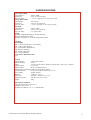
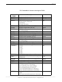
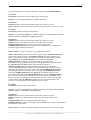
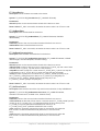
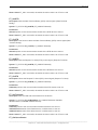
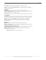
2.3 Commands & Answers description Table
Command
Name
HEADN
SERNU
KEFUN
WSENS
OPDAC
PMSEW
STHFW
HOFTF
ENOMJ
JSENS
ODACJ
EMSEJ
STHEJ
HOFTE
LAMBDA
PNOMW
ZERO
OUTPM
TEMP
WTFIT
VISCA
LEDPRO
Description
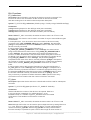
Displays the Head model
Displays the Head serial number
Displays SW measurement’s type:
0: Power Meter (PM) mode
1: FIT Mode
2: Energy (E) Mode
Displays Head sensibility (mV/W)
Displays Output DAC (mV/W)
Displays maximum power value the Head
can withstand (W)
Displays START threshold (W) in FIT mode
Displays FIT inhibition time (sec)
Displays Head nominal energy (J)
Displays Head sensibility (mV/J)
Displays Output DAC (mV/J)
Displays maximum energy value the Head
can withstand (J)
Displays START threshold (J) in E mode
Displays E inhibition time (sec)
Displays selected wavelength:
01: CO2
02: Erb
04: YAG
08: LD
16: VIS
32: EXC
Displays Head nominal power (W)
Arms PLUS in FIT or E mode; zeroing PLUS
in PM mode
Displays measured power/energy (W/J)
Displays Head temperature x 10 (°C)
Displays FIT waiting time (sec)
Displays measured value’s format mode:
0, 1, 2: W for power, J for energy
3, 4, 5: mW for power, mJ for energy
0-3: no decimal point (ex. 10 W/J)
1-4: one decimal number (ex. 10.3 W/J)
2-5: two decimal number (ex. 10.35 W/J)
Displays process parameters state:
1: OFF
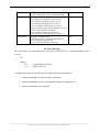
2: OK (min threshold<measured value<max)
Answer
String
Int
Int
Float
Float
Float
Float
Int
Float
Float
Float
Float
Float
Int
Int
Float
“ok”
Float
Int
Int
Int
Int
________________________________________________________________________________
Laserpoint srl – PLUS USB Communication Interface – All Rights Reserved