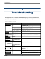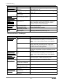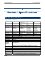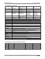
1
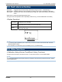
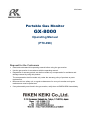
PT0E-0980
Portable Gas Monitor
GX-8000
Operating Manual
(PT0-098)
Request for the Customers
•
•
•
•
•
Read and understand this operating manual before using the gas monitor.
Use the gas monitor in accordance with the operating manual.
Regardless of warranty period, we shall not make any compensation for accidents and
damage caused by using this product.
The compensation shall be made only under the warranty policy of products or parts
replacement.
Because this is a safety unit, a regular maintenance for every six months and regular
maintenance must be performed.
If any abnormality was found in the gas monitor, notify them to RIKEN KEIKI immediately.
Safety information
The Portable Gas Monitor Model GX-8000 is a gas monitor designed to provide continuous exposure
monitoring of combustible gas, oxygen (O2), toxic gas such as carbon monoxide (CO) and hydrogen sulfide
(H2S) in hazardous environments. The gas sample is sucked in by build-in micro pump.
The battery can be selected either Li-ion battery or alkaline dry battery.
Li-ion battery unit is called BUL-8000 and alkaline dry battery unit is called BUD-8000.
The battery unit can be changed even by the end users.
Specification for safety
・Ga Ex ia IIC T4
・
II 1 G Ex ia IIC T4
・Ambient temperature range for use : -20°C to +50°C
・Ambient temperature range during battery charging : 0°C to +40°C
Electrical data
・Power supply of Li-ion battery unit : BUL-8000
Two parallel connected Li-ion cells used in battery pack BP-8000 are from type Maxell
INR18650PB1. Um=250V.
・Power supply of alkaline battery unit : BUD-8000
Powered by three series AA size alkaline batteries , model LR6 by TOSHIBA.
・Backup battery type CR1220 manufactured by Maxell.
Certificate numbers
・IECEx Certificate number :IECEx KEM 10.0038
・ATEX Certificate number :KEMA 10ATEX 0085
List of standards
・IEC 60079-0:2004 ed.4.0
・IEC 60079-11:2006 ed.5.0
・IEC 60079-26:2006 ed.2
・EN60079-0:2006
・EN60079-11:2007
・EN60079-26:2007
WARNING
・Do not charge in hazardous location.
・Do not charge it expect by genuine charger.
・Do not replace battery unit in hazardous location.
・Do not replace dry batteries in hazardous location.
・Do not attempt to disassemble or alter the instrument.
・Use only battery unit type BUD-8000 with three series connected Alkaline
AA batteries, type LR6 manufactured by Toshiba, or use chargeable battery unit
type BUL-8000.
INST. No. 0 0 0 0 0 0 0 0 0 0 0
AB C
D
E
A: Manufacturing year (0-9)
B: Manufacturing month (1-9,XYZ for Oct.-Dec.)
C: Manufacturing lot
D: Serial number
E: Code of factory
2-7-6 Azusawa, Itabashi-ku, Tokyo, 174-8744, Japan
Phone
: +81-3-3966-1113
Fax
: +81-3-3558-9110 GIII
E-mail
: [email protected]
Web site
: http://www.rikenkeiki.co.jp
<Contents>
GX-8000
1
1-1.
1-2.
1-3.
Outline of the Product.............................................................................................. 4
Preface .................................................................................................................... 4
Purpose of use ........................................................................................................ 4
Definition of DANGER, WARNING, CAUTION, and NOTE ..................................... 4
2
2-1.
2-2.
2-3.
Important Notices on Safety .................................................................................... 5
Danger cases .......................................................................................................... 5
Warning cases......................................................................................................... 6
Precautions ............................................................................................................. 7
3
3-1.
3-2.
Product Components............................................................................................... 9
Main unit and standard accessories ........................................................................ 9
Names and functions for each part.......................................................................... 10
4
4-1.
4-2.
4-3.
4-4.
4-5.
4-6.
4-7.
4-8.
4-9.
How to Use.............................................................................................................. 13
Before using the gas monitor................................................................................... 13
Preparation for start-up............................................................................................ 13
Basic operating procedures..................................................................................... 18
How to start the gas monitor.................................................................................... 19
How to detect .......................................................................................................... 21
Modes...................................................................................................................... 25
Air calibration mode................................................................................................. 26
Display/setting mode ............................................................................................... 28
How to exit............................................................................................................... 35
5
5-1.
5-2.
5-3.
Operations and Functions ....................................................................................... 36
Gas alarm activation................................................................................................ 36
Fault alarm activation .............................................................................................. 38
Other functions ........................................................................................................ 38
6
6-1.
6-2.
6-3.
6-4.
Maintenance............................................................................................................ 39
Maintenance intervals and items ............................................................................. 39
Gas calibration method............................................................................................ 40
How to clean............................................................................................................ 41
Parts replacement ................................................................................................... 41
7
7-1.
7-2.
7-3.
Storage and Disposal .............................................................................................. 44
Procedures to store the gas monitor or leave it for a long time ............................... 44
Procedures to use the gas monitor again ................................................................ 44
Disposal of products ................................................................................................ 45
8
Troubleshooting....................................................................................................... 46
9
9-1.
9-2.
Product Specifications ............................................................................................. 48
List of specifications ................................................................................................ 48
List of accessories ................................................................................................... 50
10
Definition of Terms................................................................................................... 51
-3-
1 Outline of the Product
1-1. Preface
1
Outline of the Product
1-1. Preface
Thank you for choosing our portable gas monitor GX-8000. Please check that the model number of the
product you purchased is included in the specifications on this manual.
This manual explains how to use the gas monitor and its specifications. It contains information required for
using the gas monitor properly. Not only the first-time users but also the users who have already used the
product must read and understand the operating manual to enhance the knowledge and experience before
using the gas monitor.
1-2. Purpose of use
This gas monitor is a multi gas type that enables simultaneous monitoring of all of the following five types of
gases at the maximum: oxygen, combustible gases, and toxic gases (carbon monoxide and hydrogen
sulfide) in the air and high-concentration combustible gases (vol%) in N2 and inert gases.
Detection results are not intended to guarantee life or safety in any way.
The gas monitor comes in several types for different combinations of gases to be detected. Check the
specifications of the gas monitor before use and conduct gas detection properly in accordance with
purposes. (See the list of gases to be detected at the end of this operating manual.)
In addition to this operating manual, an operating manual for the data logger management program (option)
is available for the gas monitor. Contact RIKEN KEIKI if it is needed.
1-3. Definition of DANGER, WARNING, CAUTION, and
NOTE
DANGER
This message indicates that improper handling may cause serious damage on
life, health or assets.
WARNING
This message indicates that improper handling may cause serious damage on
health or assets.
CAUTION
This message indicates that improper handling may cause minor damage on
health or assets.
NOTE
GX-8000
This message indicates advice on handling.
-4-
2 Important Notices on Safety
2-1. Danger cases
2
Important Notices on
Safety
2-1. Danger cases
DANGER
About explosion-proof
• Do not modify or change the circuit or structure, etc.
• When measuring the oxygen concentration, do not measure anything but a mixture of air and
combustible gases or vapors and toxic gases.
• When using this gas monitor in a hazardous area, take the following countermeasures for
preventing dangers resulting from electrostatic charges.
(1) Wear anti-static clothes and conductive shoes (anti-static work shoes).
(2) For indoor use, use the gas monitor while standing on a conductive work floor (with a
leakage resistance of 10 MΩ or less).
• The battery units that can be connected are the BUL-8000(G) (certificate number TC19437) or
BUD-8000(G) (certificate number TC19438).
• The specifications of the gas monitor are as follows:
Pump circuit:
Allowable voltage of 4.95 V, allowable current of 1.12 A, and
allowable power of 1138 mW
Combustible gas sensor circuit: Allowable voltage of 4.95 V, allowable current of 0.834 A, and
allowable power of 853 mW
Buzzer circuit:
Allowable voltage of 4.95 V, allowable current of 0.431 A, and
allowable power of 441 mW
Main circuit:
Allowable voltage of 4.95 V, allowable current of 0.717 A, and
allowable power of 733 mW
Backup circuit:
3.0 VDC, 10 µA
About use
• While conducting measurement in a manhole or confined space, do not lean over or look into the
manhole or closed space. It may lead to dangers because oxygen-deficient air or other gases
may blow out.
• Oxygen-deficient air or other gases may blow out from the gas exhausting outlet. Never inhale
the air or gases.
• High-concentration (more than LEL) gases may blow out. Never use fire near the gas monitor.
-5-
GX-8000
2 Important Notices on Safety
2-2. Warning cases
2-2. Warning cases
WARNING
Sampling point pressure
• The gas monitor is designed to draw gases around it under the atmospheric pressure. If
excessive pressure is applied to the gas inlet and outlet (GAS IN, GAS OUT) of the gas monitor,
detected gases may be leaked from its inside, thus leading to dangers. Be sure that excessive
pressure is not applied to the gas monitor while used.
• Do not connect the gas sampling hose directly to a location with a pressure higher than the
atmospheric pressure. The internal piping system may be damaged.
Handling of sensor
Do not disassemble the electrochemical type sensor or galvanic cell type sensor because they
contain electrolyte. Electrolyte may cause severe skin burns if it contacts skin, while it may cause
blindness if it contacts eyes.
If electrolyte is adhered on your clothes, that part on your clothes is discolored or its material is
decomposed. If contact occurs, rinse the area immediately with a large quantity of water.
Fresh air adjustment in atmosphere
When the fresh air adjustment is performed in the atmosphere, check the atmosphere for freshness
before beginning the adjustment. If other gases exist, the adjustment cannot be performed properly,
thus leading to dangers when the gas leaks.
Response to gas alarm
Issuance of a gas alarm indicates that there are extreme dangers. Take proper actions based on
your judgment.
Battery level check
• Before use, check that there remains sufficient battery power. When the gas monitor is used for
the first time or is not used for a long period, the batteries may be exhausted. Either fully
recharge the batteries or replace them with new ones before use.
• If a low battery voltage alarm occurs, gas detection cannot be conducted. If the alarm occurs
during use, turn off the power and promptly recharge the batteries in a non-hazardous area.
Others
• Do not throw the gas monitor into fire.
• Do not wash the gas monitor in a washing machine or ultrasonic cleaner.
• Do not block the buzzer sound opening. No alarm sound can be heard.
• Do not remove the battery unit while the power is ON.
GX-8000
-6-
2 Important Notices on Safety
2-3. Precautions
2-3. Precautions
CAUTION
Do not use the gas monitor where it is exposed to oil, chemicals, etc. Do not submerge the gas
monitor under water on purpose.
• Do not use in a place where the gas monitor is exposed to liquids such as oil and chemicals.
• The gas monitor, being compliant to IP67, is not water-pressure-resistant. Do not use the gas
monitor where a high water pressure is applied to it (under a faucet, shower, etc.) or submerge it
under water for a long time. The gas monitor is water-proof only in fresh water and running
water, and not in hot water, salt water, detergent, chemicals, human sweat, etc.
• The gas inlet and outlet are not water-proof. Be careful not to let water such as rainwater get into
these parts. Because this may cause trouble and gas cannot be detected.
• Do not use the gas monitor where water or dirt gets accumulated. The gas monitor placed at
such a location may malfunction due to water or dirt that gets into the buzzer opening, gas inlet,
etc.
• Note that drawing in dirty water, dust, metallic powder, etc. will significantly deteriorate the
sensor sensitivities. Be careful when the gas monitor is used in an environment where these
elements exist.
Do not use the gas monitor in a place where the temperature drops below -20ºC or rises over 50ºC.
• The operating temperature of the gas monitor is -20 to 50ºC. Do not use the gas monitor at
higher temperatures, humidities, and pressures or at lower temperatures than the operating
range.
• Avoid long-term use of the gas monitor in a place where it is exposed to direct sunlight.
• Do not store the gas monitor in a sun-heated car.
Observe the operating restrictions to prevent condensation inside the gas monitor or gas sampling
hose.
Condensation formed inside the gas monitor or gas sampling hose causes clogging or gas
adsorption, which may disturb accurate gas detection. Thus, condensation must be avoided. In
addition to the operating environment, carefully monitor the temperature/humidity of the sampling
point to prevent condensation inside the gas monitor or gas sampling hose. Please observe the
operating restrictions.
Do not use a transceiver near the gas monitor.
• Radio wave from a transceiver near the gas monitor may disturb readings. If a transceiver is
used, it must be used in a place where it disturbs nothing.
• Do not use the gas monitor near a device that emits strong electromagnetic waves
(high-frequency or high-voltage devices).
Verify that the pump driving indicator is rotating before using the gas monitor.
If the pump driving indicator is not rotating, gas detection cannot be performed properly. Check
whether the flow rate is lost.
Do not forget to perform a regular maintenance.
Since this is a safety unit, a regular maintenance must be performed to ensure safety. Continuing to
use the gas monitor without performing a maintenance will compromise the sensitivity of the sensor,
thus resulting in inaccurate gas detection.
-7-
GX-8000
2 Important Notices on Safety
2-3. Precautions
CAUTION
Others
• Pressing buttons unnecessarily may change the settings, preventing alarms from activating
correctly. Operate the gas monitor using only the procedures described in this operating manual.
• Do not drop or give shock to the gas monitor. The water-proof and explosion-proof properties
and accuracy may be deteriorated.
• Do not use the gas monitor while recharging it.
• Whereas the gas monitor can detect oxygen, combustible gases, carbon monoxide, and
hydrogen sulfide, the operating environment may include gases that have harmful effects on the
sensors of this unit. (Different gases can be defected depending on the type.)
The gas monitor cannot be used in the presence of the following gases:
(1) Sulfides (such as H2S and SO2) continuously existing in high concentrations
(2) Halogen gases (such as chloride compounds and chlorofluorocarbons)
(3) Silicone (Si compounds)
Do not use the gas monitor in the presence of the above gases (such as high-concentration
sulfides, halogen gases, and silicone), which may shorten the sensor life significantly or cause
malfunctions such as inaccurate readings.
In case the gas monitor is used for detection in the presence of silicone, etc., be sure to check
the gas sensitivities before using it again.
GX-8000
-8-
3 Product Components
3-1. Main unit and standard accessories
3
Product Components
3-1. Main unit and standard accessories
After opening the package, check the main unit and accessories.
If anything in the following list is not included, contact RIKEN KEIKI.
<Main Unit>
GX-8000
main unit
<Standard Accessories>
• AC powered charger: 1
• Gas sampling probe and
gas sampling hose: 1
• Shoulder strap: 1
Li-ion battery unit
• Operating manual
• Product warranty
DANGER
About explosion-proof
• Do not modify or change the circuit or structure, etc.
• When measuring the oxygen concentration, do not measure anything but a mixture of air and
combustible gases or vapors and toxic gases.
• When using this gas monitor in a hazardous area, take the following countermeasures for
preventing dangers resulting from electrostatic charges.
(1) Wear anti-static clothes and conductive shoes (anti-static work shoes).
(2) For indoor use, use the gas monitor while standing on a conductive work floor (with a
leakage resistance of 10 MΩ or less).
• The battery units that can be connected are the BUL-8000(G) (certificate number TC19437) or
BUD-8000(G) (certificate number TC19438).
• The specifications of the gas monitor are as follows:
Pump circuit:
Allowable voltage of 4.95 V, allowable current of 1.12 A, and
allowable power of 1138 mW
Combustible gas sensor circuit: Allowable voltage of 4.95 V, allowable current of 0.834 A, and
allowable power of 853 mW
Buzzer circuit:
Allowable voltage of 4.95 V, allowable current of 0.431 A, and
allowable power of 441 mW
Main circuit:
Allowable voltage of 4.95 V, allowable current of 0.717 A, and
allowable power of 733 mW
Backup circuit:
3.0 VDC, 10 µA
-9-
GX-8000
3 Product Components
3-2. Names and functions for each part
NOTE
There are the following two combinations of
battery units. The following information is printed
on the battery unit for the sake of identification to
prevent a mistake in combinations.
• BUL-8000 (certification number TC19437)=>
BUL-8000(G)
• BUL-8000 (certification number TC19438)=>
BUD-8000(G)
Additionally, a nameplate indicating a compatible
model is affixed on the top of the battery unit.
Check this information and use a correct
combination.
Printing for
identification
3-2. Names and functions for each part
<Outline Drawing>
GX-8000
- 10 -
3 Product Components
(1)
(2)
(3)
(4)
LCD display
Buzzer sound opening
Alarm LED arrays
Infrared communication port
(5)
(6)
(7)
(8)
(9)
(10)
(11)
▲/AIR switch
▼/RESET switch
DISPLAY switch
POWER/ENTER switch
Gas inlet
Gas outlet
Recharging jack cover
(12) Recharging indicator lamp
(13) Sensor cover
(14) Activated carbon filter knob
(15) Battery unit screws
3-2. Names and functions for each part
Displays gas concentrations, alarms, etc.
Emits a buzzer sound at an alarm. (Do not block it.)
The lamp blinks in response to an alarm.
Used to carry out data communications with a PC in data logger
mode.
Keep this switch pressed to perform fresh air adjustment.
When an alarm occurs, press this switch to reset the alarm.
Press this switch to change between display modes.
Turns on and off the power.
Connect a sampling hose to this port.
Exhausts the gas drawn into the gas monitor. (Do not block it.)
Remove this cover to connect an AC powered charger and recharge
the batteries.
Lights up in red during recharging and goes off when recharging is
completed.
There are sensors inside. May be opened only when the sensor is to
be replaced.
Turn this knob to detach and replace the activated carbon filter. No
activated carbon filter is used on a type that does not measure carbon
monoxide. Keep this knob tightened at all times.
Turn these screws to detach and replace the battery unit.
CAUTION
• Do not jab the buzzer opening with a sharp-pointed item. The unit may malfunction or get
damaged, allowing water or foreign substance, etc. to get inside.
• Do not remove the panel sheet on the display. The water-proof and dust-proof performances will
be deteriorated.
• Do not affix a label on the infrared port. Infrared communications can no longer be conducted.
- 11 -
GX-8000
3 Product Components
3-2. Names and functions for each part
<LCD Display>
(1) Pilot indicator
(5) Pump driving
indicator
(2) Combustible gas
concentration digital
and bar display
(6) Oxygen
concentration digital
and bar display
(3) Carbon monoxide
concentration digital
and bar display
(7) Hydrogen sulfide
concentration digital
and bar display
(4) Battery level icon
(8) Clock display
(1)
(2)
(3)
(4)
(5)
(6)
(7)
(8)
Pilot indicator
Combustible gas
concentration
digital and bar display
Carbon monoxide
concentration
digital and bar display
Battery level display
Pump driving indicator
Oxygen concentration
digital and bar display
Hydrogen sulfide
concentration
digital and bar display
Clock display
Displays the operating status in the detection mode. Normal: Blinking
Displays the gas concentration as a numeric value and a level in the bar
graph.
Displays the gas concentration as a numeric value and a level in the bar
graph.
Displays the battery level. See the information below for the meanings of
battery level icons.
Displays the suction status in the detection mode. Normal: Rotating
Displays the gas concentration as a numeric value and a level in the bar
graph.
Displays the gas concentration as a numeric value and a level in the bar
graph.
Displays the current time.
NOTE
The meanings of battery level icons are as follows:
: Sufficient /
: Low /
: Needs recharging
If the battery level is lower than the above, the inside of the battery icon starts to blink (
GX-8000
- 12 -
).
4 How to Use
4-1. Before using the gas monitor
4
How to Use
4-1. Before using the gas monitor
Not only the first-time users but also the users who have already used the product must follow the operating
precautions.
Ignoring the precautions may damage the gas monitor, resulting in inaccurate gas detection.
4-2. Preparation for start-up
Before starting gas detection, read and understand the following precautions. Ignoring these precautions
may prevent correct gas detection.
•
•
•
•
Check that the battery level is sufficient.
Check that there is no bend or hole in the gas sampling hose.
Check that the filter in the gas sampling probe is free of dust or clogging.
Check that the gas monitor, gas sampling probe, and gas sampling hose are connected properly.
<Recharging of Batteries>
When the gas monitor is used for the first time, or when the battery level is low, be sure to use the
accessory AC powered charger to recharge the batteries.
•
•
•
•
CAUTION
Use the dedicated AC powered charger.
Recharge the batteries in a non-hazardous area.
Recharge the batteries at ambient temperatures between 0 to 40ºC.
Do not use the gas monitor while recharging it. Correct measurements cannot be obtained.
Furthermore, the batteries get deteriorated more quickly and may have a shorter life.
• The AC powered charger is not water-proof or dust-proof. Do not recharge the batteries while the
gas monitor is wet.
• The AC powered charger is not explosion-proof.
- 13 -
GX-8000
4 How to Use
4-2. Preparation for start-up
(1) Open the recharging jack cover of the gas monitor.
CAUTION
Do not pull the recharging jack cover too hard.
It may get damaged.
(2) Put the plug of the AC powered charger into the recharging jack of
the gas monitor.
(3) Connect the AC powered charger to the wall electric outlet.
When recharging is started, the recharging indicator lamp lights up
(red).
(Recharging time: Three hours at the maximum until the batteries are fully recharged)
(4) When recharging is completed, the recharging indicator lamp goes off.
(5) When recharging is completed, disconnect the AC powered charger from the wall electric outlet.
(6) Pull out the AC powered charger plug from the power jack of the gas monitor and reattach the
recharging jack cover. Put the recharging jack cover as far as it will go.
CAUTION
• Do not use the gas monitor with the recharging jack cover detached. Dust or water may get into
the gas monitor, causing it to malfunction. Replace the recharging jack cover if it is damaged.
• If the recharging jack cover is not completely closed, water may get in from the power jack. The
same thing occurs if a minute foreign substance is caught beneath the cover.
• Disconnect the AC powered charger from the wall electric outlet while it is not in use.
NOTE
• During recharging, the battery pack may get hot, but this is not abnormal.
• The temperature of the gas monitor is high immediately after recharging is completed. Let it leave for
10 minutes or more before using it. Otherwise, correct measurements may not be obtained.
• When fully recharged batteries are recharged again, the recharging indicator lamp does not go on.
GX-8000
- 14 -
4 How to Use
4-2. Preparation for start-up
<Attaching Batteries> (when the optional unit BUD-8000(G) is used)
When the gas monitor is used for the first time, or when the battery level is low, attach new AA alkaline
batteries.
CAUTION
<Replacement>
• Turn off the power of the gas monitor before replacing the batteries.
• Replace the batteries in a non-hazardous area.
• Replace all of the three batteries with new ones at one time.
• Pay attention to the polarities of the batteries.
• If the battery cover fixing screw is not completely tightened, the dry batteries may drop off or
water may get in through the clearance. Water may also get in if a minute foreign substance is
caught beneath the battery unit.
<Batteries>
• Use AA alkaline batteries.
Rechargeable batteries cannot be used.
(1) Using a flathead screwdriver or coin, turn the battery
cover fixing screw counterclockwise to open the
battery cover.
(2) Paying attention to the polarities of batteries, replace
all the three batteries with new ones.
(3) Close the battery cover and tighten the battery cover
fixing screw.
- 15 -
GX-8000
4 How to Use
4-2. Preparation for start-up
<Detaching Battery Unit>
(1) Loosen the two battery unit screws.
(They need not be completely detached.)
(2) Detach the battery unit.
(3) Attach a new battery unit.
NOTE
Make sure that the battery unit is installed in
correct orientation by checking the locations of the
connection terminal and projection portions.
(4) Securely tighten the two battery unit screws.
CAUTION
• Turn off the power of the gas monitor before
replacing the battery unit.
• Detach and reattach the battery unit in a
non-hazardous area.
• If the battery unit screw is not completely
tightened, the battery unit may drop off or
water may get in through the clearance.
Water may also get in if a minute foreign
substance is caught beneath the battery
unit.
• Do not damage the rubber seal.
• To maintain the water-proof and dust-proof
performances, it is recommended to replace
the rubber seal every two years, whether or
not it has an abnormality.
GX-8000
- 16 -
4 How to Use
4-2. Preparation for start-up
<Connection of Gas Sampling Probe and Gas Sampling Hose>
• Attach the gas sampling probe to the end of the gas sampling hose.
• Connect the sampling hose securely to the gas inlet (GAS IN) of the gas monitor.
Insert the sampling hose to the gas inlet (GAS IN) until it clicks into
place to ensure connection.
CAUTION
• Use only a gas sampling hose specified by RIKEN KEIKI.
• Use the gas monitor with the gas sampling probe connected so that no foreign substance is
drawn into it.
• Connect a gas sampling probe and a gas sampling hose by fastening them manually without
using any tool. If they are fastened too tightly using a tool, the plastic part of the gas sampling
probe may be broken.
- 17 -
GX-8000
4 How to Use
4-3. Basic operating procedures
4-3. Basic operating procedures
Normally, the detection mode is used for normal operations. (The detection mode is activated after the
power is turned on.)
<<Detection Mode>>
RESET
AIR (long pressing)
<<Gas Alarm Status>>
(Self-latching <Reset after
Recovery to Normal Status>)
<<Air Calibration Mode>>
DISPLAY
<<Fault Alarm Status>>
<<Display and Setting Mode>>
(Self-latching)
GX-8000
- 18 -
4 How to Use
4-4. How to start the gas monitor
4-4. How to start the gas monitor
<<Start-up Procedure>>
Keep the POWER switch pressed for three seconds or more.
↓
LCD
Alarm lamp lights up.
Buzzer sounds once. (Beep)
All LCDs light up.
↓
Date/Time Display
↓
Battery Voltage Display
↓
Gas Name Display
↓
Full Scale Display
↓
First Alarm Setpoint Display
↓
Second Alarm Setpoint Display
- 19 -
GX-8000
4 How to Use
4-4. How to start the gas monitor
↓
STEL Alarm Setpoint Display
↓
TWA Alarm Setpoint Display
↓
ID Display
↓
Buzzer sounds twice. (Beep, beep)
Detection Mode
CAUTION
After start-up, perform air calibration before performing gas detection (air calibration mode).
NOTE
• A sensor abnormality alarm is issued before the detection mode is entered if there is any abnormality
in the sensor. Press the RESET button. This will reset the sensor abnormality alarm temporarily, set
the gas concentration display that was abnormal on the sensor to ---, and start gas detection. However,
notify the abnormality to RIKEN KEIKI promptly. Gas for which there was an abnormality in the sensor
cannot be detected. However, the alarm cannot be reset if there is an abnormality in all the sensors.
• If there is an abnormality in the built-in clock, a fault alarm FAIL CLOCK may be issued. Press the
RESET button. The fault alarm is temporarily reset, and measurement is started with incorrect clock
time.
GX-8000
- 20 -
4 How to Use
4-5. How to detect
4-5. How to detect
In the detection mode, put the gas sampling probe close to the detection area and take the reading on the
display.
Display example
<- Display example
CH4 concentration:
O2 concentration:
CO concentration:
H2S concentration:
Time:
Battery level:
0%LEL
20.9%
0 ppm
0 ppm
9:30
Sufficient
DANGER
• While conducting measurement in a manhole or confined space, do not lean over or look into the
manhole or closed space. It may lead to dangers because oxygen-deficient air or other gases
may blow out.
• Oxygen-deficient air or other gases may blow out from the gas exhausting outlet. Never inhale
the air or gases.
• High-concentration (more than LEL) gases may blow out. Never use fire near the gas monitor.
WARNING
• The gas monitor is designed to draw gases around it under the atmospheric pressure. If
excessive pressure is applied to the gas inlet and outlet (GAS IN, GAS OUT) of the gas monitor,
detected gases may be leaked from its inside, thus leading to dangers. Be sure that excessive
pressure is not applied to the gas monitor while used.
• Do not connect the sampling hose directly to a location with a pressure higher than the
atmospheric pressure. The internal piping system may be damaged.
• When the fresh air adjustment is performed in the atmosphere, check the atmosphere for
freshness before beginning the adjustment. If other gases exist, the adjustment cannot be
performed properly, thus leading to dangers when the gas leaks.
• Issuance of a gas alarm indicates that there are extreme dangers. Take proper actions based on
your judgment.
• Before use, check that there remains sufficient battery power. When the gas monitor is used for
the first time or is not used for a long period, the batteries may be exhausted. Either fully
recharge the batteries or replace them with new ones before use.
• If a low battery alarm occurs, gas detection cannot be conducted. If the alarm occurs during use,
turn off the power and promptly recharge the batteries in a non-hazardous area.
• Do not block the buzzer sound opening. No alarm sound can be heard.
- 21 -
GX-8000
4 How to Use
4-5. How to detect
CAUTION
• Before performing gas detection, attach the gas sampling probe provided with the gas monitor to
prevent disturbances by air dust.
• When you measure concentrations of oxygen in inert gases for a long time, the carbon dioxide
concentration in the air must be 15% or less. When you use the gas monitor in the air with a
carbon dioxide concentration of 15% or higher, perform measurement in as short time as
possible. Using the gas monitor under high concentrations for a long time may shorten the life of
the oxygen sensor.
• An oxygen concentration higher than a certain level is required for the combustible gas %LEL
sensor of the gas monitor to correctly detect gases and display concentrations.
• During combustible gas detection (%LEL range), long-time detection of a high-concentration
combustible gas may adversely influence the sensor.
• Use the gas monitor with the LCD display facing upward. The gas monitor, when used with the
LCD display in a tilted or flat status, may not display correct values.
NOTE
• If the combustible gas reading exceeds 100% LEL, the CO reading rises temporarily but this is not
abnormal.
• In a low-temperature environment, the operating time is shortened due to the battery performance
property.
• At a low temperature, the response of the LCD display may get slow down.
• If a combustible gas with a higher concentration than %LEL is drawn, some gas may remain in the gas
sampling hose due to adsorption in the hose, gas sampling probe, etc. After drawing a
high-concentration combustible gas, clean the gas monitor to remove the adsorbed gas (draw fresh air
and check that the reading becomes zero).
Performing fresh air adjustment before cleaning it completely will result in inaccurate adjustment,
giving adverse influence on measurement. In such a case, remove the gas sampling hose before
performing fresh air adjustment to avoid inaccurate adjustment.
• Perform gas detection in the vol% range (Type-A and E only) in a place where the presence of a
high-concentration combustible gas is known.
NOTE
<Influence of Coexisting Gases on High-Concentration Combustible Gas Sensor> (TYPES-A and E Only)
A thermal-conductivity sensor that detects high-concentration combustible gases, based on the principle
of detection using a difference in thermal conductivities of gases, may display a reading that is disturbed
by a considerable change in the concentration of gases other than the combustible gases that coexist in
the atmosphere.
However, the influence of oxygen on readings can be automatically corrected by the sensor, which
detects oxygen at the same time, by feeding back a change in the oxygen concentration to the detection
result of high-concentration combustible gases.
If coexisting gases other than oxygen undergo a high concentration change, the influence from the
change cannot be automatically corrected. This sensor is adjusted to be able to detect high-concentration
combustible gases in the air as well as in an nitrogen atmosphere. If the composition of the atmosphere
other than nitrogen is known in advance, adjusting the sensor in accordance with the atmosphere can
alleviate influences on readings. For information on the adjustment procedure, see the separate
"Maintenance Manual."
GX-8000
- 22 -
4 How to Use
4-5. How to detect
<Manual Memory>
Any instantaneous value during measurement can be recorded.
Up to 256 points of data can be recorded. When the number of recorded data points reaches the maximum,
recorded data will be overwritten, starting from the oldest data.
(1) In the detection mode, keep the ▼/RESET switch pressed and press the ▲/AIR switch to prepare for
recording (about one second). The following screens are displayed in turn on the gas monitor.
NOTE
The screen displays the memory number, date, and instantaneous value in turn. Go to the next step to
execute recording. No value is recorded at this point yet. If you do not want to record a value, press the
DISPLAY switch to return to the detection mode.
(2) Press the ENTER switch. The date and the instantaneous value at the time when the ENTER switch is
pressed are recorded.
(3) When END is displayed, the recording is completed.
Returns to the detection mode.
- 23 -
GX-8000
4 How to Use
4-5. How to detect
<Auto Range Switching Point> (TYPES-A and E Only)
If Auto Range is set on a type with the vol% range for combustible gases, the display is automatically
switched to the vol% range when the concentration of a detected combustible gas exceeds 100%LEL.
When the concentration drops, the display returns to the %LEL range again. The following shows an
example of switching timing.
Diagram of gas concentrations and range switching timing under Auto Range setting
CH4concentration
5 vol%
(100%LEL)
3 vol%
(60%LEL)
%LEL range
vol% range
Switching point
%LEL range
Switching point
CAUTION
An oxygen concentration higher than a certain level is required for the combustible gas %LEL
sensor of the gas monitor to correctly detect gases and display concentrations. For the sake of more
accurate gas detection and concentration display, therefore, this gas sensor may perform detection
using the vol% sensor if the built-in oxygen sensor of this unit detects an oxygen concentration
lower than a certain level in the atmosphere.
In other words, the display changes at the timing shown above when the oxygen concentration is
equal to or higher than a certain level. If it is lower than a certain level, however, the vol% sensor is
used for detection even if the combustible gas concentration is lower than the switching point.
GX-8000
- 24 -
4 How to Use
4-6. Modes
4-6. Modes
Details on each mode are provided as follows. (* Operations are slightly different depending on the type.)
Mode
Item
LCD display
Details
Detection
―
Concentration display
Normal state
Mode
Air Calibration
Mode
―
AIR CAL
Perform the zero adjustment.
Display and
Setting Mode
Combustible
Gas
Measurement
Range Setting
HC RANGE
Used to select a combustible gas
measurement range manually.
(TYPES-A and E only)
Peak Display
PEAK
Display the maximum concentration (or
minimum concentration for oxygen)
detected during measurement from
power-on to the present.
STEL Value
Display
STEL
Display the STEL value after power-on.
(TYPES-A, B, C, and D only)
TWA Value
Display
TWA
Display the TWA value after power-on.
(TYPES-A, B, C, and D only)
Alarm Setpoint ALARM-P
Display
Alarm Test
Display the full scale and alarm setpoint
values and check the alarm operations for
the settings displayed.
Pump
ON/OFF
Setting
PUMP OFF
Used to turn on/off the pump operations.
ID Setting
ID SELECT
Display an ID if it has been set in advance.
Also used to change or set an ID.
Log Data
Display
REC.DATA
Display data recorded to the manual
memory.
- 25 -
GX-8000
4 How to Use
4-7. Air calibration mode
4-7. Air calibration mode
Press the AIR switch.
Keep pressing the AIR switch.
Changes the display to Adj HOLD AIR.
When RELEASE is displayed,
release the AIR switch.
A 30-second countdown is
started on the LCD.
(TYPES-A and E only)
When the zero adjustment is
successfully completed, END
is displayed, and you return to
the detection mode.
WARNING
When air calibration is performed in the atmosphere, check the atmosphere for freshness before
beginning the calibration. If other gases exist, the adjustment cannot be performed properly, thus
leading to dangers when the gas leaks.
CAUTION
• Perform air calibration under pressure and temperature/humidity conditions close to those in the
operating environment and in fresh air.
• Perform air calibration after the reading is stabilized.
• If there is a sudden temperature change of 15°C or more between the storage and operation
locations, turn on the power of the gas monitor, let it leave for about 10 minutes in a similar
environment to the operation location, and perform air calibration in fresh air before using it.
GX-8000
- 26 -
4 How to Use
4-7. Air calibration mode
NOTE
• Air calibration can be performed even when there is a gas alarm.
• If the air calibration fails, it displays "FAIL" - "AIR CAL" and which sensor
has become faulty. Press the RESET button to reset the fault alarm
(calibration failure). When the alarm is reset, the value before calibration is
displayed.
If CH4 sensor is faulty
- 27 -
GX-8000
4 How to Use
4-8. Display/setting mode
4-8. Display/setting mode
This mode allows you to change various displays and settings.
Every time the DISPLAY switch is pressed, various screens are displayed in turn.
(* Operations are slightly different depending on the type.)
LCD
Detection Mode
Display and Setting Mode
Combustible Gas Measurement
ENTER Range Setting
⇒ P30
Combustible Gas Measurement
Range Setting
Used to select a combustible gas
measurement range manually.
(TYPES-A and E only)
PEAK
Display the maximum
concentration (or minimum
concentration for oxygen)
detected during measurement
from power-on to the present.
STEL
Display the STEL value after
power-on.
(TYPES-A, B, C, and D only)
TWA
Display the TWA value after
power-on.
(TYPES-A, B, C, and D only)
Full Scale Display/Alarm Setpoint
ENTER Display/Alarm Test
⇒ P32
Full Scale Display/Alarm
Setpoint Display/Alarm Test
Display the full scale and alarm
setpoint values and check the
alarm operations for the settings
displayed.
GX-8000
- 28 -
4 How to Use
4-8. Display/setting mode
Pump ON/OFF Setting
Used to turn on/off the pump
operations.
ID Display/Selection
Display an ID if it has been
registered in advance. Also used
to select an ID.
Log Data Display
Display concentration data
recorded to the manual memory.
ENTER
Pump ON/OFF Setting
⇒ P33
ENTER
ID Display/Selection
⇒ P34
ENTER
Log Data Display
⇒ P35
To Detection Mode
NOTE
The gas monitor automatically returns to the detection mode in about 20 seconds if the gas monitor is left
unoperated.
However, the gas monitor does not automatically return to the detection mode if the pump operation is set
to OFF.
- 29 -
GX-8000
4 How to Use
4-8. Display/setting mode
<Combustible Gas Measurement Range Setting "HC RANGE"> (TYPES-A and E Only)
The models that can display combustible gas levels in two ways, "%LEL range" and "vol% range,"
automatically switch between these two displays according to the gas concentration or oxygen
concentration, from "%LEL range" to "vol% range" and vice versa. They also support manual selection of
measurement range.
(1) Press the DISPLAY switch and select the combustible gas measurement range setting from the
display/setting mode menu.
The following screens are displayed in turn on the gas monitor.
(2) Press the ENTER switch.
NOTE
If you do not want to make a change, press the DISPLAY switch to return to the display/setting mode
menu.
(3) Every time the ▲ or ▼ switch is pressed, the measurement range menus, AUTO RANGE (automatic
switching), ONLY VOL (fixed to the vol% range), and ONLY LEL (fixed to the %LEL range), are
displayed in turn.
Press the ▲ or ▼ switch to select a measurement range and press the ENTER switch.
(4) When END is displayed, the setting is completed.
The display/setting mode menu is displayed again.
(5) After completion, press the DISPLAY switch several times until it returns to the detection mode.
GX-8000
- 30 -
4 How to Use
4-8. Display/setting mode
CAUTION
• No gas alarm is triggered in the combustible gas vol% range-only setting.
In the vol% range-only setting, the screen displays [No ALARM] because no alarm is triggered.
• Be careful because the %LEL range-only setting screen does not appear different from the auto
range setting screen.
Even if the concentration exceeds the full scale, the screen does not automatically switch to the
vol% range.
No ALARM display
vol% range only
%LEL range only
NOTE
During vol% range-only measurement, "vol%" and "No ALARM" displays blink.
- 31 -
GX-8000
4 How to Use
4-8. Display/setting mode
<Full Scale Display/Alarm Setpoint Display/Alarm Test "ALARM-P">
Display the full scale or alarm setpoint values and check the alarm operations for the settings displayed.
(1) Press the DISPLAY switch and select the "full scale display/alarm setpoint display/alarm test" from the
display/setting mode menu. The following screens are displayed in turn on the gas monitor.
(2) Press the ENTER switch to enter the alarm setpoint or other display.
NOTE
If you do not want to enter any display, press the DISPLAY switch to return to the display/setting mode
menu.
(3) Every time the ▲ or ▼ switch is pressed, the full scale and alarm setpoint menus, i.e., full scale display,
first alarm setpoint display, second alarm setpoint display, STEL alarm setpoint display, and TWA
alarm setpoint display, are displayed in turn.
Press either the ▲ or ▼ switch to select a setting that you want to check.
Select one of the following screens:
Full Scale Display
First Alarm Setpoint Display
(WARNING)
Second Alarm Setpoint Display
(ALARM)
STEL Alarm Setpoint Display (*)
TWA Alarm Setpoint Display(*)
* TYPES-A, B, C, and D only
(4) Press the ENTER switch to perform alarm test. The alarm operation on this screen can be checked.
Press any switch to stop the alarm operation.
(5) Press the DISPLAY switch to exit the alarm setpoint display or alarm test. The display/setting mode
menu is displayed again.
(6) After completion, press the DISPLAY switch several times until it returns to the detection mode.
GX-8000
- 32 -
4 How to Use
4-8. Display/setting mode
<Pump ON/OFF Setting "PUMP OFF">
Used to turn on/off the pump operations.
CAUTION
• While the pump operation is set to OFF, no gas detection is performed because no gas is drawn.
• The gas monitor does not automatically return to the detection mode if the pump operation is set
to OFF.
(1) Press the DISPLAY switch and select the pump ON/OFF setting from the display/setting mode menu.
The following screens are displayed in turn on the gas monitor.
(2) Press the ENTER switch to set the pump operation to ON or OFF.
NOTE
If you do not want to set the pump operation or ON or OFF, press the DISPLAY switch to return to the
display/setting mode menu.
(3) Every time the ENTER switch is pressed, the pump operation is turned ON or OFF.
Pump ON
Pump OFF
NOTE
While the pump operation is set to OFF, only the ENTER switch is enabled.
(4) To return to the detection mode, press the ENTER switch to set the pump operation to ON.
(5) After completion, press the DISPLAY switch several times until it returns to the detection mode.
- 33 -
GX-8000
4 How to Use
4-8. Display/setting mode
<ID Display/Selection "ID SELECT">
Display an ID if it has been registered in advance. Also used to select an ID.
(1) Press the DISPLAY switch and select the ID display/selection from the display/setting mode menu.
The following screens are displayed in turn on the gas monitor.
(2) Press the ENTER switch to set or select an ID.
NOTE
• If you do not want to set or select an ID, press the DISPLAY switch to return to the display/setting
mode menu.
• On this gas monitor, either of the IDs from ST-ID000 to ST-ID255 has been registered, unless
otherwise specified.
• The data logger management program (option) is required to register or change an ID. Please contact
RIKEN KEIKI.
(3) Press either the ▲ or ▼ switch to select an ID.
Every time the ▲ or ▼ switch is pressed, the ID number increases or decreases (000-255).
(4) Press the ENTER switch.
(5) When END is displayed, the setting is completed.
The display/setting mode menu is displayed again.
(5) After completion, press the DISPLAY switch several times until it returns to the detection mode.
GX-8000
- 34 -
4 How to Use
4-9. How to exit
<Log Data Display "REC.DATA">
Display concentration data recorded to the manual memory.
(1) Press the DISPLAY switch and select the log data display from the display/setting mode menu.
The following screens are displayed in turn on the gas monitor.
(2) Press the ENTER switch to display the log data.
NOTE
If you do not want to display the log data, press the DISPLAY switch to return to the display/setting mode
menu.
(3) Every time the ▲ or ▼ switch is pressed, the log data menus are displayed in turn.
Press either the ▲ or ▼ switch to select log data that you want to check. The log data menu displays
the year, month, day, time, and memory number.
(4) Press the ENTER switch to display the selected log data.
(5) If you want to display other log data, press the ENTER switch to return to the log data menu. Repeat
the steps (3) to (5).
(6) After completion, press the DISPLAY switch to return to the detection mode.
4-9. How to exit
Make the gas monitor draw in fresh air. After the display returns to zero (or 20.9% for oxygen), keep the
POWER/ENTER switch pressed until the power is turned off.
NOTE
If the display is not zero (or 20.9% for oxygen) when the power is turned off, a
purge operation may be performed for 30 seconds at the maximum to clean the
inside of the gas monitor.
- 35 -
GX-8000
5 Operations and Functions
5-1. Gas alarm activation
5
Operations and Functions
5-1. Gas alarm activation
Gas alarm:
Triggered when the concentration of detected gas reaches or exceeds the alarm setpoint
value. <<Self-latching>>
Alarm display: Notified by blinking of a gas concentration value display, sounding of the buzzer, and lighting
of the lamp.
Alarm types: First alarm (WARNING), second alarm (ALARM), OVER alarm, TWA alarm, and STEL alarm
<List of Gas Alarms>
Alarm type
Oxygen
Combustible
gas
Hydrogen
sulfide
Carbon
monoxide
Buzzer
Alarm lamp
LCD display
GX-8000
First alarm
18.0%
(Japanese
specification)
19.5%
(Overseas
specification)
10%LEL
Second alarm
25.0%
(Japanese
specification)
23.5%
(Overseas
specification)
50%LEL
OVER alarm
40.0%
TWA alarm
STEL alarm
⎯
⎯
100%LEL
⎯
⎯
5.0 ppm
30.0 ppm
100.0 ppm
10.0 ppm
15.0 ppm
25 ppm
50 ppm
500 ppm
25 ppm
200 ppm
Repeatedly
sounds strong
and weak beeps
at about one
second
intervals:
Beep, beep
Repeatedly
blinks at about
one second
intervals.
Gas
concentration
and
WARNING
display blink.
Repeatedly
sounds strong
and weak
beeps at about
0.5 second
intervals:
Blip, blip
Repeatedly
blinks at about
0.5 second
intervals.
Gas
concentration
and
ALARM display
blink.
Repeatedly
sounds strong
and weak beeps
at about 0.5
second intervals:
Blip, blip
Repeatedly
sounds strong
and weak beeps
at about one
second
intervals:
Beep, beep
Repeatedly blinks Repeatedly
at about 0.5
blinks at about
second intervals. one second
intervals.
Gas
Gas
concentration and concentration
OVER display
and
blink.
TWA display
blink.
- 36 -
Repeatedly
sounds strong
and weak beeps
at about one
second
intervals:
Beep, beep
Repeatedly
blinks at about
one second
intervals.
Gas
concentration
and
STEL display
blink.
5 Operations and Functions
5-1. Gas alarm activation
<Display Operation>
Gas Concentration Display
In a gas alarm, the gas concentration display and the alarm type
display blink.
In case of over the detection range (Over Scale), "∩∩∩" is
displayed on the LCD.
Display example
Alarm Lamp
The alarm consists of two steps. Each of them is triggered when the respective alarm setpoint value is
reached to or exceeded.
Buzzer
The alarm consists of two steps. Each of them sounds when the respective alarm setpoint value is
reached to or exceeded.
"Alarm Pattern (H-HH)"
1 second interval
0.5 second interval
RESET
RESET
Concentration
Second alarm
setpoint
First alarm
setpoint
Concentration
"Alarm Pattern (L-H)"
(* oxygen deficiency alarm)
Time
1 second interval
0.5 second interval
RESET
Second alarm
setpoint
First alarm
setpoint
Time
Alarm lamp
Buzzer
Alarm lamp
Buzzer
WARNING
Issuance of a gas alarm indicates that there are extreme dangers. Take proper actions based on
your judgment.
- 37 -
GX-8000
5 Operations and Functions
5-2. Fault alarm activation
5-2. Fault alarm activation
Fault alarm:
Triggered when an abnormality is detected in the gas monitor. <<Self-latching>>
Alarm display: Notified by display of error messages, sounding of the buzzer, and lighting of the lamp.
Alarm types: Low flow rate, sensor abnormality, battery voltage low, system abnormality, and calibration
failure
Determine the causes and take appropriate actions.
If the gas monitor has problems and is repeatedly malfunctioning, contact RIKEN KEIKI immediately.
<Display Operation>
LCD display
Displays an error message.
Alarm lamp
Repeatedly blinks at about one second intervals.
Buzzer
Repeatedly sounds intermittent beeps at about one second intervals:
Blip, beep, blip, beep
Display example
NOTE
• To reset a low flow rate alarm (FAIL LOW FLOW), remove the cause of the low flow rate, and then
press the RESET switch.
• For information on malfunctions (error messages), see "8. Troubleshooting".
5-3. Other functions
<Calibration History/Various Trend/Event History Functions>
The gas monitor has history and trend functions. To use these functions, contact RIKEN KEIKI.
NOTE
The data logger management program (option) is required to use the history and trend functions. Please
contact RIKEN KEIKI.
GX-8000
- 38 -
6 Maintenance
6-1. Maintenance intervals and items
6
Maintenance
This is an important instrument for the purpose of safety.
To maintain the performance of the gas monitor and improve the reliability of safety, perform a regular
maintenance.
6-1. Maintenance intervals and items
• Daily maintenance: Perform maintenance before beginning to work.
• Monthly maintenance: Perform alarm test once a month.
• Regular maintenance: Perform a maintenance once or more for every six months to maintain the
performance as a safety unit.
Maintenance item
Battery Level
Check
Concentration
Display Check
Flow Rate Check
Filter Check
Alarm Test
Span Adjustment
Gas Alarm Check
Maintenance content
Check that the battery level is sufficient.
Make the gas monitor draw in fresh air and check that
the concentration display value is zero (or 20.9 vol%
on the oxygen deficiency meter). When the reading is
incorrect, perform the zero adjustment (fresh air
adjustment) after ensuring that no other gases exist
around it.
See the flow rate indicator to check for abnormalities.
Check the dust filter for dust or clogging.
Check the alarm lamp and buzzer for normal
operation using the alarm test function.
Perform the span adjustment by using the calibration
gas.
Check the gas alarm by using the calibration gas.
- 39 -
Daily
maintenance
Monthly
maintenance
Regular
maintenance
{
{
{
{
{
{
{
{
{
{
{
{
{
{
{
{
GX-8000
6 Maintenance
6-2. Gas calibration method
<About Maintenance Services>
• We provide services on regular maintenance including span adjustment, other adjustments and
maintenance.
To make the calibration gas, dedicated tools, such as a gas cylinder of the specified concentration and
gas sampling bag must be used.
Our qualified service engineers have expertise and knowledge on the dedicated tools used for services,
along with other products. To maintain the safety operation of the gas monitor, please use our
maintenance service.
• The followings are typical maintenance services. For more information, please contact RIKEN KEIKI.
Main Services
Battery Level
Check
Concentration
Display Check
Flow Rate Check
Filter Check
Alarm Test
Span Adjustment
Gas Alarm Check
: Checks the battery level.
: Verifies that the concentration display value is zero (or 20.9 vol% on the oxygen deficiency
meter) by using the zero gas.
Performs the zero adjustment (fresh air adjustment) if the reading is incorrect.
: Checks the flow rate indicator to find abnormalities.
Checks the flow rate by using an external flow meter to verify the correctness of the flow rate
indicator on the gas monitor. If the flow rate is incorrect, performs the flow rate adjustment.
: Checks the dust filter for dust or clogging.
Replaces a dirty or clogged dust filter.
: Checks the alarm lamp and buzzer for normal operation using the alarm test function.
: Performs the span adjustment by using the calibration gas.
: Checks the gas alarm by using the calibration gas.
• Checks the alarm. (Checks the alarm activation when the alarm setpoint is reached.)
• Checks the delay time. (Checks time to delay until the alarm is triggered.)
• Checks the buzzer, lamp, and concentration display. (Check each activation of ALM1 and
ALM2.)
: Checks dust or damage on surface of the gas monitor, clean and repair such parts of the gas
monitor.
Replaces parts which are cracked or damaged.
Cleaning and
Repair of Gas
Monitor
(visual diagnosis)
Gas Monitor
: Uses the keys to check the operation of functions and parameters.
Operation Check
Replacement of
: Replaces consumable parts, such as a sensor, filter and pump.
Consumable Parts
6-2. Gas calibration method
Perform span adjustment of sensors using a calibration gas at least once every six months.
The span adjustment requires dedicated equipment and a calibration gas. Request RIKEN KEIKI for it.
If you perform the span adjustment for yourself, prepare these tools in advance and perform the adjustment
in accordance with the "Maintenance Manual."
CAUTION
Do not use a lighter gas to check the sensitivity of the gas monitor. A constituent of the lighter gas
may deteriorate the sensor performances.
GX-8000
- 40 -
6 Maintenance
6-3. How to clean
6-3. How to clean
Clean the gas monitor if it becomes extremely dirty. The gas monitor must be turned off while cleaning it.
Use a waste cloth to remove dust. Do not use water or organic solvent for cleaning because they may cause
malfunctions.
Because an extremely large amount of dust inside the gas sampling hose may disturb the gas detection, it
must be cleaned with dry AIR, etc.
CAUTION
When cleaning the gas monitor, do not splash water over it or use organic solvents such as alcohol
and benzene on it. The surface of the gas monitor may be discolored or damaged.
NOTE
When the gas monitor gets wet, water may remain in the buzzer sound opening or clearances. Drain
water as follows:
(1) Wipe away moisture on the gas monitor thoroughly using a dry towel, cloth, etc.
(2) While holding the gas monitor firmly, shake it about ten times with the buzzer sound opening facing
downward.
(3) Wipe away moisture coming out from the inside thoroughly using a towel, cloth, etc.
(4) Place the gas monitor on a dry towel, cloth, etc. and let it stand at normal temperatures.
6-4. Parts replacement
<Replacement of Consumables>
Sensor Replacement
The built-in sensors of the gas monitor have a validity period and must be replaced regularly (within two
years).
The sensor life has expired if, for example, the sensors cannot be calibrated in span adjustment, the
readings do not come back after fresh air adjustment, or the readings fluctuate. Contact RIKEN KEIKI. The
warranty period is one year for all the sensors.
Dust Filter Replacement Procedure
Because the dust filter may gradually get dirty or clogged over the time, it must be replaced regarding the
operating conditions. Check the dust filter, and then replace it as necessary.
The gas monitor has various built-in filters.
Gas sampling probe
The gas sampling probe has a built-in Teflon filter. Replace the filter when it has absorbed water, has a low
flow rate, or looks significantly contaminated.
(1) Hold the transparent part and turn the tip (white) to
remove it.
(2) Take out the filter from the transparent part and insert
a new filter.
CAUTION
Make sure that the filter is inserted in correct
orientation.
Replacement
(3) Attach the tip that has been removed.
- 41 -
GX-8000
6 Maintenance
6-4. Parts replacement
How to replace the activated carbon filter
CAUTION
• Turn off the power of the gas monitor before replacing the activated carbon filter.
• Do not remove the activated carbon filter knob unless the activated carbon filter is to be
replaced. If the activated carbon filter knob is loose (not sufficiently tightened), accurate
measurement may not be possible due to leaks, or water may get inside.
• No activated carbon filter is used on a type that does not measure carbon monoxide. Keep this
knob tightened at all times.
• Use only an activated carbon filter dedicated to the gas monitor (GX-8000). Using a similar
product may have harmful effects on the gas detection performance.
(1) Using a coin, etc., turn the activated carbon filter knob
counterclockwise (in a direction indicated as OPEN in this figure) to
remove it.
(2) Pull out to remove the filter case from the activated carbon knob.
(3) Replace the two activated carbon filters in the filter case with new ones.
(4) Attach the filter case to the activated carbon filter knob and put it as far as
it will go.
(5) Attach the activated carbon filter knob to the main unit in an opposite
procedure to Step (1). Tighten it firmly using a coin, etc.
CAUTION
If the knob is not completely tightened, accurate gas measurement may not be possible due to
leaks, or water may get inside. The same thing occurs if a minute foreign substance is caught
beneath the knob.
GX-8000
- 42 -
6 Maintenance
6-4. Parts replacement
<Replacement of Regular Replacement Parts>
List of recommended regular replacement parts
No.
1
2
3
4
Item
Rubber seal
Tube
Pump unit (RP-11)
Li-ion battery pack (BP-8000)
Maintenance
intervals
⎯
6 months
6 months
⎯
Replacement
intervals
2 year
3 - 8 years
1 - 2 years
⎯
Quantity
(pieces per unit)
1 set
1 set
1
1
Remarks
About 500
cycles of
charging and
discharging
NOTE
The above replacement intervals are recommendation only. The intervals may change depending on the
operating conditions. These intervals do not mean the warranty periods either. The result of the regular
maintenance may determine when to replace the parts.
The operation of most of the periodical replacement parts must be checked after replacement by a qualified
service engineer.
For the stable operation of the gas monitor and safety, ask a qualified service engineer to take care of
replacement of the parts whose operation must be checked. Please contact RIKEN KEIKI.
- 43 -
GX-8000
7 Storage and Disposal
7-1. Procedures to store the gas monitor or leave it for a long time
7
Storage and Disposal
7-1. Procedures to store the gas monitor or leave it for
a long time
The gas monitor must be stored under the following environmental conditions.
• In a dark place under the normal temperature and humidity away from direct sunlight
• In a place where gases, solvents or vapors are not present
Store the gas monitor in a shipping carton, if any, in which the product was delivered.
Store the gas monitor away from dust, etc. if the shipping carton is not available.
CAUTION
If the gas monitor is not used for a long time, turn on the power at least once every six months and
check that the pump draws in air (about three minutes). The gas monitor, when not activated for a
long time, may cease to work because of hardening of the grease in the pump motor.
NOTE
• If the gas monitor with a Li-ion battery unit is not used for a long time, it is recommended to store it
after discharging the batteries until the battery level icon shows one battery mark or so. If the gas
monitor is stored with the batteries fully recharged, the batteries get deteriorated more quickly and may
have shorter life.
• If the gas monitor with a dry battery unit is not used for a long time, store it after removing the batteries.
Battery leaks may result in fire or injury. If the gas monitor is not used for a short time, store it without
removing the batteries. While the power of the gas monitor is OFF, the sensor is energized at all times.
Therefore, it is necessary to store the gas monitor with the batteries in it.
7-2. Procedures to use the gas monitor again
CAUTION
When you use a stopped/stored gas monitor again, do not forget to perform a gas calibration. For
information on readjustment including gas calibration, please contact RIKEN KEIKI.
GX-8000
- 44 -
7 Storage and Disposal
7-3. Disposal of products
7-3. Disposal of products
WARNING
• Do not disassemble the electrochemical type sensor or galvanic cell type sensor because they
contain electrolyte. Electrolyte may cause severe skin burns if it contacts skin, while it may cause
blindness if it contacts eyes.
If electrolyte is adhered on you clothes, that part on your clothes is discolored or its material is
decomposed. If contact occurs, rinse the area immediately with a large quantity of water.
• Dispose of the batteries in accordance with procedure specified by the local authority.
- 45 -
GX-8000
8 Troubleshooting
8
Troubleshooting
The troubleshooting does not explain the causes of all the malfunctions which occur on the gas monitor.
This simply helps to find the causes of malfunctions which frequently occur. If the gas monitor shows a
symptom which is not explained in this manual, or still has malfunctions even though remedial actions are
taken, please contact RIKEN KEIKI.
<Abnormalities on Unit>
Symptoms
The power cannot
be turned on.
Causes
The battery level is too
low.
Actions
Li-ion battery unit: Recharge the batteries in a
non-hazardous area.
Dry battery unit: Replace all the three dry batteries with
new ones in a non-hazardous area.
The power switch was
For power-on, keep the POWER switch pressed until a
not pressed long enough. beep is heard (about two seconds).
Improper installation of
the power supply unit
Check whether the power supply unit is properly
attached to the main unit.
Abnormal
operations
Disturbances by sudden
surge noise, etc.
Turn off and restart the gas monitor.
Key operations are
disabled.
Disturbances by sudden
surge noise, etc.
System
abnormalities
FAIL SYSTEM
System
abnormalities
FAIL SYSTEM
Error No.100
A circuit abnormality
occurred.
In a non-hazardous area, remove the battery unit once,
and reinstall the battery unit, and turn on the power to
perform operations.
Request RIKEN KEIKI for repair.
Abnormalities of internal
ROM
Abnormalities of internal
Error No.010
RAM
Abnormalities of internal
Error No.021
FRAM
Abnormalities of internal
Error No.031
FLASH
Sensor
A sensor has failed.
abnormalities
FAIL SENSOR
A low battery
voltage alarm is
displayed.
FAIL BATTERY
GX-8000
The battery level is low.
Request RIKEN KEIKI for repair.
Request RIKEN KEIKI to replace the sensor.
(Only at power-on, press the RESET switch to continue
the operation using only the normal sensors to detect
other gases.)
Li-ion battery unit: Turn off the power and recharge it in a
non-hazardous area.
Dry battery unit: Turn off the power and replace the dry
batteries with new ones in a non-hazardous area.
- 46 -
8 Troubleshooting
Symptoms
A low flow rate
alarm is displayed.
FAIL LOW FLOW
Causes
Water or oil, etc. was
drawn in.
Actions
Check the gas sampling hose for any damage or mark of
drawn water or oil, etc.
The gas sampling hose
is clogged.
Check the gas sampling hose for connections, clogging,
twisting, etc.
The pump has
deteriorated.
Request RIKEN KEIKI to replace the pump.
Fresh air
adjustment cannot
be performed.
FAIL AIR CAL
Clock
abnormalities
FAIL CLOCK
Fresh air is not supplied
around the gas monitor.
Supply fresh air.
Abnormalities of the
internal clock
The batteries
cannot be
recharged.
(Li-ion battery unit
only)
The charger is not
connected properly.
Make a setting of Date/Time.
If such a symptom is observed repeatedly, the built-in
clock is seemingly malfunctioning. Thus, it must be
replaced. Please contact RIKEN KEIKI.
Connect the AC powered charger to the wall electric
outlet and jack properly.
A recharging circuit
abnormality occurred.
The batteries have been
fully charged.
Request RIKEN KEIKI for repair.
When fully recharged batteries are recharged again, the
recharging indicator lamp does not go on.
<Abnormalities of Readings>
Symptoms
The reading rises
(drops) and it
remains so.
Causes
Drifting of sensor output
Presence of interference
gas
Slow leak
Environmental changes
A gas alarm is
triggered despite
of no gas leak and
no other
abnormalities at
the detection
point.
Slow response
Span adjustment
impossible
Presence of interference
gas
Disturbance by noise
Clogged dust filter
Bended or clogged
suction tube or exhaust
tube
Condensation is formed
inside the suction tube.
Deteriorated sensor
sensitivity
Improper calibration gas
concentration
Deteriorated sensor
sensitivity
Actions
Perform the zero adjustment (fresh air adjustment).
Disturbances by interference gases, such as solvents,
cannot be eliminated completely. For information on
actions, such as removal filter, please contact RIKEN
KEIKI.
A very small amount of the gas to be detected may be
leaking (slow leak). Because ignoring it may cause
dangers, take a remedial measure, i.e., taking actions
the same as those for the gas alarm.
Perform the zero adjustment (fresh air adjustment).
In particular, the galvanic cell type is affected by the air
pressure.
Disturbances by interference gases, such as solvents,
cannot be eliminated completely. For information on
actions, such as removal filter, please contact RIKEN
KEIKI.
Turn off and restart the gas monitor.
If such a symptom is observed frequently, take
appropriate measures to eliminate the noise.
Replace the dust filter.
Fix the defective parts.
Fix the defective parts.
Replace the sensor unit with a new one.
Use the proper calibration gas.
Replace the sensor unit with a new one.
- 47 -
GX-8000
9 Product Specifications
9-1. List of specifications
9
Product Specifications
9-1. List of specifications
<Japanese Specifications>
Detection principle
Galvanic cell type (OS)
Gas to be detected
Oxygen (O2)
Detection range
<Service range>
Display resolution
Alarm setpoint
0 to 25 vol%
<to 40 vol%>
0.1 vol%
18 vol%(L)
25 vol%(H)
40 vol%(OVER)
Accuracy of the reading
Within ±0.7 vol%
Response time
Alarm accuracy
Alarm delay time
Concentration display
Detection method
Suction flow rate
Displays
Buzzer sound volume
Gas alarm display
Gas alarm pattern
Fault alarm/self diagnosis
Fault alarm display
Fault alarm pattern
Transmission
specifications
Functions
Power supply
Continuous operating time
Operating temperatures
Operating humidities
Structure
Explosion-proof structure
Explosion-proof class
Explosion-proof
certification number
External dimensions
Weight
GX-8000
New ceramic type (NC)/
Thermal conductivity
type (TE)
Combustible (HC, CH4,
and H2)
0 to 100% LEL (NC)/
to 100 vol% (TE)
1%LEL(NC)/1 vol%(TE)
10%LEL(1st)
50%LEL(2nd)
100%LEL(OVER)
Electrochemical type
(ES)
Electrochemical type
(ES)
Hydrogen sulfide
(H2S)
0 to 30 ppm
<to 100 ppm>
0.5 ppm
5 ppm (1st)
30 ppm (2nd)
10 ppm(TWA)
15 ppm(STEL)
100 ppm(OVER)
Within ±1.5 ppm
Carbon monoxide (CO)
0 to 150 ppm
<to 500 ppm>
1 ppm
25 ppm (1st)
50 ppm (2nd)
25 ppm(TWA)
200 ppm(STEL)
500 ppm(OVER)
Within ±15 ppm
Within ±5%LEL (NC)
Within ±5 vol% (TE)
90% response: within
90% response: within 30 90% response: within
90% response: within
20 seconds
seconds
30 seconds
30 seconds
Within ±1 vol%
Within ±25%
Within ±3 ppm
Within ±30%
5 seconds or less
30 seconds or less
15 seconds or less
30 seconds or less
LCD digital (seven-segment + Symbol + Bar meter)
Pump suction type
0.75 L/min or more (Open flow rate)
Clock display, battery level display, pilot indicator, and pump driving indicator
95 dB(A) or higher (30 cm)
Lamp blinking, intermittent buzzer sounding, and gas concentration display blinking
Self-latching
System abnormalities, sensor abnormalities, battery voltage drop, calibration failure, and low flow rate
Lamp lighting, continuous buzzer sounding, and detail display
Self-latching
IrDA (for data logger)
LCD backlight, data logger, peak display, log data display, and pump stop
Dedicated lithium ion battery unit [BUL-8000(G)]
(Dedicated dry battery unit <AA alkaline dry batteries x 3> [BUD-8000(G)] can also be used.)
BUL-8000(G): About 12 hours (25°C, no alarm, no lighting, and battery fully charged)
BUD-8000(G): About 6 hours (25°C, no alarm, and no lighting)
-20 to 50°C
Below 95% RH (Non-condensing)
Drip-proof and dust-proof performances (compliant to IP67 level)
Intrinsically safe explosion-proof structure
ExiaIICT4X
No.TC19439
Approx. 154 (W) x 81 (H) x 127 (D) mm (projection portions excluded)
About 1.1 kg (when BUL-8000(G) is used) or about 1.0 kg (when BUD-8000(G) is used)
* Specifications subject to changes without notice.
- 48 -
9 Product Specifications
9-1. List of specifications
<Overseas Specifications>
Detection principle
Galvanic cell type (OS)
Gas to be detected
Oxygen (O2)
Detection range
Display resolution
Alarm setpoint
0 to 25 vol%
<to 40 vol%>
0.1 vol%
19.5 vol%(L)
23.5 vol%(L)
40 vol%(OVER)
Accuracy of the reading
Within ±0.7 vol%
Response time
Concentration display
Detection method
Suction flow rate
Displays
Buzzer sound volume
Gas alarm display
Gas alarm pattern
Fault alarm/self
diagnosis
Fault alarm display
Fault alarm pattern
Transmission
specifications
Functions
Power supply
Continuous operating
time
Operating temperatures
Operating humidities
Structure
Explosion-proof
structure
Explosion-proof class
Explosion-proof
certification number
External dimensions
Weight
New ceramic type (NC)/
Thermal conductivity
type (TE)
Combustible (HC, CH4,
and H2)
0 to 100% LEL (NC)/
to 100 vol% (TE)
1%LEL(NC)/1 vol%(TE)
10%LEL(1st)
50%LEL(2nd)
100%LEL(OVER)
Electrochemical type
(ES)
Electrochemical type
(ES)
Hydrogen sulfide (H2S)
Carbon monoxide (CO)
0 to 30 ppm
<to 100 ppm>
0.5 ppm
5 ppm (1st)
30 ppm (2nd)
10 ppm(TWA)
15 ppm(STEL)
100 ppm(OVER)
Within ±1.5 ppm
0 to 150 ppm
<to 500 ppm>
1 ppm
25 ppm (1st)
50 ppm (2nd)
25 ppm(TWA)
200 ppm(STEL)
500 ppm(OVER)
Within ±15 ppm
Within ±5%LEL (NC)
Within ±5 vol% (TE)
90% response: within
90% response: within 30 90% response: within
90% response: within
20 seconds
seconds
30 seconds
30 seconds
LCD digital (seven-segment + Symbol + Bar meter)
Pump suction type
0.75 L/min or more (Open flow rate)
Clock display, battery level display, pilot indicator, and pump driving indicator
95 dB(A) or higher (30 cm)
Lamp blinking, intermittent buzzer sounding, and gas concentration display blinking
Self-latching
System abnormalities, sensor abnormalities, battery voltage drop, calibration failure, and low flow rate
Lamp lighting, continuous buzzer sounding, and detail display
Self-latching
IrDA (for data logger)
LCD backlight, data logger, peak display, log data display, and pump stop
Dedicated lithium ion battery unit [BUL-8000(G)]
(Dedicated dry battery unit <AA alkaline dry batteries x 3> [BUD-8000(G)] can also be used.)
BUL-8000(G): About 12 hours (25°C, no alarm, no lighting, and battery fully charged)
BUD-8000(G): About 6 hours (25°C, no alarm, and no lighting)
-20~50°C
Below 95% RH (Non-condensing)
Drip-proof and dust-proof performances (compliant to IP67 level)
Intrinsically safe explosion-proof structure
ExiaⅡCT4(ATEX/IECEx<KEMA>)
KEMA10ATEX0085(ATEX)/IECExKEM10.0038(IECEx)
Approx. 154 (W) x 81 (H) x 127 (D) mm (projection portions excluded)
About 1.1 kg (when BUL-8000(G) is used) or about 1.0 kg (when BUD-8000(G) is used)
* Specifications subject to changes without notice.
<Combinations of Detected Gases by Type>
TypeA
Oxygen (O2)
Combustible (HC and CH4) *
Hydrogen sulfide (H2S) Carbon monoxide (CO)
TypeB
Oxygen (O2)
Combustible (HC and CH4)
Hydrogen sulfide (H2S) Carbon monoxide (CO)
TypeC
Oxygen (O2)
Combustible (HC and CH4)
Hydrogen sulfide (H2S)
TypeD
Oxygen (O2)
Combustible (HC and CH4)
TypeE
Oxygen (O2)
Combustible (HC, CH4, and H2) *
Carbon monoxide (CO)
TypeF
Oxygen (O2)
Combustible (HC, CH4, and H2)
* Range: 0 to 100%LEL(NC)/to 100 vol%(TE) specifications. Only 0 to 100%LEL(NC) for other combustible gases.
- 49 -
GX-8000
9 Product Specifications
9-2. List of accessories
9-2. List of accessories
Standard
accessories
•
•
•
•
•
Li-ion battery unit (BUL-8000 (G))
AC powered charger
Shoulder strap
Gas sampling hose (1 m spiral)
Gas sampling probe
Optional
accessories
•
•
•
•
•
•
•
•
•
•
•
•
•
•
•
•
•
Dry battery unit (BUD-8000 (G))
Waist strap
Waist strap fixing tool
Carrying case (leather)
Aluminum trunk case
Shipboard storage box (metal)
Sampling probe holder
Gas sampling hose (with float probe, 8m)
Gas sampling hose 30 m with plummet
Filter tube
Filter tube fixing belt
Water trap
Relay tube
Set of gas bags (LEL/VOL)
Span cans (CALGAS 4 component mixed gas)
Demand flow valve
Data logger management program
GX-8000
- 50 -
10 Definition of Terms
9-2. List of accessories
10
Definition of Terms
vol%
ppm
%LEL
TWA
STEL
Gas concentration indicated in the unit of one-hundredth of the volume
Gas concentration indicated in the unit of one-millionth of the volume
An abbreviation for "Lower Explosion Limit."
LEL refers to the lowest concentration of a combustible gas in air capable of
causing explosion when ignited.
An abbreviation for "Threshold Limit Value Time Weighted Average Limit." TWA
refers to a concentration limit of toxic substances as a time weighted average to
which repetitious exposure of almost all the workers in 8-hour work shift or a
40-hour work week does not have harmful effects on their health.
An abbreviation for "Threshold Limit Value Short Term Exposure Limit." STEL
refers to a concentration limit of toxic substances to which everyday exposure of
workers for 15 continuous minutes lower than TWA does not have harmful
effects on their health.
- 51 -
GX-8000
Warranty Policy
RIKEN KEIKI CO., LTD., warrants gas alarm equipment sold by us to be free from defects in materials,
workmanship, and performance for a period of one year from date of shipment from RIKEN KEIKI CO., LTD.,
Inc. Any parts found defective within that period will be repaired or replaced, at our option, free of charge.
This warranty does not apply to those items which by their nature are subject to deterioration or
consumption in normal service, and which must be cleaned, repaired, or replaced on a routine basis.
Warranty is voided by abuse including mechanical damage, alteration, rough handling, or repair procedures
not in accordance with the operator’s manual. This warranty indicates the full extent of our liability, and we
are not responsible for removal or replacement costs, local repair costs, transportation costs, or contingent
expenses incurred without our prior approval.
THIS WARRANTY IS EXPRESSLY IN LIEU OF ANY AND ALL OTHER WARRANTIES AND
REPRESENTATIONS, EXPRESSED OR IMPLIED, AND ALL OTHER OBLIGATIONS OR LIABILITIES
ON THE PART OF RIKEN KEIKI CO., LTD., INCLUDING BUT NOT LIMITED TO, THE WARRANTY OF
MERCHANTABILITY OR FITNESS FOR A PARTICULAR PURPOSE. IN NO EVENT SHALL RIKEN
KEIKI CO., LTD., BE LIABLE FOR INDIRECT, INCIDENTAL, OR CONSEQUENTIAL LOSS OR
DAMAGE OF ANY KIND CONNECTED WITH THE USE OF ITS PRODUCTS OR FAILURE OF ITS
PRODUCTS TO FUNCTION OR OPERATE PROPERLY.
This warranty covers instruments and parts sold to users by authorized distributors, dealers, and
representatives as appointed by RIKEN KEIKI CO., LTD.
We do not assume indemnification for any accident or damage caused by the operation of this gas monitor,
and our warranty is limited to the replacement of parts or our complete goods.
GX-8000
- 52 -