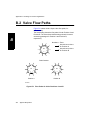
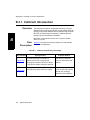
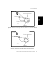
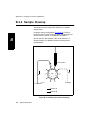
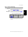
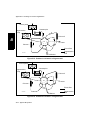
1
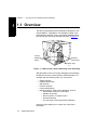
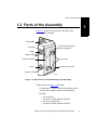
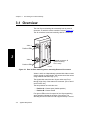
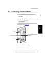
Mariner™ Dual 10-Port
Switching Valve Assembly
User Guide
© Copyright 2001, Applied Biosystems
All rights reserved.
For Research Use Only. Not for use in diagnostic procedures.
Information in this document is subject to change without notice. Applied Biosystems assumes no responsibility for any errors that
may appear in this document. This document is believed to be complete and accurate at the time of publication. In no event shall
Applied Biosystems be liable for incidental, special, multiple, or consequential damages in connection with or arising from the use
of this document.
Applied Biosystems, Delayed Extraction, SymBiot, and the fractal icon are registered trademarks of Applera Corporation or its
subsidiaries in the U.S. and certain other countries.
AB (Design), ABI, Applera, BioCAD, Biospectrometry, Data Explorer, INTEGRAL, Mariner, SPRINT, and VISION are
trademarks of Applera Corporation or its subsidiaries in the U.S. and certain other countries.
Acrobat and Adobe are registered trademarks of Adobe Systems Incorporated.
Teflon is a registered trademark of E. I. Du Pont de Nemours and Co.
Microsoft, MS, MS-DOS, Visual Basic, Windows, and Windows NT are registered trademarks of Microsoft Corporation.
RheFlex is a registered trademark and Rheodyne is a trademark of Rheodyne, L.P.
PEEK is a trademark of the Victrex Corporation.
All other trademarks are the sole property of their respective owners.
Printed in the USA, 01/2001
Part Number V900206 Rev. A
Table of Contents
Table of Contents
How to Use This Guide ..........................................................................
vii
Safety and EMC Compliance Information ..................................
ix
Chapter 1 The Dual 10-Port Switching Valve Assembly
1.1
Overview .............................................................................................. 1-2
1.2
Parts of the Assembly........................................................................... 1-3
Chapter 2 Installing the Valve Assembly
2.1
Overview .............................................................................................. 2-2
2.2
When to Install ..................................................................................... 2-2
2.3
Before You Begin.................................................................................. 2-3
2.4
2.3.1
Safety Information .................................................................. 2-3
2.3.2
Removing Original Panels ...................................................... 2-3
Installing the Valve Assembly ............................................................... 2-6
Chapter 3 Connecting the Valve Assembly
3.1
Overview .............................................................................................. 3-2
3.2
Selecting Control Mode ........................................................................ 3-3
3.3
Connecting the Valve Controls.............................................................. 3-4
3.3.1
Mariner MS Method Control ................................................... 3-4
3.3.2
External Device Control ......................................................... 3-5
Chapter 4 Preparing the Valves
4.1
Making Fluidic Connections .................................................................. 4-2
4.2
Testing the Valves ................................................................................ 4-4
Dual 10-Port Switching Valve Assembly User Guide
iii
Table of Contents
Chapter 5 Controlling the 10-Port Switching Valves
5.1
Overview .............................................................................................. 5-2
5.2
MS Method Control............................................................................... 5-2
5.3
External Device Control ........................................................................ 5-4
Chapter 6 Maintenance and Troubleshooting
6.1
Maintaining the Valves.......................................................................... 6-2
6.2
Troubleshooting the Valves................................................................... 6-3
6.3
Maintaining the Front Panel Fan ........................................................... 6-5
Appendix A Example MS Method
A.1
Example MS Method ............................................................................ A-2
A.2
Creating the Example MS Method ........................................................ A-3
A.3
Running the Example MS Method ........................................................ A-8
A.4
Displaying MS Method Status ............................................................... A-9
A.5
Stopping an MS Method ....................................................................... A-9
Appendix B Plumbing for Common Applications
B.1
Plumbing the Valves ............................................................................. B-2
B.2
Valve Flow Paths .................................................................................. B-4
B.3
Common Applications ........................................................................... B-5
B.3.1
Calibrant Introduction ............................................................. B-6
B.3.2
Sample Cleanup .................................................................... B-8
B.3.3
Column Switching .................................................................. B-9
Appendix C Warranty/Service Information
C.1
Limited Product Warranty ..................................................................... C-2
C.2
Damages, Claims, Returns ................................................................... C-5
C.3
Spare Parts .......................................................................................... C-6
Index
iv
Applied Biosystems
How to Use This Guide
1
How to Use This Guide
Purpose
of this guide
The Applied Biosystems Mariner™ Dual 10-Port Switching
Valve Assembly User Guide describes the procedures for
installing, using, maintaining and troubleshooting the dual
10-port switching valves with a Mariner™ Workstation.
Audience
This guide is intended for novice and experienced Mariner
Workstation users who utilize the optional dual 10-port
switching valve assembly.
Structure
of this guide
Chapter
The Applied Biosystems Mariner™ Dual 10-Port Switching
Valve Assembly User Guide is organized into six chapters and
three appendixes. The table below describes the material
covered in each chapter and appendix.
Content
Chapter 1, The Dual
10-Port Switching
Valve Assembly
Provides an overview of the dual 10-port switching valve
assembly and describes each of the components of the
assembly.
Chapter 2, Installing
the Valve Assembly
Provides procedures for installing the dual 10-port
switching valve assembly on a Mariner workstation.
Chapter 3,
Connecting the Valve
Assembly
Describes how to make signal connections from the valve
assembly to the Mariner workstation or to an external
device.
Chapter 4, Preparing
the Valves
Describes how to make fluidic connections and test the
valves.
Chapter 5, Controlling
the 10-Port Switching
Valves
Describes how to control the valves from Mariner MS
Method software
Chapter 6,
Maintenance and
Troubleshooting
Provides information on maintaining the valves and front
panel fan, and describes the procedure for troubleshooting
the valves.
Mariner™ Dual 10-Port Switching Valve Assembly User Guide
v
1
How to Use This Guide
Chapter
Content
Appendix A, Example
MS Method
Provides a sample MS Method for controlling the valves.
Appendix B, Plumbing
for Common
Applications
Describes how to plumb the valves and provides flow
diagrams for common LCMS applications.
Appendix C,
Warranty/Service
Information
Contains warranty, service, and return information.
Conventions
This guide uses the following conventions:
•
Bold text indicates user action. For example:
Type 0 and press Enter for the remaining fields.
•
Italic text denotes new or important words, and is also
used for emphasis. For example:
Before analyzing, always prepare fresh matrix.
Related
documentation
vi
Applied Biosystems
These related documents are shipped with your system:
•
Mariner™ Workstation User Guide – Describes
Mariner software.
•
Data Explorer™ User Guide – Describes Data
Explorer™ software.
•
Mariner™ Workstation Getting Started Guide –
Describes basic information designed to help you
quickly learn to use the Mariner workstation.
•
Spray Chamber Supplements – Describe the
procedures for installing and using optional spray
chambers.
How to Use This Guide
•
Printer documentation (depends on the printer you
purchase) – Describes how to set up and service your
printer.
•
Microsoft ® Windows NT ® User’s Guide and related
documents – Provides detailed information about the
Microsoft Windows NT user interface.
Portable document format (.PDF) versions of the Applied
Biosystems documents listed above, and this supplement, are
also available on the Mariner software installation CD.
Reference
documentation
Send us your
comments
This reference document is shipped with your system:
Varian Rotary Vane Pumps Instruction Manual –
Provides maintenance procedures for the external
mechanical pump.
Applied Biosystems welcomes your comments and
suggestions for improving its manuals. You can send your
comments in two ways:
•
Use the Technical Publications Customer Survey at:
www.appliedbiosystems.com/PerSeptive/techsup/survey.htm
•
Send e-mail to:
[email protected]
Mariner™ Dual 10-Port Switching Valve Assembly User Guide
vii
1
1
How to Use This Guide
viii
Applied Biosystems
Safety and EMC Compliance Information
1
Safety and EMC Compliance
Information
This section includes:
• Instrument safety
• Safety and EMC standards
Instrument Safety
This section includes:
•
•
•
•
•
•
Notes, Hints,
Cautions, and
Warnings
Notes, Hints, Cautions, and Warnings
Safety symbols
Before operating this instrument
Material Safety Data Sheets (MSDSs)
General Warnings
General Cautions
Notes, Hints, Cautions, and Warnings are used in this
document as follows.
A Note provides important information to the operator. For
example:
NOTE: If you are prompted to insert the boot diskette into
the drive, insert the diskette, then press any key.
A Hint provides helpful suggestions not essential to the use of
the system. For example:
Hint: To avoid complicated file naming, use Save First to
Pass or Save Best Only mode.
Mariner™ Dual 10-Port Switching Valve Assembly User Guide
ix
1
Safety and EMC Compliance Information
A Caution provides information to avoid damage to the system
or loss of data. For example:
CAUTION
Do not touch the lamp. This may damage the lamp.
A Warning provides specific information essential to the safety
of the operator. For example:
WARNING
CHEMICAL HAZARD. Familiarize yourself with the MSDSs
before using reagents or solvents.
Remarques,
recommandations
et avertissements
Une remarque fournit une information importante à
l’opérateur. Par exemple:
REMARQUE: Si on vous demande d’insérer la disquette de
démarrage dans le lecteur, insérez-la puis appuyez sur
n’importe quelle touche.
Une recommandation fournit une information destinée à éviter
des détériorations du système ou la perte de données. Par
exemple:
RECOMMANDATION
La lampe peut être endommagée. N’y touchez pas.
Un avertissement fournit une information indispensable à la
sécurité de l’operateur. Par exemple:
AVERTISSEMENT
RISQUE CHIMIQUE. Il convient de se familiariser avec la
MSDS (feuille de données concernant la sécurité des
matériaux) avant d’utiliser des réactifs ou des solvants.
x
Applied Biosystems
Safety and EMC Compliance Information
Safety symbols
The following symbols may be displayed on the system.
These symbols may also appear next to associated warnings
in this document.
Electrical symbols
The following table describes electrical symbols that may be
displayed on your instrument. Whenever such symbols appear
on instruments, observe appropriate safety procedures.
Indicates the On position of the main power switch.
Indicates the Off position of the main power switch.
Indicates the On/Off position of a push-push main power switch.
Indicates that a terminal may be connected to the signal ground
reference of another instrument. This is not a protected ground
terminal.
Indicates a protective grounding terminal that must be connected to
earth ground before any other electrical connections are made to
the instrument.
~
Indicates a terminal that can receive or deliver alternating current or
voltage.
~
Indicates a terminal that can receive or supply alternating or direct
current or voltage.
Appears next to the values of the fuses required by the system.
WARNING: Indicates the presence of high voltage and warns you to
proceed with caution.
Mariner™ Dual 10-Port Switching Valve Assembly User Guide
xi
1
1
Safety and EMC Compliance Information
Non-electrical
symbols
The following table describes non-electrical safety alert
symbols that may be displayed on your instrument.
WARNING: Alerts you to consult the manual for further information
and to proceed with caution.
WARNING: Indicates a hot surface or high temperature hazard.
Proceed with caution when working around these areas to avoid
being burned by hot components.
WARNING: Indicates that a laser is present inside the instrument,
and warns you to avoid exposure to laser light.
xii
Applied Biosystems
Safety and EMC Compliance Information
Symboles des
alertes de
sécurité
Symboles
électriques
Les symboles suivants peuvent être affichés sur le système.
Dans ce document, ces symboles peuvent aussi apparaître à
côté des avertissements auxquels ils s’associent.
Le tableau suivant donne la signification de tous les symboles
électriques qui figurent sur les appareils. En présence de l’un
de ces symboles, il est impératif de se conformer aux
consignes de sécurité appropriées.
Position MARCHE de l’interrupteur d’alimentation principal.
Position ARRÊT de l’interrupteur d’alimentation principal.
Positions MARCHE-ARRÊT de l’interrupteur d’alimentation
principal à bouton poussoir.
Borne pouvant être reliée à la mise à la terre d’un autre
appareil. Ce n’est pas une borne de mise à la terre protégée.
Borne de mise à la terre de protection devant être reliée à la
terre avant d’effectuer tout autre raccordement électrique à
l’appareil.
~
Borne recevant ou fournissant une tension ou un courant de
type alternatif.
~
Borne pouvant recevoir ou fournir une tension ou un courant
de types alternatif et continu.
Ce symbole apparaît à côté des valeurs des fusibles requis
par le système.
AVERTISSEMENT: Indique la présence d’une haute tension
et avertit l’utilisateur de procéder avec précaution.
Mariner™ Dual 10-Port Switching Valve Assembly User Guide
xiii
1
1
Safety and EMC Compliance Information
Symboles non
électriques
Le tableau suivant donne la signification des symboles
d’alertes de sécurité non électriques qui figurent sur les
appareils.
AVERTISSEMENT: Avertit l’utilisateur de la nécessité de
consulter le manuel pour obtenir davantage d’informations et
de procéder avec précaution.
AVERTISSEMENT: Danger associé à la présence d’un
appareil de chauffage. Procéder avec précaution pour éviter
de se brûler au contact de pièces ou d’éléments chauds.
AVERTISSEMENT: Indique que l’appareil renferme un laser.
Before operating
the instrument
Ensure that everyone involved with the operation of the
instrument has:
• Received instruction in general safety practices for
laboratories
• Received instruction in specific safety practices for the
instrument
• Read and understood all related MSDSs
CAUTION
Avoid using this instrument in a manner not specified by
Applied Biosystems. Although the instrument has been
designed to protect the user, this protection can be impaired
if the instrument is used improperly.
xiv
Applied Biosystems
Safety and EMC Compliance Information
Material Safety
Data Sheets
(MSDSs)
Some of the chemicals that may be used with your system are
listed as hazardous by their manufacturers. Hazards are
prominently displayed on the labels of all chemicals. In
addition, MSDSs supplied by the chemical manufacturer
provide information about:
•
•
•
•
•
•
Physical characteristics
Safety precautions
Health hazards
First-aid
Spill clean-up
Disposal procedures
Chemical manufacturers supply a current MSDS before or with
shipments of hazardous chemicals to new customers and with
the first shipment of a hazardous chemical after an MSDS
update. MSDSs provide you with the safety information you need
to store, handle, transport and dispose of the chemicals safely.
Applied Biosystems strongly recommends that you replace the
appropriate MSDS in your files each time you receive a new
MSDS packaged with a hazardous chemical.
WARNING
CHEMICAL HAZARD. Familiarize yourself with the MSDSs
before using reagents or solvents.
AVERTISSEMENT
RISQUE CHIMIQUE. Il convient de se familiariser avec la
MSDS (feuille de données concernant la sécurité des
matériaux) avant d’utiliser des réactifs ou des solvants.
Mariner™ Dual 10-Port Switching Valve Assembly User Guide
xv
1
1
Safety and EMC Compliance Information
General Warnings
WARNING
FIRE HAZARD. Using a fuse of the wrong type or rating
can cause a fire. Replace fuses with those of the same type
and rating.
AVERTISSEMENT
DANGER D’INCENDIE. L’usage d’un fusible de type ou de
valeur nominale différents risque de provoquer un incendie.
Il convient donc de remplacer les fusibles usagés par des
fusibles du même type et de la même valeur nominale.
WARNING
ELECTRICAL SHOCK HAZARD. Severe electrical shock
can result from operating the instrument without its front or
side panels in place. Do not remove instrument front or side
panels. High-voltage contacts are exposed when front or
side panels are removed.
AVERTISSEMENT
RISQUE DE DÉCHARGE ÉLECTRIQUE. Des décharges
électriques sérieuses peuvent résulter du fonctionnement
de l’appareil lorsque le panneau avant et les panneaux
latéraux sont retirés. Ne pas retirer le panneau avant ou les
panneaux latéraux. Des contacts haute tension sont
exposés lorsque les panneaux sont retirés.
xvi
Applied Biosystems
Safety and EMC Compliance Information
1
WARNING
PHYSICAL INJURY HAZARD. Always wear eye protection
when working with solvents or any pressurized liquids.
AVERTISSEMENT
Porter toujours des protections pour les yeux lorsque vous
manipulez des solvants ou tout autre liquide sous pression.
WARNING
CHEMICAL HAZARD. Before handling any chemicals, refer
to the Material Safety Data Sheet provided by the
manufacturer, and observe all relevant precautions.
AVERTISSEMENT
RISQUE CHIMIQUE. Avant de manipuler des produits
chimiques, veuillez consulter la fiche de sécurité du
matériel fournie par le fabricant, et observer les mesures de
précaution qui s’imposent.
Mariner™ Dual 10-Port Switching Valve Assembly User Guide
xvii
1
Safety and EMC Compliance Information
WARNING
PHYSICAL INJURY HAZARD. PEEK ™ tubing is a
polymeric material. Use caution when working with any
polymer tubing under pressure.
1. Always wear eye protection when close to pressurized
polymer tubing.
2. Extinguish all nearby flames if using flammable solvents.
3. Do not use PEEK tubing that has been severely stressed
or kinked.
4. Do not use PEEK tubing with tetrahydrofuran or
concentrated nitric or sulfuric acid.
5. Be aware that Methylene chloride and dimethyl sulfoxide
cause PEEK tubing to swell and greatly reduce the
rupture pressure of the tubing.
6. Be aware that high solvent flow rates (>40 ml/min), may
cause a static charge to build up on the surface of the
tubing. Electrical sparks may result.
AVERTISSEMENT
Le tubage PEEK est un matériau polymère. Prenez des
précautions lorsque vous travaillez avec un tubage
polymère sous pression.
1. Porter toujours des protections pour les yeux lorsque
vous vous trouvez à proximité d’un tubage polymère
sous pression.
2. Éteindre toutes les flammes avoisinantes si vous utilisez
des solvants inflammables.
3. Nes pas utiliser un tubage PEEK qui a déjà été
sérieusement travaillé ou plié.
xviii
Applied Biosystems
Safety and EMC Compliance Information
4. Nes pas utiliser un tubage PEEK avec du
tétrahydrofurane ou des acides nitriques et sulfuriques
concentrés.
5. Le chlorure de méthylène et le sulfoxyde de diméthyle
entraînent un gonflement du tubage PEEK et réduisent
fortement la résistance à la rupture du tubage.
6. Avec des débits d’écoulement de solvants élevés (>á
40 ml/min), une charge statique puet se développer sur
la surface du tubage. Des étincelles électriques peuvent
en résulter.
WARNING
PHYSICAL INJURY HAZARD. Use this product only as
specified in this document. Using this system in a manner
not specified may result in injury or damage to the system.
AVERTISSEMENT
Veuillez suivre avec attention les indications figurant dans
ce document lorsque vous utilisez ce produit. Un usage
différent le système causer un accident ou endommager le
système.
Mariner™ Dual 10-Port Switching Valve Assembly User Guide
xix
1
1
Safety and EMC Compliance Information
Safety and Electromagnetic Compatibility
(EMC) Standards
US Safety
standards
Canadian Safety
and EMC
standards
This instrument has been tested to and complies with
standard ANSI/UL 3101-1, “Electrical Equipment for
Laboratory Use; Part 1: General Requirements,” 1st Edition. It
is an ETL Testing Laboratories listed product.
Safety
This instrument has been tested to and complies with
standard CSA 1010, “Safety Requirements for Electrical
Equipment for Measurement, Control, and Laboratory Use;
Part 1: General Requirements.” It is an ETL Testing
Laboratories listed product.
Sécurité
Cet instrument a été vérifié avec la norme CSA 1010,
«Spécifications de sécurité du matériel électrique utilisé pour
les mesures, les contrôles et dans les laboratoires ; Partie 1 :
Spécifications générales», et il est conforme à cette norme.
C’est un produit homologué par les ETL Testing Laboratories.
EMC
This Class A digital apparatus meets all requirements of the
Canadian Interference-Causing Equipment Regulations.
Cet appareil numérique de la classe A respecte toutes les
exigences du Règlement sur le materiel brouilleur du Canada.
European safety
and EMC
standards
Safety
This instrument meets European requirements for safety
(EMC Directive 73/23/EEC). This instrument has been tested
to and complies with standard EN61010-1 “Safety
Requirements for Electrical Equipment for Measurement,
Control and Laboratory Use.”
EMC
This instrument meets European requirements for emission
and immunity (EMC Directive 98/336/EEC). This product has
been evaluated to the EN55011:1992, Group 1, Class B
“Radiated Emissions,” and EN50082-1:1992, “Generic
Immunity.”
xx
Applied Biosystems
1 The Dual 10-Port Switching
Valve Assembly
This chapter contains the following sections:
1.1
Overview ................................................ 1-2
1.2
Parts of the Assembly ............................. 1-3
Mariner™ Dual 10-Port Switching Valve Assembly User Guide
1-1
Chapter 1
The Dual 10-Port Switching Valve Assembly
1 1.1 Overview
The dual 10-port switching valve assembly is designed for use
with the Mariner™ Workstation. The assembly consists of two
pneumatically controlled, 10-port, two-position switching valves,
two column clips, and seven external connectors (Figure 1-1).
10-port
switching
valves
External
connectors
Column clips
PB100803
Figure 1-1 Mariner Dual 10-Port Switching Valve Assembly
With the addition of the dual 10-port switching valve assembly,
the Mariner becomes a more flexible LCMS workstation. For
example, with the switching valve, you can perform:
•
•
•
•
•
•
Sample injection
Calibrant introduction
Salt diversion
Fraction collection
Column backflushing
Multi-dimensional, multi-column strategies, such as:
• Solid-phase extraction to RP-HPLC
• Sample enrichment
• Direct injection of complex matrix
• Gradient stacking
• Ion exchange to reversed-phase separation
Using two valves allows you to couple any of the above
techniques.
1-2
Applied Biosystems
Parts of the Assembly
1.2 Parts of the Assembly
1
Figure 1-2 shows the components of the dual 10-port
switching valve assembly.
Gas cylinder
Control mode selection
button (recessed)
Fault LED
Valve 1
Position LEDs
Column clips
Control mode LED
Valve 2
J6 external connector
Position LEDs
PB100880
Figure 1-2 Mariner Dual 10-Port Switching Valve Assembly
These components (Figure 1-2) include:
• Two Rheodyne™ 10-port, two-position switching valves
mounted at a 45-degree angle for easier plumbing.
• Six LEDs:
•
•
•
•
One fault LED
Two Valve 1 LEDs (Position A and B)
One control mode LED
Two Valve 2 LEDs (Position A and B)
Mariner™ Dual 10-Port Switching Valve Assembly User Guide
1-3
Chapter 1
The Dual 10-Port Switching Valve Assembly
• Control-mode selection button. For information see
“Selecting Control Mode” on page 3-3.
1
• External Connectors. For information, see “Connecting
the Valve Controls” on page 3-4.
• Venting fan and removable filter (not shown).
For information, see “Maintaining the Front Panel Fan”
on page 6-5.
• Two column clips, each compatible with columns up to
24 mm in diameter and 30 cm in length.
• Internal pneumatic control.
The dual 10-port switching valve assembly requires
compressed dry gas (air or nitrogen) to operate. Gas
from the Mariner Workstation Gas 4 connector supplies
a small gas cylinder inside the valve assembly.
When you switch the valve, gas is drawn from the gas
cylinder rather than directly from the gas line. This
method stabilizes pressure and prevents fluctuation in
the curtain gas flow rate.
1-4
Applied Biosystems
2 Installing the Valve Assembly
This chapter contains the following sections:
2.1
Overview ................................................ 2-2
2.2
When to Install ........................................ 2-2
2.3
Before You Begin ....................................2-3
2.4
Installing the Valve Assembly ..................2-6
Mariner™ Dual 10-Port Switching Valve Assembly User Guide
2-1
Chapter 2
Installing the Valve Assembly
2.1 Overview
The Mariner dual 10-port switching valve assembly is usually
installed by Applied Biosystems. Use the information in this
section if you need to remove and replace the assembly
during troubleshooting.
2 2.2 When to Install
The installation procedure for the 10-port switching valve
assembly differs depending on the serial number of your
instrument and whether you purchased the valve with the
instrument or later as an accessory. The following table shows
the installation procedure for each situation.
Instrument Serial
Number
When Valve Assembly
Purchased
Valve Assembly
Installation Process
5219 or later
With instrument purchase
Factory installed
5219 or later
After instrument purchase
You install following the
directions in this document
Earlier than 5219
After instrument purchase
(upgrade)
Installed by an Applied
Biosystems Technical
Representative
2-2
Applied Biosystems
Before You Begin
2.3 Before You Begin
Before you install the valve assembly, you must:
• Read the appropriate safety information
• Remove the original panels
2.3.1 Safety Information
2
Before you install the valve assembly, read the safety
information in the front of the Mariner Workstation User
Guide.
WARNING
CHEMICAL HAZARD. All chemicals used with the
instrument, including liquid in the lines, are potentially
hazardous. Always determine what chemicals have been
used in the instrument before changing reagents or
instrument components. Wear appropriate eye protection,
clothing, and gloves when working on the instrument.
2.3.2 Removing Original Panels
Before you install the dual 10-port switching valve assembly,
you must remove the right front corner panel and inner rear
panel. If you have the optional integrated syringe pump
installed, the syringe pump is on the right front panel.
Mariner™ Dual 10-Port Switching Valve Assembly User Guide
2-3
Chapter 2
Installing the Valve Assembly
WARNING
ELECTRICAL SHOCK HAZARD. Severe electrical shock,
which could cause physical injury or death, can result from
working on an instrument when the high voltage power
supply is operating. Also, failure to power down the system
can result in damage to the instrument electronics. To avoid
electrical shock, disconnect the power supply to the
instrument, unplug the power cord, and wait at least
1 minute before working on the instrument.
After powering up, internal elements of the system can take
up to 1.5 hours to equilibrate.
2
To remove the panels:
Power down
1.
Shut down the Mariner system as described in the
Mariner Workstation User Guide , Section 8.3, “General
Maintenance.”
Remove
front panel
2.
Remove the two screws holding the Mariner front panel in
place (Figure 2-1).
PB100821
Figure 2-1 Removing the Front Panel (Optional
Integrated Syringe Pump Shown)
3.
2-4
Applied Biosystems
Gently slide the panel to the right and forward a few
inches.
Before You Begin
4.
Unplug the fan cable from the internal connector board.
If you have the optional integrated syringe pump
installed, unplug the two additional syringe pump
cables and the loop injector cable.
Remove inner
rear panel
5.
Set aside the front panel.
6.
Loosen the two screws on the left of the inner rear panel
and remove the two screws on the right. Set aside the two
removed screws (Figure 2-2).
7.
Slide the inner rear panel to the right and lift it out.
8.
Discard or store the panel. The dual 10-port switching
valve assembly replaces the panel.
Loosen
Remove
PB100805
Figure 2-2 Removing the Inner Rear Panel
Mariner™ Dual 10-Port Switching Valve Assembly User Guide
2-5
2
Chapter 2
Installing the Valve Assembly
2.4 Installing the Valve Assembly
To install the dual 10-port switching valve assembly:
Connect gas
supply line
1.
Check that gas pressure for the gas supply to the
Gas 4 connector is 80 to 100 psi (550 to 690 kPa).
WARNING
2
EXPLOSION HAZARD. Pressurized gas cylinders are
potentially explosive. Always cap the gas cylinder when
it is not in use and attach it firmly to the wall or gas
cylinder cart with approved brackets, chains, or clamps.
2.
Within the inner rear panel opening, locate the gas supply
line (white Teflon® tubing labeled G4). Gently pull the
unattached end of the gas supply line through the rear
panel opening.
3.
Connect the gas supply line to the fitting on the back of
the dual 10-port switching valve assembly (Figure 2-3).
Gently insert the tubing into the fitting until firmly seated.
NOTE: When the tubing is firmly seated, you can pull
on it without dislodging it from the fitting.
Fitting
Gas
supply line
PB100808
Figure 2-3 Connecting the Gas Supply Line
2-6
Applied Biosystems
Installing the Valve Assembly
Position valve
panel
Connect power
cable
4.
Position the rear panel of the dual 10-port switching valve
assembly in the rear panel opening. Check that the gas
supply line is unobstructed.
5.
Slide the assembly to the left and into place, aligning the
left screw holes under the left screws.
6.
Reinstall the two right screws and tighten the two left
screws.
7.
Draw the ribbon power cable across the front of the
pressurized gas cylinder. A red line on the cable
indicates its top edge.
2
Connect the cable to J10 on the internal connector
board (Figure 2-4). Pin 1 is at the top of the connector.
NOTE: Avoid twisting the cable. Keeping the cable flat
ensures the correct pin alignment is maintained.
Internal
connector
board
Pin 1 (at the top of
the connector)
Red line
indicating
cable Pin 1
J10
switching
valve power
PB100809
Figure 2-4 Connecting the Switching Valve Power Cable
Mariner™ Dual 10-Port Switching Valve Assembly User Guide
2-7
Chapter 2
Installing the Valve Assembly
Replace front
panel
8.
Position the front panel at the front of the opening.
9.
Connect the fan power cable from the front panel to the
J6 connector (Figure 2-5) on the internal connector
board.
If you have the optional integrated syringe pump on the
front panel, connect the three additional cables.
The table below summarizes the connections.
2
Cable
Connector
Fan
J6
Syringe pump power (Optional)
J7
Syringe pump signal (Optional)
Syr
Syringe pump loop injector (Optional)
J5
Syr
J5
J6
J7
Slots for
panel tabs
PB100807
Figure 2-5 Dual 10-Port Switching Valve
Assembly Internal Connectors
2-8
Applied Biosystems
Installing the Valve Assembly
10. Fit the front panel in place by inserting the tabs on the
front panel of the integrated syringe into the slots on the
frame of the workstation (Figure 2-5 on page 2-8).
11. Secure the front panel with the two screws on the right
side of the workstation (Figure 2-1 on page 2-4).
Powering up
Start up the Mariner system as described in the Mariner
Workstation User Guide, Section 2.7, Startup and Shutdown.
2
Mariner™ Dual 10-Port Switching Valve Assembly User Guide
2-9
Chapter 2
Installing the Valve Assembly
2
2-10 Applied Biosystems
3 Connecting the Valve
Assembly
This chapter contains the following sections:
3.1
Overview ................................................ 3-2
3.2
Selecting Control Mode........................... 3-3
3.3
Connecting the Valve Controls ................3-4
Mariner™ Dual 10-Port Switching Valve Assembly User Guide
3-1
Chapter 3
Connecting the Valve Assembly
3.1 Overview
The dual 10-port switching valve assembly has an external
connector, J6, which is used to control the valves (Figure 3-1).
The J6 connector is mounted vertically, with Pin 1 at the top.
Valve 1
Position LEDs
3
Valve 2
External connector J6
(Valve Controls),
Pin 1 at top
Position LEDs
PB100881
Figure 3-1 Dual 10-Port Switching Valve Assembly External Connectors
Valves 1 and 2 are independently operated with either contact
closure signals or pulse signals. You cannot control the valves
using transistor-transistor logic (TTL).
The signals that control the two 10-port valves use Pins 1
through 4 (top four) of the external J6 connector. (Pins 5 and 6
are for future use.)
The two positions for each valve are:
• Position A—Contact open (default position)
• Position B—Contact closed
Four green LEDs on the front panel of the 10-port switching
valve assembly indicate the position of the valves. The
switching time from Position A to B is approximately 1 second.
3-2
Applied Biosystems
Selecting Control Mode
3.2 Selecting Control Mode
The 10-Port switching valves can operate in two modes:
• Contact mode
• Pulse mode
The control mode LED, located on the valve panel between
Valve 1 and Valve 2 (Figure 3-2), indicates the current control
mode of the 10-Port Switching Valves.
• On–Contact Mode
• Off–Pulse Mode
To switch between the two control modes, push the control
mode selection button (Figure 3-2).
3
Valve 1
Control mode selection button
(recessed)
Control mode LED
Valve 2
PB100881
Figure 3-2 Selecting Control Mode
Mariner™ Dual 10-Port Switching Valve Assembly User Guide
3-3
Chapter 3
Connecting the Valve Assembly
3.3 Connecting the Valve Controls
You can control the valves using the Mariner MS Method
feature or an external device.
3.3.1 Mariner MS Method Control
The MS Method feature in the Mariner Instrument Control
Panel allows you to trigger valve actions, based on time or
conditions, using the Mariner contact outputs. See
Appendix A, Example MS Method.
To connect the Mariner MS Method contacts:
1.
3
Connect the Mariner Workstation 8-pin output
connector on the rear of the right side panel to the J6
external connector on the valve assembly (Figure 3-3).
8-pin
output
connector
J6 external connector
PB100803
Figure 3-3 Dual 10-Port Switching Valve Assembly and Mariner Connectors
3-4
Applied Biosystems
Connecting the Valve Controls
2.
Connect the pins on the Mariner 8-pin connector to the J6
external connector pins as specified in the following table.
Valve Number and
Position
8-pin
Connector
J6
Connector
Corresponding
MS Method Setting
Valve 1, Position A
Pin 1
Pin1
Contact out #1 open
Valve 1, Position B
Pin 2
Pin 2
Contact out #1 close
Valve 2, Position A
Pin 3
Pin 3
Contact out #2 open
Valve 2, Position B
Pin 4
Pin 4
Contact out #2 close
3.3.2 External Device Control
To control the valves using an external device such as an LC
system, connect your external device to the J6 connector.
Pins 1 and 2 control Valve 1, and Pins 3 and 4 control Valve 2.
The following table indicates the valve control assignments.
Valve Number and
Position
J6 Connector
Contact Signal
Valve 1, Position A
Pin 1 and Pin 2
Contact open
Valve 1, Position B
Pin 1 and Pin 2
Contact close
Valve 2, Position A
Pin 3 and Pin 4
Contact open
Valve 2, Position B
Pin 3 and Pin 4
Contact close
Refer to the user manual provided with your external device
for contact closure signal information. If necessary, prime the
device and make the injection as described in the user manual
provided with the external device.
Mariner™ Dual 10-Port Switching Valve Assembly User Guide
3-5
3
Chapter 3
Connecting the Valve Assembly
3
3-6
Applied Biosystems
4 Preparing the Valves
This chapter contains the following sections:
4.1
Making Fluidic Connections ....................4-2
4.2
Testing the Valves ................................... 4-4
Mariner™ Dual 10-Port Switching Valve Assembly User Guide
4-1
Chapter 4
Preparing the Valves
4.1 Making Fluidic Connections
Plumbing
diagrams
Connecting
tubing
Appendix B, Plumbing for Common Applications, provides
sample plumbing diagrams for the dual 10-port switching valve
assembly. For additional information on possible
configurations, refer to the Solutions Book, available on
Rheodyne’s web site (www.rheodyne.com).
Use Rheodyne™ RheFlex® fittings to connect tubing to the
10-port switching valves.
WARNING
CHEMICAL HAZARD. If you run 100% IPA, 100%
acetonitrile, or 100% THF at pressures above 1,500 psi
(10,340 kPa), do not use PEEK ™ tubing.
Using these solvents at pressures above 1,500 psi may
cause the PEEK tubing to burst.
To connect Rheodyne RheFlex fittings to tubing:
4
1.
Slip a compression fitting over the end of the tubing.
2.
Slip a split ferrule over the end of the tubing, with the
tapered end of the ferrule pointing away from the
compression fitting and into the valve (Figure 4-1) .
Make sure at least 1/16-inch of tubing extends beyond the
ferrule.
If necessary,
remove knurled ring
to tighten fitting
with a wrench.
PB100018
Figure 4-1 Connecting Rheodyne Fittings to Tubing
4-2
Applied Biosystems
Making Fluidic Connections
3.
Bottom the tubing in a port, then finger-tighten the
compression fitting.
4.
For high-pressure operation (3,000 to 5,000 psi [20,680 to
34,470 KPa]), tighten fittings 1/4-turn with a wrench. You
can remove the knurled ring for easier access to the
fitting.
WARNING
PHYSICAL INJURY HAZARD. Wear appropriate protective
eyewear, clothing, and gloves when inspecting and
adjusting fittings.
4
Mariner™ Dual 10-Port Switching Valve Assembly User Guide
4-3
Chapter 4
Preparing the Valves
4.2 Testing the Valves
After plumbing the system, check for leaks and excessive
backpressure. The valves are rated for a maximum pressure
of 5,000 psi (34,470 kPa; 344 bar).
Checking for
leaks
Start solvent flow at a low rate and observe all fittings for
leaks. If no leaks are observed, slowly increase the flow rate to
your application flow rate.
If you observe leaks, adjust or replace the tubing and tighten
the fittings.
Checking
backpressure
4
4-4
Applied Biosystems
If you are using an LC system, check the backpressure of the
LC system after starting solvent flow. Bypass the LC column
and UV detector, if applicable. Check that the system pressure
does not exceed the rating of any component in the system.
5 Controlling the 10-Port
Switching Valves
This chapter contains the following sections:
5.1
Overview ................................................ 5-2
5.2
MS Method Control ................................. 5-2
5.3
External Device Control .......................... 5-4
Mariner™ Dual 10-Port Switching Valve Assembly User Guide
5-1
Chapter 5
Controlling the 10-Port Switching Valves
5.1 Overview
You can control the 10-port switching valves in two ways:
• Mariner MS Method software
• External device
5.2 MS Method Control
To control the 10-port switching valves using Mariner software:
1.
Create an MS Method in the Mariner software
Instrument Control Panel by selecting New MS Method
from the Method menu. The MS Method Editor is
displayed (Figure 5-1).
Set contact out for
selected segment
5
Set contact out for
selected event
Figure 5-1 MS Method Editor Dialog Box
5-2
Applied Biosystems
MS Method Control
NOTE: See the Mariner Workstation User Guide,
Chapter 7, Using MS Method, for information on creating an
MS Method. An example MS Method is provided in
Appendix A, Example MS Method, of this document.
2.
Set the Contact Out for the Segment Setting and Event
Setting as appropriate. Refer to the following table for
contact out settings.
Valve Position
MS Method
Contact Out Settings
Valve 1, Position A
Contact out #1 open
Valve 1, Position B
Contact out #1 close
Valve 2, Position A
Contact out #2 open
Valve 2, Position B
Contact out #2 close
5
Mariner™ Dual 10-Port Switching Valve Assembly User Guide
5-3
Chapter 5
Controlling the 10-Port Switching Valves
5.3 External Device Control
Connect the device as described in “External Device Control”
on page 3-5 of this document. Refer to the user manual
provided with the external device for information on contact
closure triggers.
5
5-4
Applied Biosystems
6 Maintenance and
Troubleshooting
This chapter contains the following sections:
6.1
Maintaining the Valves ............................ 6-2
6.2
Troubleshooting the Valves .....................6-3
6.3
Maintaining the Front Panel Fan .............6-5
Mariner™ Dual 10-Port Switching Valve Assembly User Guide
6-1
Chapter 6
Maintenance and Troubleshooting
6 6.1 Maintaining the Valves
Each valve has an internal rotor seal that provides a highpressure seal against the face of the valve (stator). The rotor
seal wears with use and needs periodic replacing.
To maintain optimum operation of the 10-port switching valves,
contact an Applied Biosystems Technical Representative to
change the rotor seal. To reach Applied Biosystems Technical
Support, refer to the information on the back cover of this
manual.
6-2
Applied Biosystems
Troubleshooting the Valves
6.2 Troubleshooting the Valves
Fault LED
6
A yellow Fault LED is located on the valve panel, to the right of
Valve 1 (Figure 6-1). If this LED is illuminated, one of the
valves failed to switch properly.
Fault LED
PB100882
Figure 6-1 Fault LED for Valves 1 and 2
Error messages
In addition, the Mariner control software monitors the state of
the dual 10-port switching valves. If the switching valves do
not function properly, acquisition is halted and an error
message appears (Figure 6-2).
Figure 6-2 Switching Valve Fault Error Message
Mariner™ Dual 10-Port Switching Valve Assembly User Guide
6-3
Chapter 6
Maintenance and Troubleshooting
Clearing faults
6
If the yellow Fault LED is illuminated, or you receive a
switching valve fault error message:
1.
Check that all connections to the valve assembly are
secure.
2.
Check that the gas flow is at the appropriate pressure.
3.
Switch the valve state with a contact closure signal from
either the Mariner MS Method software or the external
device. For more information, see Chapter 5, Controlling
the 10-Port Switching Valves.
4.
Click OK to clear the error message and continue
acquisition.
If you are unable to resolve the problem, call Applied
Biosystems Technical Support.
6-4
Applied Biosystems
Maintaining the Front Panel Fan
6.3 Maintaining the Front Panel Fan
The front panel fan (Figure 6-3) contains a replaceable filter.
Fan
PB100803
Figure 6-3 Front Panel Fan
WARNING
CHEMICAL WASTE HAZARD. Wear appropriate eyewear,
clothing, and gloves when handling a dirty filter. Dispose of
the dirty filter in accordance with all applicable local, state,
and federal health and environmental regulations.
Mariner™ Dual 10-Port Switching Valve Assembly User Guide
6-5
6
Chapter 6
Maintenance and Troubleshooting
To replace the fan filter:
6
1.
Remove the dirty filter by pulling the release bar
(Figure 6-4). The dirty filter drops down.
2.
Slide a new filter (part number V106165) in and up until it
locks in place.
Release bar
PB100810
Figure 6-4 Replacing the Fan Filter
6-6
Applied Biosystems
A Example MS Method
This appendix contains the following sections:
A.1
Example MS Method .............................. A-2
A.2
Creating the Example MS Method.......... A-3
A.3
Running the Example MS Method .......... A-8
A.4
Displaying MS Method Status ................ A-9
A.5
Stopping an MS Method ......................... A-9
Mariner™ Dual 10-Port Switching Valve Assembly User Guide
A-1
Appendix A
Example MS Method
A A.1 Example MS Method
Before you begin
Read the Mariner Workstation User Guide, Chapter 7, Using
MS Method, before proceeding.
Overview
The example MS Method is designed to cycle through all the
valve positions. The stages of the cycle are:
At the start of the segment:
•
•
Valve 1 is set to Position A
Valve 2 is set to Position A
In Event 1:
•
•
Valve 1 is switched to Position B
Valve 2 remains in Position A
In Event 2:
•
•
Valve 1 is switched to Position A
Valve 2 is switched to Position B
At the end of the segment:
•
•
Valve 1 remains in Position A
Valve 2 is switched to Position A
The following table summarizes the position of the valves at
the completion of each stage.
Cycle Stage
Valve 1 Position
Valve 2 Position
Start
A
A
Event #1
B
A
Event #2
A
B
End
A
A
This MS Method repeats the cycle for 10 minutes.
A-2
Applied Biosystems
Creating the Example MS Method
A.2 Creating the Example
MS Method
A
To create the example MS Method:
1. From the Method menu in the Instrument Control Panel,
select New MS Method.
The MS Method Editor is displayed (Figure A-1).
2.
Set Method, Segment, and Event Setting parameters as
described in the following sections.
Method
setting
Segment
setting
Event bar
Event
setting
actions
Branching
Figure A-1 MS Method Editor Dialog Box
Method setting
To specify the Method Setting (Figure A-1):
1.
Select Reset All Contact Out at End to set contacts to
the initial state of Open at the end of the MS Method.
2.
Set the Total Number of Segments to 1.
Mariner™ Dual 10-Port Switching Valve Assembly User Guide
A-3
Appendix A
A
Example MS Method
Segment setting
To specify the segment setting:
1.
In the Duration field, enter 00:10:00 to run the segment
for 10 minutes.
2.
Select the Contact Out check box, then click Set. The
ContactOut settings for Segment #1 dialog box appears
(Figure A-2).
3.
In the ContactOut settings for Segment #1 dialog box,
select the options shown in Figure A-2.
Figure A-2 ContactOut Segment Settings Dialog Box
A-4
Applied Biosystems
4.
Click OK. Valve 1 and Valve 2 are set to Position A.
5.
If you want to create two events for the segment,
select 2 in the Event Count selection box.
Creating the Example MS Method
Event #1 actions
1.
Select Event #1 in the event bar (Figure A-1 on
page A-3).
2.
Select the Instrument Setting check box, then click
Import BIC File.
3.
Select an appropriate .BIC file.
4.
Select the Data Acquisition check box to enable data
acquisition, or deselect to disable data acquisition.
A
NOTE: When Data Acquisition is disabled, the event
executes when reached, but no data point is acquired
during the event. The data file does not include a data point
for this event period.
5.
Select the Contact Out check box, then click Set. The
ContactOut Settings for Event #1 dialog box appears
(Figure A-3).
6.
In the ContactOut Settings for Event #1 dialog box, select
the options shown in Figure A-3.
Figure A-3 ContactOut Settings for Event #1 Dialog Box
7.
Click OK. Valve 1 is set to Position B and Valve 2 is set
to Position A.
8.
Select Repeat to trigger the contact every time Event #1
occurs.
Mariner™ Dual 10-Port Switching Valve Assembly User Guide
A-5
Appendix A
Example MS Method
Branching for
Event #1
A
Event #2 actions
To send the MS Method to Event #2 at the end of Event #1:
1.
Select Always Go To.
2.
In the Segment # drop-down list, select 1.
3.
In the Event # drop-down list, select 2.
To specify Event #2 actions:
1.
Select Event #2 in the event bar.
2.
Select the Instrument Setting check box, then click
Import BIC File.
3.
Select an appropriate .BIC file.
4.
Select the Data Acquisition check box to enable data
acquisition, or deselect to disable data acquisition.
NOTE: When Data Acquisition is disabled, the event
executes when called, but no spectrum is acquired during
the event. The data file does not include a data point for this
event period.
5.
Select the Contact Out check box, then click Set. The
ContactOut Settings for Event #2 dialog box appears
(Figure A-4).
6.
In the ContactOut settings for Event #2 dialog box, select
the options shown in Figure A-4.
Figure A-4 ContactOut Settings for Event #2 Dialog Box
A-6
Applied Biosystems
Creating the Example MS Method
Branching for
Event #2
Saving the
MS Method
7.
Click OK. Valve 1 is set to Position A and Valve 2 is set
to Position B.
8.
Select Repeat to trigger the contact every time Event #2
occurs.
To send the MS Method to Event #1 at the end of Event #2:
1.
Select Always Go To.
2.
In the Segment # drop-down list, select 1.
3.
In the Event # drop-down list, Select 1.
To save the MS Method for future use:
1.
Click Save, then name the MS Method
“msmethod for contact switching.”
2.
Click Close.
Mariner™ Dual 10-Port Switching Valve Assembly User Guide
A-7
A
Appendix A
Example MS Method
A A.3 Running the Example
MS Method
Before running the MS Method, read the Mariner Workstation
User Guide, Section 7.4, Running an MS Method. Check the
following parameters in the Mariner Instrument Control Panel:
1.
Verify Instrument State set to On
2.
From the View menu on the Instrument Control Panel,
select Data Storage, then enter or select:
•
•
•
•
•
•
Root Directory
Directory
File Name
Standby at End of Acquisition
Start On conditions, including Start Delay time
Comment information
For information, see the Mariner Workstation User Guide,
Section 4.8.8, Data Storage.
NOTE: Stop On conditions and Repeat Acquisition are
ignored when you run an MS Method. Acquisition
duration is determined by MS Method Total Run Time.
3.
4.
From the Method menu, select one of the following:
•
Run—Starts the MS Method without acquiring data.
This option is useful to test the timing and event
actions in an MS Method before acquiring data.
•
Run and Acquire—Starts the MS Method and
acquires data.
In the displayed dialog box, select msmethod for contact
switching.msm, then click Open.
The method runs. Data is acquired if you selected the Run
and Acquire command.
A-8
Applied Biosystems
Displaying MS Method Status
A.4 Displaying MS Method Status
A
To display MS Method status, select Acquisition Status from
the View menu. MS Method Status is displayed at the bottom
of the Acquisition status page (Figure A-5).The name of the
data file acquired by the MS Method is displayed in the
Acquisition Status section of the page.
Figure A-5 MS Method Status
A.5 Stopping an MS Method
To stop an MS Method, select Stop from the Method menu.
Mariner™ Dual 10-Port Switching Valve Assembly User Guide
A-9
Appendix A
Example MS Method
A
A-10 Applied Biosystems
B Plumbing for Common
Applications
This appendix contains the following sections:
B.1
Plumbing the Valves .............................. B-2
B.2
Valve Flow Paths ................................... B-4
B.3
Common Applications ............................ B-5
B.3.1
Calibrant Introduction................. B-6
B.3.2
Sample Cleanup ........................ B-8
B.3.3
Column Switching ...................... B-9
Mariner™ Dual 10-Port Switching Valve Assembly User Guide
B-1
Appendix B Plumbing for Common Applications
B.1 Plumbing the Valves
B
Overview
Plumb the 10-port switching valves with 1/16-inch ID tubing.
Plumb for Position A and/or B as appropriate. The switching
time from Position A to Position B is approximately 1 second.
Before you
begin
Before you begin, read Chapter 4, Preparing the Valves, and
Chapter 5, Controlling the 10-Port Switching Valves. In
addition, read the safety information in Safety and EMC
Compliance Information on page ix.
WARNING
CHEMICAL HAZARD. Some of the chemicals used with
Applied Biosystems instruments are potentially hazardous
and can cause injury, illness or death. Always determine
what chemicals have been used in the instrument before
changing reagents or instrument components.
Read and understand the Material Safety Data Sheets
(MSDSs) provided by the chemical manufacturer before
you store, handle, or work with any chemicals or hazardous
materials.
Minimize contact with and inhalation of chemicals. Wear
appropriate personal protective equipment when handling
chemicals (e.g., safety glasses, gloves, or clothing).
Consult the listing in the MSDS.
Do not leave chemical containers open.
Check regularly for chemical leaks or spills. If a leak or spill
occurs, follow the manufacturer’s clean-up procedures as
recommended on the MSDS.
Comply with all applicable laws and regulations related to
chemical storage, handling, and disposal.
B-2
Applied Biosystems
Plumbing the Valves
WARNING
CHEMICAL WASTE HAZARD. Wastes produced by
Applied Biosystems instruments are potentially hazardous
and can cause injury, illness, or death.
Read and understand the material safety data sheets
(MSDSs) provided by the manufacturers of the chemicals in
the waste container before you store, handle, or dispose of
chemical waste.
Handle chemical wastes in a fume hood.
Minimize contact with and inhalation of chemical waste.
Wear appropriate personal protective equipment when
handling chemicals (e.g., safety glasses, gloves, or
clothing). Always mix and prepare hazardous materials
beneath an operating fume hood.
Seal the waste container with the cap provided after
disposing of the contents.
Dispose of the contents of the waste container in
accordance with good laboratory practices and local,
state/provincial, or national environmental and health
regulations.
Information on sample handling is provided in the Mariner
Workstation User Guide, Section 3.5, Sample, Solvent, and
LC Column Guidelines. For additional plumbing information,
see the Rheodyne Solutions Book, available on the Rheodyne
web site (www.rheodyne.com).
Mariner™ Dual 10-Port Switching Valve Assembly User Guide
B-3
B
Appendix B Plumbing for Common Applications
B.2 Valve Flow Paths
Figure B-1 shows all the 10-port valve flow paths, for
reference only.
The first drawing shows the flow paths for both Position A and
Position B. The second and third drawings show the internal
connecting passages for Position A and Position B,
respectively.
B
2
1
10
3
4
V1
9
5
8
6
Numbers = Ports
Internal connections
=
for Position A
Internal connections
=
for Position B
7
Both Positions
2
1
4
2
10
3
V1
9
5
8
6
7
Position A
1
10
3
4
V1
9
5
8
6
7
Position B
PB100811
Figure B-1 Flow Paths for Valve Positions A and B
B-4
Applied Biosystems
Common Applications
B.3 Common Applications
Overview
This section includes plumbing diagrams for:
•
•
•
Section B.3.1, Calibrant Introduction
Section B.3.2, Sample Cleanup
Section B.3.3, Column Switching
Plumb the 10-port switching valves with 1/16-inch ID tubing.
Plumb for Position A and/or B as appropriate. The switching
time from Position A to Position B is approximately 1 second.
Mariner™ Dual 10-Port Switching Valve Assembly User Guide
B-5
B
Appendix B Plumbing for Common Applications
B.3.1 Calibrant Introduction
Overview
The calibrant introduction configuration allows you to inject
calibrant before running your sample. In this configuration, the
syringe pump pushes calibrant into the sample loop, and then
flow from an external device pushes the calibrant from the
sample loop into the Mariner workstation.
Examples of external devices are an LC system, another
valve, or a pump.
B
Flow
Description
Table B-1 describes the delivery sequence for the calibrant
introduction configuration.
Table B-1 Calibrant Introduction Flow Paths
Valve Position
A
(Figure B-2)
B
(Figure B-3)
B-6
Syringe Pump
External Source
A continuous flow of calibrant is
delivered from the syringe pump
through the sample loop and to waste.
This fills the sample loop with calibrant.
Flow from the external
device is delivered to the
Mariner.
Syringe pump is offline (Flow from the
syringe pump goes directly to waste).
Flow from the external
device is delivered into the
sample loop, pushing
calibrant into the Mariner.
Applied Biosystems
Common Applications
Syringe pump
Flow from external device
Sample loop
2
1
10
3
4
To waste
V1
B
9
5
8
6
7
PB100815A
To Mariner
Figure B-2 Position A: Delivering Calibrant to Sample Loop and Flow to Mariner
Syringe pump
is now offline
Flow from external device
Sample loop
filled with calibrant
2
1
10
3
4
V1
9
5
8
6
7
PB100815B
To Mariner
Figure B-3 Position B: Delivering Calibrant and Flow to Mariner
Mariner™ Dual 10-Port Switching Valve Assembly User Guide
B-7
Appendix B Plumbing for Common Applications
B.3.2 Sample Cleanup
The sample cleanup configuration allows you to desalt a
sample online.
In sample cleanup configuration (Figure B-4), Position A
diverts the flow from the column to waste. Position B directs
the flow from the column to the Mariner Workstation.
See the Mariner Workstation User Guide , Section 3.6,
Sample Cleanup, for additional cleanup techniques and
considerations.
B
From column
2
1
10
3
4
V1
9
5
8
6
7
PB100813
To waste
To Mariner
Position A
Position B
Figure B-4 Plumbing for Online Desalting
B-8
Applied Biosystems
Common Applications
B.3.3 Column Switching
Overview
Flow
Description
Using the column switching configuration allows you to work
with one LC column while the second LC column is being
regenerated (Figure B-5 and Figure B-6).
When you use the column switching configuration, one column
elutes sample as the other column regenerates. Table B-2
summarizes the eluting and regenerating cycle.
Table B-2 Column Switching Flow Paths
Valve Position
Column 1
Column 2
A (Figure B-5)
Elutes to the Mariner
Regenerates
B (Figure B-6)
Regenerates
Elutes to the Mariner
The columns regenerate with gradient buffer at the starting
composition.
Mariner™ Dual 10-Port Switching Valve Assembly User Guide
B-9
B
Appendix B Plumbing for Common Applications
Eluent pump
Autosampler
Regeneration
pump
Column 2
2
B
1
3
10
V1
4
9
5
To waste
8
6
Column 1
7
Eluent flow
Regeneration
flow
PB100814A
To Mariner
Figure B-5 Position A: Column 2 is Regenerated
Eluent pump
Autosampler
Regeneration
pump
Column 2
2
1
3
4
10
V1
9
5
Column 1
To waste
8
6
7
Eluent flow
PB100814B
To Mariner
Figure B-6 Position B: Column 1 is Regenerated
B-10 Applied Biosystems
Regeneration
flow
C Warranty/Service Information
This appendix contains the following sections:
C.1
Limited Product Warranty....................... C-2
C.2
Damages, Claims, Returns .................... C-5
C.3
Spare Parts............................................ C-6
Applied Biosystems supplies or recommends certain configurations of computer
hardware, software, and peripherals for use with its instrumentation. Applied
Biosystems reserves the right to decline support for or impose charges for
supporting nonstandard computer configurations or components that have not
been supplied or recommended by Applied Biosystems. Applied Biosystems
also reserves the right to require that computer hardware and software be
restored to the standard configuration prior to providing service or technical
support. For systems such as Mariner ™, VISION™, BioCAD™, SPRINT™, or
INTEGRAL™, which have built-in computers, installing unauthorized hardware
or software may void the Warranty or Service Plan.
Mariner™ Dual 10-Port Switching Valve Assembly User Guide
C-1
Appendix C
Warranty/Service Information
C.1 Limited Product Warranty
Limited warranty
Applied Biosystems warrants that all standard components of
the Mariner™ Dual 10-Port Switching Valve Assembly will be
free of defects in materials and workmanship for a period of
ninety (90) days. Applied Biosystems will repair or replace, at
its discretion, all defective components during this warranty
period. After this warranty period, repairs and replacement
components may be purchased from Applied Biosystems at its
published rates. Applied Biosystems also provides service
agreements for post-warranty coverage. Applied Biosystems
reserves the right to use new, repaired, or refurbished
instruments or components for warranty and post-warranty
service agreement replacements. Repair or replacement of
products or components under warranty does not extend the
original warranty period.
Applied Biosystems warrants that all optional accessories
supplied with its Mariner™ Workstations, such as peripherals,
printers, and special monitors, will be free of defects in
materials and workmanship for a period of ninety (90) days.
Applied Biosystems will repair or replace, at its discretion,
defective accessories during this warranty period. After this
warranty period, Applied Biosystems will pass on to the buyer,
to the extent that it is permitted to do so, the warranty of the
original manufacturer for such accessories.
C
With the exception of consumable and maintenance items,
replaceable products or components used on the instrument
are themselves warranted to be free of defects in materials
and workmanship for ninety (90) days.
Applied Biosystems warrants that chemicals and other
consumable products will be free of defects in materials and
workmanship when received by the buyer, but not thereafter,
unless otherwise specified in documentation accompanying
the product.
C-2
Applied Biosystems
Limited Product Warranty
Applied Biosystems warrants that for a period of ninety (90)
days from the date of installation, the software designated for
use with the product will perform substantially in accordance
with the function and features described in its accompanying
documentation when properly installed on the product. Applied
Biosystems does not warrant that the operation of the
instrument or software will be uninterrupted or error free.
Applied Biosystems will provide any software corrections or
“bug-fixes” if and when they become available, for a period of
ninety (90) days after installation.
Warranty period
effective date
Any applicable warranty period under these sections will begin
on the date of installation for hardware and software installed
by Applied Biosystems personnel, unless that date has been
delayed at the buyer's request. In that case, and for all
hardware and software installed by the buyer, and for all other
products, the applicable warranty period begins the date the
component is received by the buyer.
Warranty
exceptions
The above warranties shall not apply to defects resulting from
misuse, neglect, or accident, including without limitation:
operation with incompatible solvents or samples in the system;
operation outside of the environmental or use specification
instructions for the product or accessories; performance of
improper or inadequate maintenance by the user; installation
of software or interfacing not supplied by Applied Biosystems;
and modification or repair of the product or the software not
authorized by Applied Biosystems.
The foregoing provisions set forth Applied Biosystems’ sole
and exclusive representations, warranties, and obligations
with respect to its products, and Applied Biosystems makes no
other warranty of any kind whatsoever, expressed or implied,
including without limitation, warranties of merchantability and
fitness for a particular purpose, whether arising from a statute
or otherwise in law or from a course of dealing or usage of
trade, all of which are expressly disclaimed. Such limited
warranty is given only to buyer or any third party in the event
of use of products furnished hereunder by any third party.
Mariner™ Dual 10-Port Switching Valve Assembly User Guide
C-3
C
Appendix C
Warranty/Service Information
Warranty
limitations
The remedies provided herein are the buyer's sole and
exclusive remedies. Without limiting the generality of the
foregoing, in no event shall Applied Biosystems be liable,
whether in contract, in tort, warranty, or under any statute
(including without limitation, any trade practice, unfair
competition, or other statute of similar import) or on any other
basis, for direct, indirect, punitive, incidental, multiple,
consequential, or special damages sustained by the buyer or
any other person, whether or not foreseeable and whether or
not Applied Biosystems is advised of the possibility of such
damage, including without limitation, damage arising from or
related to loss of use, loss of data, failure or interruption in the
operation of any equipment or software, delay in repair or
replacement, or for loss of revenue or profits, loss of good will,
loss of business or other financial loss or personal injury or
property damage.
No agent, employee, or representative of Applied Biosystems
has any authority to bind Applied Biosystems to any
affirmation, representation, or warranty concerning the product
that is not contained in this Limited Warranty Statement. Any
such affirmation, representation, or warranty made by any
agent, employee, or representative of Applied Biosystems will
not be binding on Applied Biosystems.
C
This warranty is limited to the buyer of the product from
Applied Biosystems and is not transferable.
C-4
Applied Biosystems
Damages, Claims, Returns
C.2 Damages, Claims, Returns
Damages
Unpack shipments promptly after receipt to check for any
concealed damage.
If you discover damage, stop unpacking. Contact the shipping
carrier and request inspection by a local agent. Secure a
written report of the findings to support any claim. Do not
return damaged goods to Applied Biosystems without first
securing an inspection report and contacting Applied
Biosystems Technical Support for a Return Authorization (RA)
number.
Claims
Returns
After a damage inspection report is secured, Applied
Biosystems will supply the replacements and process claims
that are initiated by either party.
Do not return any material without prior notification and
authorization.
If for any reason it becomes necessary to return material to
Applied Biosystems, contact Applied Biosystems Technical
Support or your nearest Applied Biosystems subsidiary or
distributor for:
•
•
•
•
Return Authorization (RA) number
Forwarding address
Decontamination instructions
Packing and shipping instructions
Place the RA number in a prominent location on the outside of
the shipping container, and return the material to the address
designated by the Applied Biosystems representative.
Mariner™ Dual 10-Port Switching Valve Assembly User Guide
C-5
C
Appendix C
Warranty/Service Information
C.3 Spare Parts
The following spare parts are available from Applied
Biosystems:
Description
C
C-6
Applied Biosystems
Part Number
Bottle Assembly
V700831
Fan Filter (2.36 in.)
V106165
PC Board
V750092
Rheodyne Valve Assembly
V700829
Solenoid Valve Bank
4318193
Index
A
Applied Biosystems, technical
support 6-2, C-1
B
Backpressure, checking 4-4
Buffer hazards 2-3
C
Calibrant introduction B-6
Checking
backpressure 4-4
for leaks 4-4
Column switching B-9
Common applications
calibrant introduction B-6
column switching B-9
plumbing B-2
sample cleanup B-8
Computer
configuration requirement C-1
technical support for altered
configuration C-1
Connecting
for external device control 3-5
gas supply line 2-6
modem 2-1
power cable 2-7
tubing 4-2
valve controls 3-4
Contact closure
control mode 3-3
control mode LED 3-3
programming MS Method for A-5, A-6
Control mode
contact mode 3-3
LED 3-2, 3-3
pulse mode 3-3
selecting 3-3
selection button 3-2, 3-3
Controlling valves
description 5-2
external device 5-4
MS Method 5-2
Conventions, Notes, Hints, Cautions,
and Warnings ix
Creating, example MS Method A-3
D
Damage, reporting C-5
E
Electromagnetic compliance xx
EMC standards xx
Example MS Method A-1
External device, controlling the
valves 5-4
F
Fittings, preventing leaks at high
pressure 4-3
Flow paths, valve positions A and B B-4
Front panel
removing 2-4
replacing 2-8
Mariner™ Dual 10-Port Switching Valve Assembly User Guide
Index-1
I
N
D
E
X
I
N
D
E
X
G
M
Gas supply line, connecting 2-6
Maintaining
front panel fan 6-5
valves 6-2
Mariner MS Method control 3-4
Modem
connecting 2-1
testing 5-1
MS Method
conditions that trigger an
event A-6, A-7
contact closure A-5, A-6
controlling valves 3-4, 5-2
creating A-3
duration A-8
event branching, setting A-6, A-7
events, setting A-4, A-5, A-6
example A-1
running A-8
running and acquiring data A-8
saving A-7
segments, setting A-3
starting A-8
status A-9
stopping A-9
testing A-8
H
Help. See Applied Biosystems
technical support
I
Injection valve, installing 2-4
Installing
before you begin 2-3
integrated injection valve 2-4
integrated syringe pump 2-4
modem 2-1
positioning valve assembly 2-7
removing front panel 2-4
removing inner rear panel 2-5
removing original panels 2-3
replacing front panel 2-8
software 2-2
syringe pump 2-4
valve assembly 2-2, 2-6
when to install 2-2
Instrument safety ix
O
L
Leaks
checking 4-4
preventing 4-3
LED
contact mode 3-3
control mode 3-3
pulse mode 3-3
Index-2
Applied Biosystems
Overview
10-port switching valve
assembly 1-2
connectors 3-2
remote troubleshooting 1-2
P
Parts
of the 10-port switching valve
assembly 1-3
spare C-6
Plumbing
for calibrant introduction B-6
for column switching B-9
for common applications B-1
for sample cleanup B-8
valve position A and B flow paths B-4
valves 4-2
Positioning valve assembly 2-7
Power cable, connecting 2-7
Powering down 2-4
Powering up 2-9
Preparing
before you begin installation 2-3
for remote troubleshooting 6-1
Pulse mode
control 3-3
LED 3-3
R
RA number C-5
Remote troubleshooting 1-2
Return Authorization (RA) number C-5
Returning damaged items C-5
Running the MS Method A-8
S
Safety
before operating the instrument xiv
electrical symbols xi
EMC standards xx
instrument ix
material safety data sheets xv
non-electrical symbols xii
safety and compliance information ix
Sample cleanup, plumbing B-8
Sample MS Method A-1
Saving an MS Method A-7
Selecting, control mode 3-3
Software, when to install 2-2
Spare parts C-6
Start condition
acquisition, MS Method A-8
Starting, MS Method A-8
Status, MS Method A-9
Stopping, MS Method A-9
Syringe pump, integrated
installing 2-4
I
N
D
E
X
T
Technical support 6-2, C-1
Testing
modem 5-1
valves 4-4
Troubleshooting
MS Method A-8
valves 6-3
Tubing, connecting 4-2
V
Valve controls, connecting 3-4
Valves
controlling 5-2
installing 2-2, 2-6
plumbing 4-2
plumbing for common
applications B-1
position A and B flow paths B-4
Mariner™ Dual 10-Port Switching Valve Assembly User Guide
Index-3
I
N
D
E
X
W
Warnings
description ix
general xvi
safety information ix
symbols on system xi
Warranty
damages, claims, returns C-5
description C-2
exceptions C-3
for computers with altered
configuration C-1
period C-2
Index-4
Applied Biosystems
Headquarters
850 Lincoln Centre Drive
Foster City, CA 94404 USA
Phone: +1 650.638.5800
Toll Free (In North America): +1 800.345.5224
Fax: +1 650.638.5884
Worldwide Sales and Support
Applied Biosystems vast distribution and
service network, composed of highly trained
support and applications personnel, reaches
into 150 countries on six continents. For sales
office locations and technical support, please
call our local office or refer to our web site at
www.appliedbiosystems.com.
www.appliedbiosystems.com
Applera Corporation is committed to providing the
world’s leading technology and information for life
scientists. Applera Corporation consists of the
Applied Biosystems and Celera Genomics
businesses.
Printed in the USA, 01/2001
Part Number V900206 Rev. A

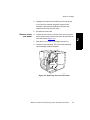
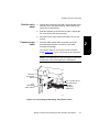
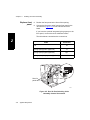


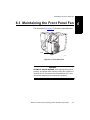
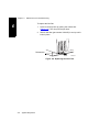
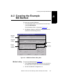
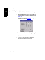
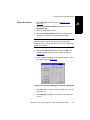
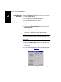

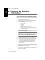


![TSQ Series Getting Started Guide Version C [FR]](http://vs1.manualzilla.com/store/data/006357565_1-ae930521dae4517a45cdbc191dde2ba3-150x150.png)