1
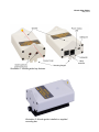
Hinode Solar Guider
May. 2014
Hinode Solar Guider
User Manual
Hutech Corporation
25691 Atlantic Ocean Dr., Unit B-11
Lake Forest, CA 92630
http://hutech.com
Hinode Solar Guider
May. 2014
Introduction
The Hinode Solar Guider is a fully self-contained unit designed to track the sun and control a
motorized astronomical telescope mount. It can be used by visual observers as well as solar
imagers as it removes the inconvenience and tedium of insuring that the sun is properly
centered in the main telescope even if the telescope mount is not accurately polar-aligned.
Whether you are showing the sun to a crowd at a large public event or making a time-lapse
movie of solar prominences, you can now take a break from tending to the telescope tracking.
Unlike autoguiders previously available, the Hinode guider is designed specifically to track the
sun. It is also a low-cost, fully integrated unit which includes optics, guiding sensors, and
computer in a single light-weight and low-power unit. Typical night sky autoguiders require
separate optics (small telescope) and a computer (laptop) to be added, raising costs and
creating a tangle of wiring.
General Autoguiding Concepts
This section describes general autoguiding concepts. If you are familiar with night-time
autoguiders, skip to the next section.
A typical medium to high-end modern astronomical mount includes motors turning at the
proper rate to track stars if properly aligned on the celestial pole.
However, even the most expensive, precision mount will not track an astronomical target
perfectly over the course of a day without some manual correction from you as the target
changes in height above the horizon (refraction effects), or if the polar alignment is a bit off.
Typically, the target will drift in a telescope's view over the course of minutes or hours,
depending on magnification, making it necessary for you to periodically check to see if the
target is centered adequately and make corrections with the mount's hand paddle.
To remove the nuisance of manual guiding, autoguiders electronically watch the target and
“press” the mount's correction buttons for you via the mount's autoguider input port. However,
the tracking performance of the whole system depends on the autoguider and mount system
working together smoothly. Thus, for best overall operation, you need to use a pier or tripod
which is rigid, a mount with minimal “slop” (backlash) in its gears, and a well balanced
telescope load firmly attached to the mount.
For proper operation, the autoguider must be “tuned” to your mount before it can guide it.
This is handled by a calibration (cal) phase in which the autoguider will watch the target, verify
that it can move the mount in all directions, and determine which way, and how much the
mount will move if a correction is made to the mount.
Hinode Solar Guider
May. 2014
Solar Autoguiding Specifics
Solar tracking presents some problems above and beyond those of night-time star tracking.
First, it's difficult to accurately polar align an equatorial mount unless you have set it the night
before using the stars. Second, the sun is often observed near the horizon where refraction is
changing the speed and even the shape of the sun. And third, the sun is moving at a slightly
different rate from the stars – enough so that higher-end mounts provide a special solartracking rate setting.
The Hinode solar guider solves these problems for you by actively watching the image of the
sun, continuously calculating the center position of the sun's disk, and making corrections to
your mount's position.
The Hinode solar guider will even track through light haze. If clouds occasionally completely
block the sun, the guider will audibly alert you to this, and will automatically resume tracking if
the sun is still in view of the guider after the clouds pass by.
For public viewing events, polar alignment is not critical – using your known latitude and a
compass is adequate. While showing the sun to crowds you will know if someone has
bumped your scope enough to move it off the sun so you can make an adjustment if
necessary.
Hinode Solar Guider Components
The Hinode solar guider main components consist of the hand paddle with buttons and
display LED's, optics and electronics box, dovetail mounting bar, and connecting cables:
•
Hand paddle cable (mini-DIN
connectors)
•
Mount autoguider cable (6-pin
telephone-style connectors)
•
USB (standard A to mini-B
connector)
Hinode Solar Guider
May. 2014
Illustration 1: Hinode guider key features
Illustration 2: Hinode guider installed on supplied
mounting bar.
Hinode Solar Guider
May. 2014
Initial Setup
Mechanical Setup
Attach the provided mounting bar to your telescope, parallel to the scope's optical axis. The
mounting bar can be slipped into a Vixen-compatible dovetail slot or screwed directly to a
telescope ring or accessory plate using the screw holes in the plate.
The Hinode solar guider is contained in the optics/electronics box shown above. The
downward-pointing vertical flanges at the front and rear have slots so that the guider can
easily slip on and off the mounting bar. Use the thumbscrews to attach the Hinode guider box
to the mounting bar and tighten with the provided hex wrench if necessary.
For initial setup, there is no need to apply power to the Hinode guider. Simply point your
telescope (properly filtered!) at the sun so it is centered in your eyepiece and/or camera, then
fine-tune the position of the mounted guider using the coarse finder at the top of the Hinode
enclosure. Adjust the pointing direction of the guider so that the image of the hole cast by the
upper front flange is as close as possible to being centered on the yellow target on the rear
flange. The yellow target has been placed to match the internal optical path during factory
alignment.
When mounting the plate to your telescope, note that the plate (and Hinode guider) need not
be exactly aligned with your telescope's optical axis, but a good initial alignment will make
things easier to point your telescope at the sun using the guider's coarse finder as well as
place the sun close to the guider's field of view so that it has the most margin for recovering
from a passing cloud or a bumped scope.
The guider can also be rotated with respect to your eyepiece or camera's view and does not
need its x and y axes aligned with the mount's RA and Dec axes. The autoguider firmware
will compensate for this.
Note: While it may be tempting to do so, DO NOT USE THE HINODE GUIDER AS A
HANDLE! The attachment thumbscrews are not designed to hold the weight of your
telescope!
Hinode Solar Guider
May. 2014
Electronics Checkout
Connect the hand controller to the Hinode's port using the supplied mini-DIN connector cable.
Standard PC keyboard / mouse extension cables can be used to extend the cable length up
to 25 feet.
Connect the Hinode autoguider to your telescope's autoguider input port. The supplied cable
has 6-pin telephone style connector wired to match the semi-standard Losmandy / SBIG ST-4
autoguider interface. Contact Hutech for mounts not specifically supported as listed in the
appendix.
Connect the supplied USB cable to the Power / PC Interface port (mini-USB) of the Hinode
guider. Connect the other end of the cable to any USB compliant power source (laptop
computer, cellphone power supply, portable USB power source, etc.)
Note: The Hinode guider appears to a computer as a serial port device. On initial power-up
the Hinode guider may restart again after a short delay. This is normal. In addition,
depending on your computer settings, the Hinode guider may be reset if another USB device
is plugged into your computer or if your computer goes to sleep. For best results during
normal operation use a power-only USB device to supply power to the Hinode guider.
Once power is connected to the guider, you will hear a 'ding' sound through the Hinode guider
loudspeaker and the hand paddle LED's will also all light briefly. The paddle's level LED's will
then flash the software version level. Example: The top level LED flashes once, the middle
LED flashes twice, and the bottom LED flashes 6 times = Version 1.26.
Hinode Solar Guider
May. 2014
Operating Modes
The Hinode solar guider operates in 3 primary modes – Finder, Calibration (Cal), and Guide.
The Finder mode is meant to assist you in pointing at the sun for both centering your scope
and the guider. No active guiding is performed in this mode of operation. The autoguider
cable need not even be connected to the mount's autoguider input for this mode.
Cal mode allows the guider to train itself to your telescope setup – speed and direction of the
guide controls. The autoguider cable must be connected for this mode. Calibration may take
a few minutes, depending on your mount settings. Once cal has been done, guide mode
allows the Hinode guider to actively track the sun for you.
After a cal has been done, you can freely go back and forth between finder and guide mode
without recalibration. No recalibration is necessary even if the Hinode guider has been turned
off and back on, as long as the physical setup has not been changed, except in the case
when switching to the opposite side of the meridian with a German-equatorial mount.
Operation Steps
In normal use, your solar observing setup procedure will be as follows:
•
Roughly polar align the mount. On a leveled mount, using your latitude to set the
altitude, and a compass to set the azimuth should be adequate.
•
Connect the Hinode guider to your mount, power up the mount (start tracking), and
power up the Hinode guider.
•
Use the Hinode coarse finder to point your scope and Hinode guider at the sun.
•
Calibrate* the guider/mount setup.
•
Upon completing successful calibration, re-center the sun in your eyepiece or camera,
then switch to guide mode, and you're off and running!
* If you have a permanently mounted setup, and if you have previously saved the calibration
parameters (described below), you can skip this step by simply recalling the parameters for
morning (AM) or afternoon (PM) guiding.
Hinode Solar Guider
May. 2014
Finder Mode
When powered up, the Hinode guider starts in Finder
Mode. This mode is used to assist in centering the sun in
your eyepiece or camera. All adjustments to the centering
should be done with your mount controls and with the
mount already tracking.
In Finder Mode, the 3 Level LED's (lower left on paddle)
display the audible tone volume setting. Use the Up and
Down arrow buttons next to the Level LED's to adjust the
volume.
The 5 Directional LED's (lower right on the paddle)
indicate whether the sun is adequately centered in the
guider and of sufficient brightness for guiding. If only the
Center Directional LED is lit, the sun is centered and
bright enough to guide on.
If all 4 outside Directional LED's are lit, either the Hinode
guider is pointed too far away from the sun, or the sun is
too dim to guide on. If the Center Directional LED is lit
along with 2 opposite Directional LED's, one axis is
centered while the other is not. As the telescope is being
centered, one outside LED will stay lit indicating the axis is
approaching center.
Note that if the guider LED's show that it is not centered when the sun is in the desired
position in the telescope, then the guider and scope need to be adjusted to be in better
alignment. In general, the guider will be quite tolerant of an offset because of its wide field of
view, but a good co-alignment insures the best performance in recovering the sun after a
guiding interruption due to clouds.
While already in Finder Mode, pressing the blue Finder button turns the Finder Sound on and
off. The Finder Sound is a tone that increases pitch as you move the sun to the center of your
eyepiece or camera. Using this tone makes it unnecessary to watch the sun's image while
centering the sun – a helpful aid when showing the sun at public events.
Since the centered position for your eyepiece/camera may not be the center of the guider's
field, to set the center point at which the pitch is the highest, first center the sun in the
eyepiece or camera then press and hold the Finder Button down until the Hinode guider
beeps. This mechanical offset setting is stored in memory and will not have to be reset if your
optical alignment is not changed.
Hinode Solar Guider
May. 2014
Calibration Mode
Before the Hinode guider can be used to guide on the sun, it must discover its orientation and
tune itself to the characteristics of the equatorial mount it is used on. This is performed by
running a Calibration cycle as follows:
1. Center the sun in Finder mode until just the center Directional LED is lit.
2. If your mount has guide speed options, set it to a low speed – typically labeled
as 0.5x, 1x, or 2x. In addition, if the mount has an option for solar tracking rate,
you may use it, but it will probably only be helpful only when not guiding with the
Hinode guider (e.g. during cloudy periods).
3. Press the black Calibration button to start the cycle.
•
Once started, the level LED will flicker for about 10 seconds while the
backlash in the mount is taken up. During this time, the Up and Down
arrow keys can be used to adjust the Calibration time. The Calibration
time is indicated on the Level LED's, Low = 10 seconds per axis, Med =
17 seconds, and High = 25 seconds.
•
After the backlash is taken up, the Level LED will flash quickly while the
Calibration process is completed. Pressing any button will abort the
Calibration cycle.
Once the Calibration cycle has started, the Directional LED's will light to
indicate the active autoguider relay outputs. Be careful not to disturb the
mount while performing a Calibration cycle or subsequent poor guiding
may result.
•
After the calibration cycle has completed (up to 2 minutes), the Hinode
guider will return to Finder mode.
The calibration cycle will consist of taking up the backlash in each axis for 4 seconds, then
take a reference measurement of the sun's position. Each axis is then moved for the set
duration and a position measurement is made. The mount is then returned to the reference
position.
If the Calibration cycle is completed successfully, a high pitched beep will sound, and the
Hinode guider will return to Finder Mode. A successful Calibration cycle will store the
parameters in the “Current” memory and will be retained even if the power is removed.
Hinode Solar Guider
May. 2014
If a meridian flip is performed, a Calibration cycle will have to be run again. In order to
prevent having to run a Calibration cycle on setups where the mount configuration or Hinode
guider mounting angle does not change, two memories are provided – AM and PM. To save
the “Current” calibration parameters to one of these memories, simply press and hold either
the AM or PM button down until a tone is heard. This must be done from Finder mode.
To recall the stored calibration parameters from the AM or PM memories, press the Recall
button followed by the desired memory to be copied to the “Current” memory. This must be
done from Finder mode.
If the sun is lost during a calibration cycle, it will be aborted and 3 low beeps will sound with a
pattern of flashing LED's indicating the type of error detected:
LED Pattern
Error Condition
All flashing
No movement detected
Vertical or horizontal line
flashing
Insufficient motion in
indicated direction
Top/Center/Right LED's
flashing
Non-orthogonal motion
detected – more than
15° off.
Hinode Solar Guider
May. 2014
Calibration Troubleshooting
A number of things can cause the calibration to fail. Since autoguiding a mount is a closed
loop system, a problem anywhere in the system can cause a calibration failure. A short list of
the most common problems are listed below:
1. Mechanical problems:
•
Verify the clutches are tight on the mount
•
Adjust out excessive backlash from the mount gears if possible
•
Check that the mount is balanced
•
Verify that cables are not tugging on anything.
•
Verify the Hinode guider is securely mounted to the telescope.
2. Electrical problems:
•
Verify that the autoguider cable is connected, not shorted or contains a broken
wire.
•
Verify the mount has adequate power supply voltage
3. Setup problems:
•
Verify the mount is tracking properly (crossed RA and Dec cables?)
•
Verify that the N/S hemisphere setting is correct for your location
•
Verify that the guide rate setting is between 0.5x and 2x.
4. Environmental problems – Wind and clouds can also cause calibration problems. It is
best to perform a calibration cycle in calm, clear weather and store the parameters for
use under less than ideal conditions.
Hinode Solar Guider
May. 2014
Guide Mode
Once a successful Calibration cycle has been run, the Hinode guider is ready to start guiding.
Place the sun at the desired position in the eyepiece or camera and press the Guide button.
The Level LED will flash slowly to indicate the Hinode guider is guiding. The directional LED's
will show which autoguider relays are being activated.
While guiding, the level LED's indicate the guiding aggressiveness, which can be adjusted
using the Up and Down arrow buttons. High aggressiveness may result in overcorrection, but
will provide the quickest response. Low aggressiveness will minimize unnecessary
corrections caused by seeing and clouds, but will take longer to correct for larger position
errors. Medium aggressiveness is a compromise between the two and is the default setting.
Guiding can be stopped by pressing the Finder button.
If the sun is blocked by heavy clouds while guiding, guiding corrections will stop, but the
Hinode guider will remain in Guide mode. When the clouds clear, the Hinode guider will
return to sun to its original position and continue guiding. When the sun is lost, a decreasing
pitch tone will sound to notify the user that guiding has temporarily stopped. This warning will
sound approximately every 30 seconds until the sun is reacquired. Once the sun is
reacquired, an increasing pitch tone will sound.
Guide Mode Troubleshooting
If the sun continues to drift with guiding engaged, verify the proper calibration parameters are
being used. Remember that a Calibration cycle must be performed for the side of the
meridian that the mount is being used on.
If the above point has been verified, check all of the factors in the CalibrationTroubleshooting
section. The same problems which cause calibration to fail can cause guiding problems.