1
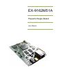
EX-9162M51A
Powerful Single Board
User Manual
EX-9162M51A SBC User Manual
Copyright Notice
Copyright ©2009
All rights reserved.
Reproduction without permission is prohibited.
Disclaimer
Information in this document is subject to change without notice and does not
represent a commitment.
We provides this document “as is”, without warranty of any kind, either
expressed or implied, including, but not limited to, its particular purpose. We
reserves the rights to make improvements and/or changes to this manual, or
to the products and/or the programs described in this manual at any time.
Information provided in this manual is intended to be accurate and reliable.
However, we assumes no responsibility for its use, or for any infringements on
the rights of third parties that may result from its use.
The product might include unintentional technical or typographical errors.
Changes are periodically made to the information herein to correct such errors,
and these changes are incorporated into new editions of the publication.
Safety Information
Electrical safety
z
z
z
z
z
z
Version.: V1.0
Page 1 Total 95
To prevent electrical shock hazard, disconnect the power cable from the
electrical outlet before relocating the system.
When adding or removing EX-9162M51A to or from the system, ensure that
the power cables for the EX-9162M51A are unplugged before the signal
cables are connected. If possible, disconnect all power cables from the
existing system before you add a EX-9162M51A.
Before connecting or removing signal cable from the single board, ensure
that all power cables are unplugged.
Seek professional assistance before using an adapter or extension cord.
These EX-9162M51A could interrupt the grounding circuit.
Make sure that your power supply is set to the correct voltage in your area.
If you are not sure about the voltage of the electrical outlet you are using,
contact your local power company.
If the power supply is broken, do not try to fix it by yourself. Contact a
qualified service technician or your retailer.
EX-9162M51A SBC User Manual
Operation Safety
z Before installation, please carefully read all the manuals that came with the
package.
z Before using the product, make sure all cables are correctly connected and
the power cables are not damaged. If you detect any damage, contact your
dealer immediately.
z To avoid short circuits, keep paper clips, screws and staples away from
connectors, slots, sockets and circuitry.
z Avoid dust, humidity, and temperature extremes. Do not place the product in
any area where it may become wet.
z Place the product on a stable surface.
z If you encounter technical problems with the product, contact a qualified
service technician or your retailer.
The symbol of the crossed out wheeled bin indicated that the product
(electrical and electronic equipment) should not be placed in
municipal waste. Check local regulations for disposal of electric
products.
Caution!
Packing List
Before you begin installing your single board, please make sure the following
materials as attached:
z 1 x EX-9162M51A Single Board
z 1 x USB A type (female) to Mini USB A type (male) converter
z 1 x CD with User Manual, Driver, Software Tools
z 1 x Warranty card
z 1 x Earphone Set
If any of the above item is damaged or missed, please contact your retailer.
Revision History
Date
2010-07-22
Version.: V1.0
Page 2 Total 95
Match
Revised Location
Revision
First Release
Author
Sara, Hellen,
Jason, Janice
EX-9162M51A SBC User Manual
CONTENTS
Copyright Notice................................................................................................................ 1
Disclaimer ......................................................................................................................... 1
Safety Information ............................................................................................................. 1
Electrical safety.......................................................................................................... 1
Operation Safety ........................................................................................................ 2
Packing List....................................................................................................................... 2
Revision History ................................................................................................................ 2
Chapter 1 Product Introduction ......................................................................................... 6
1.1 Key Features........................................................................................................ 6
1.2 Specifications ....................................................................................................... 6
1.3 Block Diagram...................................................................................................... 7
1.4 Screw Holes......................................................................................................... 8
1.5 Board Layout and Dimension............................................................................... 9
1.6 Extension Connectors ........................................................................................ 10
1.6.1 Connector Location Diagram ................................................................... 10
1.6.2 Pin Assignment ........................................................................................ 10
1.7 Power Distribution.............................................................................................. 16
1.7.1 Power Consumption................................................................................. 17
Chapter 2 Function Description....................................................................................... 18
2.1 API Function List ................................................................................................ 18
2.2 Power Management ........................................................................................... 19
2.2.1 Overview.................................................................................................. 19
2.2.2 API Function Call ..................................................................................... 19
2.2.3 API Function Description.......................................................................... 19
2.2.4 Application Example................................................................................. 20
2.3 Battery Function................................................................................................. 20
2.3.1 Battery Management................................................................................ 20
2.3.2 Connector ................................................................................................ 20
2.3.3 Charging LED indicator............................................................................ 21
2.3.4 Charging interface.................................................................................... 21
2.4 Audio Function ................................................................................................... 23
2.4.1 Audio Connector ...................................................................................... 23
2.4.2 Audio APIs for EX-9162N51AB ................................................................ 24
2.5 WiFi / Bluetooth Function ................................................................................... 27
2.5.1 WiFi / BT Access...................................................................................... 27
2.5.2 WiFi / Bluetooth API ................................................................................. 34
2.6 KeyPad Function................................................................................................ 36
2.6.1 Introduction .............................................................................................. 36
2.6.2 Connector ................................................................................................ 36
2.6.3 Electrical Parameters............................................................................... 36
2.7 LAN Function ..................................................................................................... 37
2.7.1 Introduction .............................................................................................. 37
2.7.2 LAN Configure ......................................................................................... 37
2.8 SD Card Function .............................................................................................. 40
2.8.1 Connector ................................................................................................ 40
Version.: V1.0
Page 3 Total 95
EX-9162M51A SBC User Manual
2.8.2 SD card identify........................................................................................ 40
2.9 LCD Display Function ........................................................................................ 41
2.9.1 Approved LCD panel................................................................................ 41
2.9.2 Connector ................................................................................................ 42
2.10 Touch Screen Function .................................................................................... 42
2.10.1 Connector .............................................................................................. 42
2.11 USB Host Function........................................................................................... 43
2.11.1 Connector............................................................................................... 43
2.12 USB OTG Function .......................................................................................... 44
2.12.1 Overview................................................................................................ 44
2.12.2 USB OTG Pin definition ......................................................................... 44
2.12.3 Connector .............................................................................................. 44
2.13 Serial Port Function ......................................................................................... 45
2.13.1 Overview................................................................................................ 45
2.13.2 Serial Port Connector............................................................................. 45
2.13.3 RS232 Pin Description........................................................................... 45
2.13.4 Port List.................................................................................................. 45
2.13.5 Electrical Parameters............................................................................. 46
2.14 GPIO Function ................................................................................................. 47
2.14.1 Overview................................................................................................ 47
2.14.2 API Functions......................................................................................... 47
2.14.3 API Function Description........................................................................ 47
2.14.4 An Example to Call APIs ........................................................................ 48
2.15 ADC Function................................................................................................... 49
2.15.1 API Overview ......................................................................................... 49
2.15.2 API Function .......................................................................................... 49
2.15.3 API Function Description........................................................................ 49
2.15.4 An Example to Call APIs ........................................................................ 50
2.16 SPI Interface Function...................................................................................... 51
2.16.1 Introduction ............................................................................................ 51
2.16.2 Electrical Parameters............................................................................. 51
2.16.3 Connectors ............................................................................................ 51
2.16.4 SPI APIs................................................................................................. 51
2.17 I2C Interface Function...................................................................................... 55
2.17.1 Introduction ............................................................................................ 55
2.17.2 I2C Pin Description ................................................................................ 55
2.17.3 I2C Connectors ...................................................................................... 55
2.17.4 I2C APIs................................................................................................. 55
2.17.5 HSI2C APIs............................................................................................ 59
2.18 CAN Bus Function ........................................................................................... 62
2.18.1 Introduction ............................................................................................ 62
2.18.2 Electrical Parameters............................................................................. 62
2.18.3 Pin Description of CAN Bus ................................................................... 62
2.18.4 CAN Bus APIs........................................................................................ 62
Chapter 3 Application Development Guide ..................................................................... 66
3.1 Application Development Architecture................................................................ 66
Version.: V1.0
Page 4 Total 95
EX-9162M51A SBC User Manual
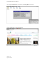
3.2 How To Connect with PC ................................................................................... 66
3.2.1 Install the Software Tool Microsoft ActiveSync ......................................... 66
3.2.2 Run and Configure the Microsoft ActiveSync ........................................... 67
3.2.3 Connection............................................................................................... 68
3.3 How To Download Files into EX-9162M51A....................................................... 71
3.4 SDK Install / Uninstall......................................................................................... 72
3.4.1 Install SDK ............................................................................................... 72
3.4.2 Uninstall SDK........................................................................................... 72
3.5 APIs Summary ................................................................................................... 73
3.5.1 Overview.................................................................................................. 73
3.5.2 Headers ................................................................................................... 73
3.5.3 API Member ............................................................................................. 73
3.5.4 API Description ........................................................................................ 74
3.5.5 An Example to call APIs in C/C++ ............................................................ 75
Appendix A: LCD Panel Selection & Rotation Setting ..................................................... 80
A.1 Configure EX-9162M51A and Run Up ............................................................... 80
A.2 Panel Selection.................................................................................................. 83
A.3 Panel Rotation ................................................................................................... 84
A.4 Save and Launch............................................................................................... 84
Appendix B: iMX51 image file(NK) Download ................................................................. 86
B.1 Setup and Configure.......................................................................................... 86
B.2 Download NK..................................................................................................... 89
Appendix C: EX-9162M51A IP Setting ............................................................................ 91
Appendix D: Terminal Tool Setting .................................................................................. 93
Version.: V1.0
Page 5 Total 95
EX-9162M51A SBC User Manual
Chapter 1 Product Introduction
1.1 Key Features
EX-9162M51A is designed with Freescale’s iMX51 CPU based on powerful ARM Cortex
A8™ core.
z
Excellent ARM Cortex A8 Multi-Media Platform
z
Multiple IO Ports, Easy Extended for various application
z
Build in Wireless
z
Compact Size for Multiple Application
z
Low Power Consumption and Power Management
z
Fanless
z
WinCE Ready
z
API / Lib Provided
z
SDK Provided
z
Wide Input Voltage
z
Low Cost
1.2 Specifications
●
●
●
●
●
●
●
●
●
●
●
●
●
●
●
●
●
●
●
●
●
●
●
●
●
●
Freescale iMX51 Cortex A8 800MHz CPU
Build In Cache: 32KB I-Cache and 32KB D-Cache (L1),256KB cache (L2)
DRAM: DDR-II 256MB SDRAM on board
NAND Flash: 512MB up to 1GB Flash
Auto Power Management: for power saving
TV out: Support composite Video out and Y/C S-Video out
LCD: Dual Display Support, one is 24 bit TFT LCD, the other one is18-bit TFT LCD
* Optional LVDS or VGA convert boards for different display
Touch Panel: 4 way touch control
Ethernet : 100/10M Ethernet, Support RJ45 connector (UPT)
USB 2.0: USB OTG and USB Host (ULPI)
SD: SD Card socket on board
Bus type: Expansion EIM system bus
SPI Port: CSPI bus for extension board
I2C : I2C Port
I2S : one for extension port, the other one for Bluetooth
Audio: Audio Processor on board
Keypad: 6x4 matrix keyboard
COM Port: RS232 x 2 and one UART
CAN: CAN bus on board
GPIO: 10 bit 3V3 GPIO, 5V tolerance
ADC port: 8 Ch 12-bit Analog to Digital Converter
Camera Port: 2 Ch, up to 8Mpixel @ 15fps, up to 133Mpixel/sec
WiFi / Bluetooth, alternatively: WiFi 802.11 b/g/n, or Bluetooth 2.0/3.0, one Antenna
port
Power Requirement: 6.5V ~ 35V power or 5V Supply or Li-Battery Supply
Battery Charger : Build In
Dimension: 94mm x 65mm
Operating Temperature: -20℃ to 70℃ (-4℉ ~ 158℉)
*We also provide daughter board - EX-9162X51AB for more IO extension, for more
information, contact our customer service now!
Version.: V1.0
Page 6 Total 95
EX-9162M51A SBC User Manual
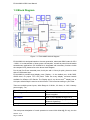
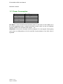
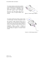
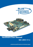
1.3 Block Diagram
Figure 1-1: EX-9162M51A block diagram
EX-9162M51A is designed based on the new-generation, advanced ARM Cortex-A8 CPU
– iMX51. It is characteristic of lower power consumption, as well as powerful multi-media
entertainment applications. EX-9162M51A is integrated with necessary functions inside
the compact PCB, please refer to the above block diagram.
Port A and Port B are extended ports, 2x42 pins with 1.27mm pin-pitch, placed on both
side of PCB bottom layer.
EX-9162M51A provides dual display ports, Display 1 is the default port, 24-bit RGB,
CMOS level, for proper TFT LCD panel. There are many display converter boards
available for different LCD Panels. The Display port 2 can be set as 2nd display port or
LAN port, default Disp2 is used as a LAN function. This is fixed according to your order.
There are multiple power inputs, Wide Range 6.5~35Vdc, 5V direct, or 3.6V Li-battery
power supply…etc,
Type of Power Input
When to use
Wide Range
Please use DCIN on Port B, range 6.5Vdc ~
35Vdc is applied.
Wall adapter
5Vdc +/-5% is applied through Port B.
USB
Use USB Power, 5V input (Without WiFi or
Bluetooth Operation)
Battery
3.6Vdc ~ 4.2Vdc Li Battery on VBAT1 port
The total power dissipation of usual operation is around 300~400mA@ 5V only, but the
Version.: V1.0
Page 7 Total 95
EX-9162M51A SBC User Manual
actual power dissipation depends on how many Hardware Engines are used inside iMX51
CPU.
Basically, power dissipation is auto adjusted by power management chip and CPU. When
CPU runs at high speed, CPU loading will be detected and measured, with core voltage
goes up a little bit.
1.4 Screw Holes
Please ensure your EX-9162M51A single board in nice condition, no broken parts and
placed in the case correctly.
Place four (4) screw holes to fix into your casing, 2.5mm each, indicated in red circles at
the figure below. Screws are designed to fix the EX-9162M51A PCB, and increase Ground
connection, as well as avoid EMI issue.
Figure 1-2: EX-9162M51A SBC’s Screw Holes
4 screws (red color) be connected to Ground
Do not over fasten the screws and use the right screw driver.
Version.: V1.0
Page 8 Total 95
EX-9162M51A SBC User Manual
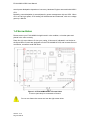
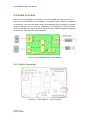
1.5 Board Layout and Dimension
Figure 1-3 EX-9162M51A PCB Dimension and Profile
Version.: V1.0
Page 9 Total 95
EX-9162M51A SBC User Manual
1.6 Extension Connectors
EX-9162M51A provides 2 extended connectors, Port A (J5) and Port B (J6), for the
function of I2C, SPI, GPIO, ADC, UART, USB, S-Video Signals, Key pad, and so on. The
function’s detailed description will be shown on Chapter 2. Port J7 is display port 1, and J4
is the mirror to J7 pins(left/right reversed) , placed on Top layer. J5,J6 and J7 are used to
plug with Carrier Board EX-9162X51AB directly.
1.6.1 Connector Location Diagram
Figure1-4:Connector Location Diagram
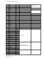
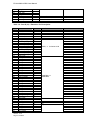
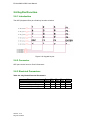
1.6.2 Pin Assignment
Table 1-1: Port A(J5)-Extension Pin Description
Pin
1
2
3
4
5
6
7
8
9
10
11
12
Name
USB HS DP
USB HS DM
5V
GND
RXD1
TXD1
RTS1
CTS1
RXD2
TXD2
RTS2
CTS2
Version.: V1.0
Page 10 Total 95
Sym
I/O
I/O
PO
GND
I
O
I
O
I
O
I
O
Port Function
Remark
USB Host
USB Host port
5V Power Output
Output from DC2DC
UART1, System Debug port
iMX51 UART port 1
UART2, Optional, provided only
when no Bluetooth
iMX51 UART port 2
EX-9162M51A SBC User Manual
13
14
15
16
17
18
19
20
21
22
23
24
25
26
27
28
29
30
31
32
33
34
35
36
37
38
39
40
41
42
43
44
45
46
47
48
49
50
51
52
53
54
55
56
57
58
59
60
61
62
63
64
65
66
67
68
69
70
71
72
xAi0
xAI1
xAI3
xAI2
xDIO1
xDIO0
CSPI1_MOSI
CSPI1_MISO
CSPI1_RDY
CSPI1_SCLK
NC
CSPI1_SS1
3V3
xAI4
xAI5
xDIO2
xDIO9
xDIO8
xDIO3
xDIO4
xDIO6
xDIO7
xDIO5
GND
OWIRE
NC
3V3
GND
EIM_DA5
EIM_DA2
EIM_DA3
EIM_DA4
EIM_DA7
EIM_DA0
EIM_DA1
EIM_DA6
EIM_DA13
EIM_DA8
EIM_DA9
EIM_DA10
EIM_DA15
EIM_DA12
EIM_DA11
EIM_DA14
EIM_A19
EIM_A18
EIM_A17
EIM_A16
EIM_A21
EIM_A22
EIM_A23
EIM_A20
EIM_A25
EIM_A24
EIM_BCLK
EIM_OE
EIM_EB1
EIM_CSS
EIM_LBA
EIM_WAIT
Version.: V1.0
Page 11 Total 95
Ai
Ai
Ai
Ai
I/O
I/O
O
I
X
O
O
PO
Ai
Ai
I/O
I/O
I/O
I/O
I/O
I/O
I/O
I/O
GND
I/O
PO
GND
I/O
I/O
I/O
I/O
I/O
I/O
I/O
I/O
I/O
I/O
I/O
I/O
I/O
I/O
I/O
I/O
I/O
I/O
I/O
I/O
I/O
I/O
I/O
I/O
I/O
I/O
O
O
O
O
O
I
2.5V, 12bit ADC
2.5V, 12bit ADC
2.5V, 12bit ADC
2.5V, 12bit ADC
2.7V, In/out, Set by SW, API
I2.7V, in/out, Set by SW,API
2.7V
2.7V
2.7V
2.7V
3.15V, Supply from PMIC
2.5V, 12bit ADC
2.5V, 12bit ADC
In/out Set by SW,API
In/out Set by SW,API
In/out Set by SW,API
In/out Set by SW,API
In/out Set by SW,API
In/out Set by SW,API
In/out Set by SW,API
In/out Set by SW,API
For one wire IO control
3.15V, Supply from PMIC
Expansion Bus
Can be EIM A19-A25 or
Extend GPIO, controlled by SW
Expansion Bus
Analog Input pins
GPIO
SPI1
EX-9162M51A SBC User Manual
73
74
75
76
77
78
79
80
EIM_RW
EIM_EB0
EIM_CS1
EIM_CS0
RESETIO
TRCTL_PATA
GPIO1_8
GPIO1_7
O
O
O
O
O
O
I/O
I/O
IO Reset Signal, active L
As Extend GPIO, controlled by
GPIO, from iMX51
GPIO, from iMX51
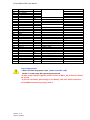
Table 1-2: Port B (J6) - Extension Pin Description
Pin
1
2
3
4
5
6
7
8
9
10
16
11
12
13
14
15
17
18
19
20
21
22
23
24
25
26
27
28
29
30
31
32
33
34
35
36
37
38
39
40
41
42
43
44
45
46
47
48
49
50
51
Name
ADCIN
ADCIN
RESETIO
POR
UART3.TXD
UART3.RXD
SER_DISP2_CS
DISPB2_SER_RS
DISPB2_SER_DIO
DISPB2_SER_DIN
DISPB2_SER_CLK
SER_DISP1_CS
DISPB1_SER_RS
DISPB1_SER_DIO
DISPB1_SER_DIN
DISPB1_SER_CLK
CSI1_D11
CSI1_D10
CSI1_D13
CSI1_D12
CSI1_D15
CSI1_D14
CSI1_D17
CSI1_D16
CSI1_D19
CSI1_D18
CSI1_PIXCLK
CSI1_MCLK
CSI1_VSYNC
CSI1_HSYNC
CSI2_D18
CSI2_D15
CSI2_D13
CSI2_D17
CSI2_D12
CSI2_D16
CSI2_D19
CSI2_D14
CSI2_HSYNC
CSI2_VSYNC
GPIO_CAM2_LPM
CSI2_PIXCLK
I2C1_CLK
I2C1_DAT
CAM_RESET_B
CAM1_LPM
KEY_COL0
KEY_COL1
KEY_COL2
KEY_COL3
KEY_COL4
Version.: V1.0
Page 12 Total 95
Sym
Ai
Ai
O
I
O
I
O
O
I/O
I
O
O
O
I/O
I
O
I
I
I
I
I
I
I
I
I
I
I
O
I
I
I
I
I
I
I
I
I
I
I
I
O
O
O
I/O
O
O
Port Function.
DISP1, 2 for Series LCD
CAMERA 1 &
CAMERA 2
I2C
3V
3V
KeyPad
Remark
EX-9162M51A SBC User Manual
52
53
54
55
56
57
58
59
60
61
62
63
64
65
66
67
68
69
70
71
72
73
74
75
76
77
78
79
80
81
82
83
84
KEY_COL5
KEY_ROW0
KEY_ROW1
KEY_ROW2
KEY_ROW3
1.8V
5V
GND
3V3
CAN1CAN1+
AUD4_RXD
AUD4_TXD
AUD4_TXFS
AUD4_TXC
GND
OWIRE_LINE
AUDIO_AGND
ON_OFF
AUDIO_LOUT_R
AUDIO_LIN_R
AUDIO_LOUT_L
AUDIO_LIN_L
VDO_C
VDO_Y
AGND_RGB
Video_out
VOA
COIN_CELL_BAT
GND
DCIN
WALL_5V_IN
5V
PO
PO
GND
PO
I
O
O
O
AGND
I
Ao
Ao
AGND
Ao
PO
PI
GND
PI
PI
PO
3.15V
CAN
I2S4, direct input to iMX51
Same above
Same above
Same above
ON/OFF PMIC
Audio Output, R Ch
Audio Input, R Ch
Audio Output, L Ch
Audio Input, L Ch
S-Video. Color
S-Video, Lumin.
Video GND
Video Composite Signal
Power Supply, by SW
Coin Cell Battery, Input
6.5V~35Vdc Input
Vin to PMIC
DC2DC output, 5V
Toggle Switch
Short with 5V through R97
Up to 2.5A
Power Supply Notes:
* When use wide range power input , please short R97 (=0R).
DC2DC is a wide range DC input and generates 5V.
*If 5Vdc power supply is applied, please connect to WALL_5V_IN directly. (Port B,
J6, pin 83)
*If you will use battery, please apply Li-ion Battery, 3.6V~4.2V. (BAT1 connector)
EX-9162M51A has Battery Charger built in.
Version.: V1.0
Page 13 Total 95
EX-9162M51A SBC User Manual
Table 1-3: J4 (Display1) Pin Description
Pin
1
2
3
4
5
6
7
8
9
10
11
12
13
14
15
16
17
18
19
20
21
22
23
24
25
26
27
28
29
30
31
32
33
34
35
36
37
38
39
40
Name
DISP1_DAT0
DISP1_DAT1
DISP1_DAT2
DISP1_DAT3
DISP1_DAT4
DISP1_DAT5
DISP1_DAT6
DISP1_DAT7
GND
DISP1_DAT8
DISP1_DAT9
DISP1_DAT10
DISP1_DAT11
DISP1_DAT12
DISP1_DAT13
DISP1_DAT14
DISP1_DAT15
GND
DISP1_DAT16
DISP1_DAT17
DISP1_DAT18
DISP1_DAT19
DISP1_DAT20
DISP1_DAT21
DISP1_DAT22
DISP1_DAT23
GND
3V
3V
HSYNC
VSYNC
DRDY
PCLK
CONTRAST
LEDLED+
TScreen_LEFT
TScreen_BOTTOM
TScreen_RIGHT
TScreen_TOP
Version.: V1.0
Page 14 Total 95
Sym
O
O
O
O
O
O
O
O
PG
O
O
O
O
O
O
O
O
PG
O
O
O
O
O
O
O
O
Ground
PO
PO
O
O
O
O
O
I/O
I/O
I/O
I/O
Description
B0: lsb
B1
B2
B3
B4
B5
B6
B7: msb
G0: lsb
G1
G2
G3
G4
G5
G6
G7: msb
R0: lsb
R1
R2
R3
R4
R5
R6
R7: msb
LCD power; No supply LCD Backlight
LCD power. No supply LCD Backlight
DE signal for LCD
H: turn on LCD backlight; L: off
LED negative
LED positive
Touch Screen
EX-9162M51A SBC User Manual
Table 1-4: J2 (Display2) Pin Description
Pin
Name
1
2
3
4
5
6
7
8
9
10
11
12
13
14
15
16
17
18
19
20
21
22
23
24
25
26
27
28
29
30
GND
DISP2_DAT0/ETH_RDATA3
DISP2_DAT1
DISP2_DAT2/ETH_RX_ER
DISP2_DAT3
DISP2_DAT4
DISP2_DAT5
DISP2_DAT6/ETH_TDATA1
DISP2_DAT7/ETH_TDATA2
DISP2_DAT8/ETH_TDATA3
DISP2_DAT9/ETH_TX_EN
DISP2_DAT10/ETH_COL
DISP2_DAT11/ETH_RX_CLK
DISP2_DAT12/ETH_RX_DV
DISP2_DAT13/ETH_TX_CLK
DISP2_DAT14/ETH_RDATA0
DISP2_DAT15/ETH_TDATA0
DISP2_DAT16
DISP2_DAT17
GND
ETH_RDATA2
ETH_MDC
ETH_MDIO
ETH_CRS
ETH_RDATA1
3V
GND
LANintr
ETH_RESET_B
Version.: V1.0
Page 15 Total 95
Sym
Description
EX-9162M51A SBC User Manual
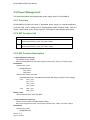
1.7 Power Distribution
Figure 1-5: Block Diagram of Power Distribution
PMIC: This is the main power management IC, supplying multi-channel power to the
entire board. It supplies CPU core voltages and fine tune its voltage dynamically according
to CPU performance and loading. PMIC can accept many power inputs, such as USB,
5V_Wall adapter and Li-ion Battery. These Power inputs are input directly to PMIC.
5V_Wall isn’t dedicated to connector, you could use it at Port_B (J6) pin 83 USB and
Battery have dedicated IO connector, named USB1 and BAT1. USB1 is located at the
front board edge, while BAT1 is placed at rear board edge.
If user has 5V DC power supply, connect to J6/Pin83 and supply entire board. When you
have another voltage, Wide Range DC to DC circuit is needed.
6.5V~35V Wide Range DC to DC converter: Wide range Power Input provides
6Vdc to 35Vdc, that is an optional function for some application. Also you could input the
power directly onto DCIN1 connector. For easy extension on Board to Board connection,
you could use J6/pin82. This module outputs 5Vdc. This 5Vdc could supply voltage to
5V_wall through R97 0R, that is a default connecting part.
BAT1: This is a connector for 3.6V Li-Ion Battery, 3-pin, extra pin for thermal sensor of
Li-Battery. NC (no connection) on no use. Battery capacity depends on user’s application.
You may or may not connect a Li Battery to BAT1 connector. Usually the battery is
1600mA/hr Li-Ion.
USB Power Supply: Usually, USB could supply 100mA/500mA @5V, from PC host to
devices, PC could supply EX-9162M51A 5V power supply through USB, only when WiFi /
Version.: V1.0
Page 16 Total 95
EX-9162M51A SBC User Manual
Bluetooth is absent.
1.7.1 Power Consumption
Mode
Run
User Idle
System Idle
Suspend
Power Off
Total Power
350mA@5V
NA
NA
NA
NA
Run Mode: It is the normal/functional operating mode. At this mode, the CPU ARM runs in
its normal operational mode. It needs more power current, when you turn on hardware
engines of iMX51 CPU as H264 codec engine … etc.
Stop Mode: In this mode, all system clocks are stopped. PLLs are stopped. Power gating
can be done on ARM platform, IPU,VPU and EMI. Synchronization of the CKIL clock is
bypassed.
Version.: V1.0
Page 17 Total 95
EX-9162M51A SBC User Manual
Chapter 2 Function Description
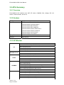
The following API list could be used for EX-9162M51A and EX-9162N51AB.
EX-9162N51AB is the incorporation of the CPU board EX-9162M51A and its IO carrier
board EX-9162X51AB. EX-9162X51AB expands many useful IO functions for
EX-9162M51A. Some API modules are implemented only when EX-9162X51AB is
available.
Detailed information about EX-9162X51AB, please refer to EX-9162X51AB User Manual.
2.1 API Function List
Table 2-1: API Function List
Function
EX-9162M51A
EX-9162N51AB
Power Management
Y
Y
Inner Adj. Voltages
Y
N
Battery
Y
Y
RTC
Y
Y
LCD display
Y
Y
Touch screen
Y
Y
Audio
Y
Y
Audio MUX
N
Y
Video
N
Y
SD/MMC
Y
Y
Keyboard
Y
Y
USB OTG
Y
Y
LAN
Y
Y
WiFi
Y
Y
Bluetooth
Y
Y
Serial Port
Y
Y
6 COM PORTS
N
Y
GPIO
Y
Y
ADC
Y
Y
SPI Interface
Y
Y
I2C Interface
Y
Y
CAN Bus
Y
Y
SRAM
N
Y
433/866/915 RF
N
Y
GPS
N
Y
3G Module
N
Y
GSM&GPRS
N
Y
Version.: V1.0
Page 18 Total 95
EX-9162M51A SBC User Manual
2.2 Power Management
This section describes the programmable power supply APIs for EX-9162M51A.
2.2.1 Overview
EX-9162M51A provides two kinds of adjustable power supply for external application,
VOA and VOB, whose voltage can be programmable within a limited range. VOA can
supply 4-step voltage under 150mA capacity; VOB supply 2-step voltages under 50mA.
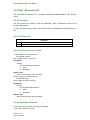
2.2.2 API Function Call
Interface
1
BOOL SetVoltage(REGULATOR_VREG
regulator,REGULATOR_VREG_VOLTAGE voltage)
2
BOOLGetVoltage(REGULATOR_VREG
regulator,REGULATOR_VREG_VOLTAGE* voltage)
2.2.3 API Function Description
1. CEX-9162M51ACtl::SetVoltage
Set outside for the voltage
BOOL SetVoltage(REGULATOR_VREG regulator,REGULATOR_VREG_VOLTAGE voltage)
Parameters
REGULATOR_VREG
[in]Specified pin.
VOA_VREG
VOB_VREG
REGULATOR_VREG_VOLTAGE
[in]Designated VOA, VOB side were outside the range of values for the voltage,
VOA:
VOA_2_30V
VOA_2_50V
VOA_2_775V
VOA_3_000V
VOB:
VOB_1_80V
VOB_2_90V
Return value
Set successful return true, else false.
2. CEX-9162M51ACtl::GetVoltage
Get the current value of foreign supply voltage.
BOOL GetVoltage(REGULATOR_VREG regulator,REGULATOR_VREG_VOLTAGE* voltage)
Parameters
REGULATOR_VREG
[in]Specified pin.
Version.: V1.0
Page 19 Total 95
EX-9162M51A SBC User Manual
VOA_VREG
VOB_VREG
REGULATOR_VREG_VOLTAGE
[out]Designated VOA, VOB side were outside the range of values for the voltage,
VOA:
VOA_2_30V
VOA_2_50V
VOA_2_775V
VOA_3_000V
VOB:
VOB_1_80V
VOB_2_90V
Return value
Returns true for success, else false.
2.2.4 Application Example
VOA voltage value is set to 2.5V, the code is as follows:
REGULATOR_VREG
nPort;
REGULATOR_VREG_VOLTAGE
nVol;
nPort = VOA_VREG;
nVol.voa = VOA_2_50V;
m_pDvcBase->SetVoltage(nPort, nVol);
For VOA, on the voltage value, the code is as follows:
m_pDvcBase->GetVoltage(nPort,&nVol);
2.3 Battery Function
2.3.1 Battery Management
--EX-9162M51A supports Battery. Please use Li-ion Battery, 3.6V~4.2V
--EX-9162M51A has Battery Charger inside.
2.3.2 Connector
BAT1 is a 3-pin connector with housing, for external battery input.
Version.: V1.0
Page 20 Total 95
EX-9162M51A SBC User Manual
Figure 2-1:
Battery Connector
Pin1 is the positive terminal of the battery, the current sensing point. The supply voltage of
the battery is sensed through an ADC. The current of battery can be read back via the
ADC by monitoring the voltage drop over the sensing resistor.
Pin2 is battery ground.
Pin3 is used to read out the battery pack thermistor. A resistor divider network should
assure the resulting voltage within the ADC input range, in particular when the thermistor’s
inspection function is being used.
1.
2.
Make sure the positive(pin1) and negative pole(pin2) on the right
position, not on the contrary.
After a long time of use, please check the voltage of the battery.
When the voltage is too low, please replace the battery!
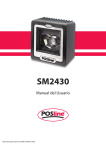
2.3.3 Charging LED indicator
The driver at CHRGLED serves as the
trickle (sign of life) LED and will be
activated when standalone charging is
started, and will also remain on when
the device is powered on, until the
charger is programmed by SPI.
Figure 2-2: Charging LED Indicator
2.3.4 Charging interface
The charger supports charging from a wall charger or from a USB host.
Version.: V1.0
Page 21 Total 95
EX-9162M51A SBC User Manual
The charger interface provides linear operation
via an integrated DAC at programmable current
levels. It incorporates a standalone trickle
charge mode, in case of a dead battery with
dual LED indicator driver. Over-voltage,
short-circuit, and under-voltage detectors are
included as well as charger detection and
removal.
Figure 2-3: Wall Charger Interface
The charger includes the necessary circuitry to allow
for USB charging. The battery management system
also provides a battery presence detector, and a
converter from A to D that serves for measuring the
charge current, battery and other supply voltages, as
well as for measuring the battery thermistor and die
temperature. Finally, a system is included for
monitoring the current drawn from, or charged into
the main battery for support of a Coulomb Counter
function.
Figure 2-4: USB Charging Interface
Version.: V1.0
Page 22 Total 95
EX-9162M51A SBC User Manual
2.4 Audio Function
Audio Function is separated into two portion, one is EX-9162M51A’s audio processor, the
other one is EX-9162X51AB’s audio multiplexer. The following audio processor is welded onto
EX-9162M51A. The Low Power Stereo Codec with Headphone Amp is designed for portable
products needing line-in, mic-in, line-out, headphone-out, and digital I/O. It is able to achieve
ultra low power with very high performance and functionality. Capless headphone design and
an internal PLL help cost down the whole system.
Figure 2-5: EX-9162M51A’s Audio Block Diagram
2.4.1 Audio Connector
Figure 2-6: EX-9162M51A Audio Connector
Version.: V1.0
Page 23 Total 95
EX-9162M51A SBC User Manual
2.4.2 Audio APIs for EX-9162N51AB
2.4.2.1 Audio Multiplexer Overview
There are Audio Input Multiplexer and Output Multiplexer circuit in the EX-9162N51AB
single board. Audio Input Multiplexer supports 4-channel audio line input, inner
Microphone and 3G/GSM audio path. And audio output multiplexer has two input paths
from EX-9162M51A audio output and 3G/GSM voice output. 3G/GSM has only one single
audio channel.
4-channel external audio Line input, and internal audio channels are designed for system
debug port, GPS port …etc. Totally six ways of Audio input channel provide switching,
including the system, GSM, Line1 \ Line2 \ Line3 \ Line4; Two-way output channel,
including systems, GSM, and volume control.
2.4.2.2 API
Function
Interface
1
BOOL SetAudioIn(int channelIn)
2
BOOL SetSpeakerCh(int channelOut)
3
BOOL SetAudioVolume(int nLVol,int nRVol)
4
BOOL GetAudioVolume(int& nLVol,int& nRVol)
2.4.2.3 Audio API Description
1. CEX-9162M51ACtl::SetAudioIn
Set six input channels.
BOOL SetAudioIn(int channelIn)
Parameters
channelIn
[in] Specified channel number.
0:
system
1:
Line1
2:
Line2
3:
Line3
4:
Line4
5:
GSM
Return value
Set successful return true, else false.
2. CEX-9162M51ACtl::SetSpeakerCh
Set output channel.
Usually select the input channel for the system, Line1 \ Line2 \ Line3 \ Line4, the
output channel is set to the system, only when you select GSM as the input channels
are required to set the output channel for the GSM
Version.: V1.0
Page 24 Total 95
EX-9162M51A SBC User Manual
BOOL SetSpeakerCh(int channelOut)
Parameters
channelOut
[in] Specified channel number.
0:
system
1:
GSM
Return value
Set successful return true, else false.
3. CEX-9162M51ACtl::SetAudioVolume
Set the output volume.
BOOL SetAudioVolume(int nLVol,int nRVol)
Parameters
nLVol
[in] Specify the value of the output volume of the left channel, in the 0-31 range.
nRVol
[in] Specify the value of the output volume of the right channel, in the 0-31 range.
Return value
Set successful return true, else false
4. CEX-9162M51ACtl::GetAudioVolume
Get the output volume.
BOOL GetAudioVolume(int& nLVol,int& nRVol)
Parameters
nLVol
[out]The volume of the left channel value, the range of 0-31
nRVol
[out] Right channel volume value, the range of 0-31 range.
Return value
Get successful return true, else false
2.4.2.4 An Example to Call APIs
If the sound channel to switch to the system, the code is as follows:
m_pDvcBase->SetAudioIn(0);
m_pDvcBase->SetSpeakerCh(0);
If the voice switch to the Line1 channel, the code is as follows:
m_pDvcBase->SetAudioIn(1);
m_pDvcBase->SetSpeakerCh(0);
If the switch to the GSM voice channel, the code is as follows:
m_pDvcBase->SetAudioIn(5);
m_pDvcBase->SetSpeakerCh(0);
Version.: V1.0
Page 25 Total 95
EX-9162M51A SBC User Manual
Set the system volume to 20db, the code is as follows:
m_pDvcBase->SetAudioVolume(20,20);
Version.: V1.0
Page 26 Total 95
EX-9162M51A SBC User Manual
2.5 WiFi / Bluetooth Function
EX-9162M51A offers a full-featured WiFi 802.11b/g/n or Bluetooth V2.1+EDR dual radio
module that simultaneously provides WiFi and Bluetooth connections.
And it supports single antenna configuration for WiFi and Bluetooth; for state-of-the-art
WiFi-Bluetooth co-existence and VoIP optimizations; and EEPROM and full RF front-end
integrated for WiFi and Bluetooth.
WiFi has same frequency band as Bluetooth, and shares the same 2.4GHz antenna with
bluetooth. Therefore, WiFi or Bluetooth is applied alternatively at one time, please select
one before you place order.
Please be reminded that 2.4GHz antenna must be assembled
before using WiFi or Bluetooth.
2.5.1 WiFi / BT Access
2.5.1.1 WiFi Access
Please prepare the necessary hardware before WiFi connection.
Table 2-2: Hardware Required for WiFi / BT access
Required Hardware
Description
WiFi Access Point
Antenna
Use the standard WiFi antenna and connect it to the
antenna interface. For more information about the
connection between the module and the antenna, please
refer to Figure 2-7: Antenna Connection.
Test Software
The following two DLL files are necessary when you are going to use WiFi/Bluetooth
Module.
Table2-3: Software Required for WiFi test
Requirement
ufsdio.dll and
ufmp.dll
Version.: V1.0
Page 27 Total 95
Description
Driver .dll file of WiFi module has been
included in the WinCE OS.
EX-9162M51A SBC User Manual
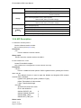
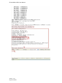
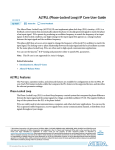
Test Procedure
Please follow the guide below to test the WiFi module step by step. .
1. Power on the EX-9162N51AB board.
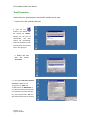
2.
Click
the
icon
located in the WinCE task
bar. Usually the “UFMP1”
dialogue box will pop out
automatically,
module
will
and
WiFi
automatically
search the available network
around and list them. Please
refer to the right figure.
3. Select one and
click the button
“Connect”
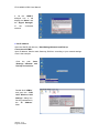
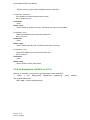
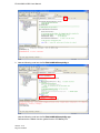
4. In the opened “Wireless Network
Properties” dialog box, set
“Encryption” as “TKIP” and
“Authentication” as “WPA2-PSK”. If
your wireless access point has been
set a password, input the “Network
key”, then click the button “OK”, the
WiFi module will access the network
Version.: V1.0
Page 28 Total 95
EX-9162M51A SBC User Manual
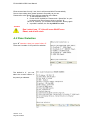
5. On the “UFMP1”
dialogue box, it will
display the “Status” and
the “Signal Strength”
of
the
connected
network.
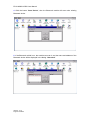
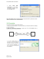
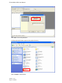
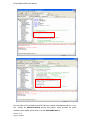
6. Set IP address
Open the WinCE OS directory “Start\Settings\Network and Dial-up
Connections\UFMP1”,
Input IP address, Subnet mask, Gateway, DNS etc. according to your network settings.
Here is the example.
Click the path “Start
\Settings \Network and
Dial-up Connections”
Double click “UFMP1”
and open the “’CSR
UniFi Wireless LAN
Settings” dialog box.
Set the parameters in
the “IP
label.
Address”
Version.: V1.0
Page 29 Total 95
EX-9162M51A SBC User Manual
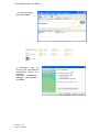
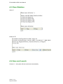
Set the parameters in
the “Name Servers”
label.
7. Click “OK”, complete the settings.
8. Double click the
“Internet Explorer”
icon on the desktop,
open the IE browser,
input a website, then
you can login the
web.
Version.: V1.0
Page 30 Total 95
EX-9162M51A SBC User Manual
2.5.1.2 Bluetooth Access
Please prepare the necessary hardware and software before the Bluetooth connection.
Table 2-4: Hardware Required for Bluetooth access
Requirement
Description
Bluetooth
Device
Such as a Bluetooth mobile phone, to activate the Bluetooth function.
Antenna
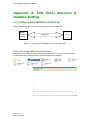
Use the standard Bluetooth antenna and connect it to the antenna
interface.
Figure 2-7 Shows How to Connect WiFi/Bluetooth Antenna.
Figure 2-7: Antenna Connection
Test Software
Table 2-5 lists the software required to run the test.
Table 2-5: Software Required for BT test
Requirement
bthbcsp.dll
Test Sequences
Version.: V1.0
Page 31 Total 95
Description
Driver .dll file of Bluetooth module, that is
supported within WinCE
EX-9162M51A SBC User Manual
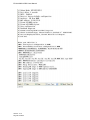
Please follow the guide to test the Bluetooth module step by step.
1. Turn on a Bluetooth device, such as a Bluetooth mobile.
2. Power on the EX-9162N51AB board.
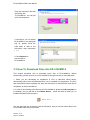
3.Open the WinCE OS directory “My Device\Control Panel\ Bluetooth Device
Properties”, and the “Bluetooth Manager”, a Dialog Box will pop up.
Version.: V1.0
Page 32 Total 95
EX-9162M51A SBC User Manual
4. Click the button “Scan Device”, then the Bluetooth module will scan other existing
Bluetooth device.
5. If the Bluetooth mobile is on, the module can scan it, and the name and address of the
Bluetooth device will be displayed in the dialog “Untrusted”.
Version.: V1.0
Page 33 Total 95
EX-9162M51A SBC User Manual
2.5.2 WiFi / Bluetooth API
The API fulfills the function of IP Configure, POWER ENABLE/DISABLE, WiFi and BT
switch.
2.5.2.1 Overview
The API provides the switch of WiFi and Bluetooth. WiFi or Bluetooth works at one
moment alternatively.
In order for power saving, please turn off the power of WiFi/Bluetooth Module when no
use.
2.5.2.2 API Function
Interface
1
BOOL WiFiBTPowerOn(int nModule)
2
BOOL WiFiBTPowerOff(int nModule)
2.5.2.3 API Function Description
1. CEX-9162M51ACtl::WiFiBTPowerOn
Set module opened.
BOOL WiFiBTPowerOn(int nModule)
Parameters
nModule
[in] The specified module ID
1: WIFI
2: Bluetooth
Return value
Set successful return true, else false
2. CEX-9162M51ACtl::WiFiBTPowerOff
Set Module Close.
BOOL WiFiBTPowerOff(int nModule)
Parameters
nModule
[in] The specified module ID
1: WIFI
2: Bluetooth
Return value
Set successful return true, else false
2.5.2.4 Application Example
If set to open WIFI module, the code is as follows:
m_pDvcBase->WiFiBTPowerOn(1);
Version.: V1.0
Page 34 Total 95
EX-9162M51A SBC User Manual
If set to turn off WIFI modules, the code is as follows:
m_pDvcBase->WiFiBTPowerOff (1);
Version.: V1.0
Page 35 Total 95
EX-9162M51A SBC User Manual
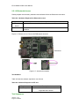
2.6 KeyPad Function
2.6.1 Introduction
The KPP (Keyboard Port) is a fixed key function as below.
Figure 2-8: Keypad Layout
2.6.2 Connector
KPP port can be found on Port B Connector.
2.6.3 Electrical Parameters
Table 2-6: Key Board Electrical Parameters
Parameter
High-level output voltage
Low-level output voltage
High-Level DC input voltage
Low-Level DC input voltage
Version.: V1.0
Page 36 Total 95
Sym Min Typ Max
VOH
VOL
VIH
VIL
2.9
2.2
0
3.1
-
3.3
0.15
3.3
0.45
Unit
V
V
V
V
EX-9162M51A SBC User Manual
2.7 LAN Function
2.7.1 Introduction
The Local Area Network (LAN) is a low-power 10BASE-T/100BASE-TX physical
layer(PHY) transceiver that transmits and receives information through unshielded
twisted-pair cable.
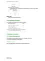
2.7.2 LAN Configure
Figure 2-9: LAN Connector
Please follow the steps to activate LAN.
WinCE6.0ÆStartÆSettingsÆNetwork and Dial-up Connections
Version.: V1.0
Page 37 Total 95
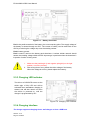
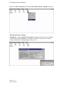
EX-9162M51A SBC User Manual
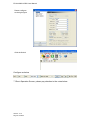
Right click “FEC1”ÆProperties, then dialog “FEC Ethernet driver” Settings will pop up.
“FEC Ethernet driver” Settings:
ÆIP Address Æ Select “Specify an IP address”, please fill in the number of IP address,
subnet mask and default gateway, for example, IP address: 192.168.1.58 Æ subnet
mask: 255.255.255.0 Æ default gateway: 192.168.1.1.
Version.: V1.0
Page 38 Total 95
EX-9162M51A SBC User Manual
Then configure Name Servers, for instance, set Primary DNS as 192.168.1.1.
At last, click OK, and you can browse explorer.
Version.: V1.0
Page 39 Total 95
EX-9162M51A SBC User Manual
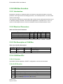
2.8 SD Card Function
The Secure Digital Card (SD) is an evolution of MMC technology. It is specifically
designed to meet the security, capacity, performance, and environment requirements
inherent in newly emerging audio and video consumer electronic EX-9162M51As.
2.8.1 Connector
Figure 2-10: SD Card Connector
2.8.2 SD card identify
The time for SD card identifying is various, depends on the SD card capacity. So far, the
max capacity ever tested is 32GB.
Version.: V1.0
Page 40 Total 95
EX-9162M51A SBC User Manual
2.9 LCD Display Function
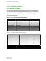
2.9.1 Approved LCD panel
The following LCD panels have been tested and approved for the EX-9162M51A board.
Please refer to the following specifications to determine which model to incorporate into
your application.
Many LCD module could match EX-9162M51A, but LCD change needs to modify LCD
device driver and backlight power, because there is no standard LCD interface in LCD
field. We provide some converter boards for different LCD panels, such as 7” TFT, 7”
LVDS, and VGA Monitors, etc.
Table 2-7:
3.5’’ LCD general specification (Example)
Model
Screen Size
Display Resolution
AM-320240LATNQW-T00H
3.5 inch (diagonal)
320(W)*240(H)
dot
Active Area
70.08 x 52.56
mm
Dot pitch
0.073(W)*0.219(H)
mm
Color configuration
Overall Dimension
Input Interface
Power Consumption
Power
R.G.B-stripe
77.8(W)x66.0(H)x5.5(T)
Digital 18-bits RGB
185mA in all black
3.0~3.6
Table 2.8
Unit
mm
V
7” LCD general specification (Example)
Model
Screen Size
Display Resolution
Active Area
Pixel pitch
Color configuration
Overall Dimension
Backlight unit
Display color
Power Consumption
Power Supply for LCD
Power Supply Current For LCD
Power Supply for LED
Power Supply Current For LED
Version.: V1.0
Page 41 Total 95
AM-800480E3TMQW-T01H-A
7 inch(diagonal)
800RGB(W)* 480(H)
152.4(W)*91.44 (H)
0.195(W)*0.1905(H)
R.G.B Vertical stripe
165(W)*104(H)*7.06 (D)
LED
262,144
185mA in all black
3.0~4.0
200~300
9.3~9.9
180
Unit
dots
mm
mm
mm
colors
V
mA
V
mA
EX-9162M51A SBC User Manual
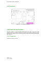
2.9.2 Connector
Figure 2-11 : LCD Display Connector
2.10 Touch Screen Function
The touch screen is a 12-bit successive approximation ADC with a synchronous serial
interface and low on resistance switches for driving touch screens. The touch screen
operates from a single 2.2V to 5.25V power supply and features throughput rates greater
than 125kSPS.
2.10.1 Connector
Available on Display connector
Version.: V1.0
Page 42 Total 95
EX-9162M51A SBC User Manual
2.11 USB Host Function
The Universal Serial Bus Host (USB H) is fully compliant with Universal Serial Bus
Specification Rev. 2.0. The USB H can transmit and receive USB data at high-speed (480
Mbit/s), full-speed (12 Mbit/s) or low-speed (1.5 Mbit/s).
Table 2-9: USB Host Pin Description
Pin Name
Symbol Function
DM
DP
I/O
I/O
data minus (D-) pin of the USB cable
data plus (D+) pin of the USB cable
2.11.1 Connector
Available on PORT A Connector.
Version.: V1.0
Page 43 Total 95
EX-9162M51A SBC User Manual
2.12 USB OTG Function
2.12.1 Overview
The Universal Serial Bus On-The-Go (USB OTG) allows two USB EX-9162M51As to talk
to each other without requiring the services of a personal computer (PC). Although OTG
appears to add peer-to-peer connections to the USB world, it does not. Instead, USB OTG
retains the standard USB host/peripheral model, in which a single host talks to USB
peripherals. OTG does introduce, however, the dual-role EX-9162M51A, or simply stated,
a EX-9162M51A capable of functioning as host or peripheral. Part of the magic of OTG is
that a host and peripheral can exchange roles if necessary.
2.12.2 USB OTG Pin definition
Table 2-10: USB OTG Pin Description
Pin Name Sym
Function
1
2
3
4
5
Power pin of the USB cable. Vbus = 5V
Data minus (D-) pin of the USB cable
Data plus (D+) pin of the USB cable
Identification (ID) pin of the mini-USB cable.
Ground
Vbus
DM
DP
ID
GND
I/O
I/O
I/O
I
GND
2.12.3 Connector
Figure 2-12: USB OTG connector Location
Version.: V1.0
Page 44 Total 95
EX-9162M51A SBC User Manual
2.13 Serial Port Function
2.13.1 Overview
The Universal Asynchronous Receiver/Transmitter (UART) ports do compile with standard
RS232 specification.
The UART generates baud rates based on a dedicated input clock and its programmable
divisor. The UART also contains programmable auto baud detection circuitry to receive 1
or 2 stop bits as well as odd, even no parity. The receiver detects framing errors, idle
conditions, BREAK characters, parity errors, and overrun errors.
UART is COM port without any driver, IO voltage is 3.1V on EX-9162M51A. For some
application, directly drive hardware modules by UART 3.1V. You could also do this without
driver chip. Please remove out any driver chip and solder on the necessary resistor
networks to reach it.
2.13.2 Serial Port Connector
Available on PORT B connectors.
2.13.3 RS232 Pin Description
Table 2-11: RS232 Pin Description
Pin
Name
Sym
Function
2
3
5
7
8
RXD
TXD
SG
RTS
CTS
I
O
GND
I/O
I
Serial Data Input (RXD)
Serial Data Output (TXD)
Ground Signal
This line informs the Modem that the UART is ready to exchange data.
This line indicates that the Modem is ready to exchange data.
2.13.4 Port List
UART1 : iMX51 default for system console, debug port ; RS232 driver chip
UART2 : Optional, available only in case of no Bluetooth,
UART3 : On extension port B, 3.15V signal, without RS232 driver.
Table 2-12 : UART Port List
No.
Functions
COM1
RS232
COM2
COM3
RS232
3.15V UART
Version.: V1.0
Page 45 Total 95
WinCE COM
COM port1
COM port2
COM port3
Connectors
System console, debug port
Optional, this port shares with Bluetooth
Without RS232 driver chip
On extension Port B J6, pin 5/pin 6
EX-9162M51A SBC User Manual
2.13.5 Electrical Parameters
Table 2-13 : UART Electrical Parameters
Parameter
Sym Min Typ Max Units
High-level output voltage
Low-level output voltage
High-Level DC input voltage
Low-Level DC input voltage
VOH
VOL
VIH
VIL
2.9
2.2
0
3.1
-
3.3
0.15
3.3
0.45
V
V
V
V
Table 2-14: RS232 Electrical Parameters
Parameter
Condition
Min
Typ
3K ohm load to ground at all
driver output.
±5.0
±5.4
Max
Units
Driver Outputs
Output Voltage Swing
Output Resistance
Output Short-Circuit Current
Receiver Input
Input Voltage Range
Input Threshold LOW
Input Threshold HIGH
Input Hysteresis
Input Resistance
Version.: V1.0
Page 46 Total 95
V
300
VOUT=0V
VOUT=±15V
ohm
±35
±70
-15
0.6
3
±60
±100
+15
1.2
1.5
0.3
5
2.4
7
mA
V
V
V
V
Kohm
EX-9162M51A SBC User Manual
2.14 GPIO Function
2.14.1 Overview
GPIO configuration and access to input and output pin of the state, including configurable
GPIO pin: xIO8-xIO15、xIO4、xIO5.
2.14.2 API Functions
Interface
1
BOOL sDIO_SetConfig(DIO16 nPortConfig)
2
BOOL sDIO_GetConfig(DIO16& nPortConfig)
3
BOOL sSetDOState(DIO16 nPortOut)
4
BOOL sGetDIState(DIO16& nPortIn)
2.14.3 API Function Description
1. CEX-9162M51ACtl::sDIO_SetConfig
Configure GPIO input, output.
BOOL sDIO_SetConfig(DIO16 nPortConfig)
Parameters
nPortConfig
[in] Contains 10 GPIO definition of pin, 0 is output, 1 is the input, the definition file
reference Public.h.
Return value
Set successful return true, else false.
2. CEX-9162M51ACtl::sDIO_GetConfig
Get GPIO input and output status.
BOOL sDIO_GetConfig(DIO16& nPortConfig)
Parameters
nPortConfig
[out] Contains 10 GPIO definition of pin, 0 is output, 1 is the input.
Return value
Get successful return true, else false.
3. CEX-9162M51ACtl::sSetDOState
Set the state of the output pin.
BOOL sSetDOState(DIO16 nPortOut)
Parameters
nPortOut
[in] Set the level of change on the output pin, 0 is low, 1 is high.
Return value
Set successful return true, else false.
Version.: V1.0
Page 47 Total 95
EX-9162M51A SBC User Manual
4. CEX-9162M51ACtl::sGetDIState
To obtain input on the level of change in pin.
BOOL sGetDIState(DIO16& nPortIn)
Parameters
nPortOut
[out] 0 is low, 1 is high.
Return value
Get successful return true, else false.
2.14.4 An Example to Call APIs
For example, xIO4, xIO8 configured as output, the others for the input pin, the code is as
follows:
DIO16
aDIO1;
aDIO1.nDIO |= 0x1;
aDIO1.nDIO |= 0x4;
m_pDvcBase->sDIO_SetConfig(aDIO1);
Now, configure the Output pin of xIO4, xIO8 state, xIO4 high, xIO8 low, the code is as
follows:
DIO16
aDIO1;
aDIO1.nDIO = 0x0;
aDIO1.nDIO |= 0x1;
m_pDvcBase->sSetDOState(aDIO1);
To obtain the state of the input pin, just look at the corresponding position, it is 0 or 1 on
the input pin, the code is as follows:
DIO16
aDIO1;
aDIO1.nDIO = 0x0;
m_pDvcBase->sGetDIState(aDIO1);
Version.: V1.0
Page 48 Total 95
EX-9162M51A SBC User Manual
2.15 ADC Function
2.15.1 API Overview
The ADC API is to read ADC value provided, and set the upper and lower warning-level
value.
You could set the maximum and minimum warning level for each ADC, and it will generate
interruption once the measured value is beyond maximum or minimum warning level.
2.15.2 API Function
Interface
1
BOOL SetAINConfig(AIOCONFIG aAIOConfig)
2
BOOL GetAINConfig(AIOCONFIG& aAIOConfig)
3
BOOL sGetAINState(AIOADC& nAIOIn)
4
BOOL ADCGetSingleChannelEightSamples(WORD channels,WORD* pADCOut)
2.15.3 API Function Description
1. CEX-9162M51ACtl::SetAINConfig
Configure ADC values of the parameters, scan time, the upper and lower limits.
BOOL SetAINConfig(AIOCONFIG aAIOConfig)
Parameters
aAIOConfig
[in] Can be configured to scan time, the upper and lower limits, the definition file
reference Public.h.
Return value
Set successful return true, else false.
2. CEX-9162M51ACtl::GetAINConfig
Configuration parameter values for ADC.
BOOL GetAINConfig(AIOCONFIG& aAIOConfig)
Parameters
aAIOConfig
[out] ADC for the current scan time, and the upper and lower limit values
Return value
Get successful return true, else false.
3. CEX-9162M51ACtl::sGetAINState
Get the current value of ADC scan.
BOOL sGetAINState(AIOADC& nAIOIn)
Parameters
nAIOIn
[out] Six 16-bit ADC sampling value, the definition file reference Public.h.
Return value
Version.: V1.0
Page 49 Total 95
EX-9162M51A SBC User Manual
Get successful return true, else false.
4. CEX-9162M51ACtl::ADCGetSingleChannelEightSamples
Read the eight single-channel sampling value.
BOOL ADCGetSingleChannelEightSamples(WORD channels,WORD* pADCOut)
Parameters
channels
[in] Select channel number, range 5-7.
pADCOut
[out] ADC sampling point to read the value of the buffer for eight 16-bit integer value.
Return value
Get successful return true, else false.
2.15.4 An Example to Call APIs
For example, configure the ADC scan time is 10ms, maximum 40, minimum is 20, the
code is as follows:
AIOCONFIG aAIOConfig;
aAIOConfig.cSampleTime = 10;
aAIOConfig.nHighLimit = 40;
aAIOConfig.nLowLimit = 20;
m_pDvcBase->SetAINConfig(aAIOConfig);
Get an external voltage of 6 ADC sample value, the code is exemplified as follows:
AIOADC aAI;
m_pDvcBase->sGetAINState(aAI);
ADC Channel 6 for the eight sample values, code as follows:
WORD
nEightSample[8] = {0};
m_pDvcBase->ADCGetSingleChannelEightSamples(6,nEightSample);
Version.: V1.0
Page 50 Total 95
EX-9162M51A SBC User Manual
2.16 SPI Interface Function
2.16.1 Introduction
The Configurable Serial Peripheral Interface (CSPI) module allows rapid data
communication with less software interrupts than conventional serial communications.
Table 2-15: SPI Electrical Parameters
Pin(J5) Pin Name
Sym Function
19
CSPI1_MOSI
I/O
20
CSPI1_MISO
I/O
21
CSPI1_RDY
I
22
CSPI1_SCLK
I
24
CSPI1_SS
O
In Master mode, this bidirectional signal is a TX output
signal from the Data Shift register. In Slave mode, it is a RX
input from external SPI EX-9162M51A.
In Master mode, this bidirectional signal is a RX input signal
to the Data Shift register. In Slave mode, it is a TX output to
external SPI EX-9162M51A.
This signal triggers the CSPI to start a burst.
In Master mode, this bidirectional signal is a SPI clock
output. In Slave mode, it is a SPI clock input.
Peripherals Chip Select.
2.16.2 Electrical Parameters
Table 2-16: SPI Electrical Parameters
Parameter
High-level output voltage
Low-level output voltage
High-Level DC input voltage
Low-Level DC input voltage
Sym Min Typ Max Units
VOH
VOL
VIH
VIL
2.9
2.2
0
3.1
-
3.3
0.15
3.3
0.45
V
V
V
V
2.16.3 Connectors
Available on Port A.
2.16.4 SPI APIs
2.16.4.1 Overview
It provides multi-byte SPI read & write operation, which is derived from CCommunication
class.
2.16.4.2 Headers
File Type
Definition
Head file
Communication/ Communication.h
Communication/ SPI/ SPICom.h
Communication/ SPI/ ecspibus.h
Version.: V1.0
Page 51 Total 95
EX-9162M51A SBC User Manual
2.16.4.3 API Function
Interface
1
CSPICom(LPCWSTR strSPIName,int nChannel)
2
BOOL Open()
3
BOOL Close()
4
BOOL HasOpened()
5
DWORD Read(BYTE* pData,DWORD nLen,DWORD& nOPLen)
6
DWORD Write(BYTE* pData,DWORD nLen,DWORD& nOPLen)
2.16.4.4 API Function Description
1. CSPICom::CSPICom
Create an SPI device interface, is the constructor.
CSPICom(LPCWSTR strSPIName,int nChannel)
Parameters
strSPIName
[in] Specify the interface name.
nChannel
[in] Channel number.
Return value
Create successful return true, else false.
2. CSPICom::Open
Open the Device Communication port.
BOOL Open()
Parameters
NONE
Return value
Set successful return true, else false.
3. CSPICom::Close
Close Communication Ports.
BOOL Close()
Parameters
NONE
Return value
Set successful return true, else false.
4. CSPICom::HasOpened
Whether the Communication ports are opened.
BOOL HasOpened()
Parameters
NONE
Return value
Set successful return true, else false.
Version.: V1.0
Page 52 Total 95
EX-9162M51A SBC User Manual
5. CSPICom::Read
Data port reception facilities.
DWORD Read(BYTE* pData,DWORD nLen,DWORD& nOPLen)
Parameters
pData
[out] Point to the receiver buffer
nLen
[in] The length of receive data
nOPLen
[out] Undefined
Return value
Set successful return true, else false.
6. CSPICom::Write
Write data to the device port.
DWORD Write(BYTE* pData,DWORD nLen,DWORD& nOPLen)
Parameters
pData
[in] Point to send buffer
nLen
[in] Send data bytes
nOPLen
[out] Undefined
Return value
Set successful return true, else false.
2.16.4.5 An Example to Call API
#include "lib\Communication\SPI\SPICom.h"
To create an SPI device interface, the code is exemplified as follows:
CSPICom *m_pSPICom = NULL;
m_pSPICom = new CSPICom(TEXT("SPI1:"),0);
Open the port, the code is as follows:
if(m_pSPICom->HasOpened() == FALSE)
{
m_pSPICom->Open();
}
To read data to the device, the code is exemplified as follows:
DWORD nLength = 0;
BYTE cText[64] = {0};
m_pSPICom->Read(cText,2,nLength);
Write data to the device, the code is as follows:
Version.: V1.0
Page 53 Total 95
EX-9162M51A SBC User Manual
DWORD nLength = 0;
BYTE cText[64] =
"abcd";
int nL = strlen(cText);
m_pSPICom->Write(cText,nL,nLength);
Version.: V1.0
Page 54 Total 95
EX-9162M51A SBC User Manual
2.17 I2C Interface Function
2.17.1 Introduction
The Inter-Integrated Circuit (I2C) is a two-wire, bidirectional serial bus. This bus is suitable
for applications requiring occasional communications over a short distance between many
EX-9162M51As. The flexible I2C allows additional EX-9162M51As to be connected to the
bus for expansion and system development. The I2C operates up to 400kbps but it
depends on the pad loading and timing.
2.17.2 I2C Pin Description
Table 2-17: I2C Pin Description
Pin(J6)
Pin Name
Sym
Description
43
I2C1_CLK
O
I2C, serial clock output
44
I2C1_DAT
I/O
I2C, serial data input/output
2.17.3 I2C Connectors
Available on Port B connector.
2.17.4 I2C APIs
2.17.4.1 Overview
It provides multi-byte read and write I2C operation, which derived from CCommunication
class.
2.17.4.2 Headers
File Type
Definition
Head file
Communication/ Communication.h
Communication/ I2C/ I2CCom.h
Communication/ I2C/ i2cbus.h
2.17.4.3 API Function
Interface
1
CI2CCom(LPCWSTR strI2CName,BYTE byAddr)
2
BOOL Open()
3
BOOL Close()
4
BOOL HasOpened()
5
DWORD Read(BYTE* pData,DWORD nLen,DWORD& nOPLen)
6
DWORD Write(BYTE* pData,DWORD nLen,DWORD& nOPLen)
Version.: V1.0
Page 55 Total 95
EX-9162M51A SBC User Manual
2.17.4.4 API Function Description
1. CI2CCom::CI2CCom
Create an I2C device interface, is the constructor.
CI2CCom(LPCWSTR strI2CName,BYTE byAddr)
Parameters
strI2CName
[in] Specify the interface name.
byAddr
[in] Specified device address.
Return value
Create successful return true, else false.
2. CI2CCom::Open
Open the Device Communication port.
BOOL Open()
Parameters
NONE
Return value
Set successful return true, else false.
3. CI2CCom::Close
Close Communication Ports.
BOOL Close()
Parameters
NONE
Return value
Set successful return true, else false.
4. CI2CCom::HasOpened
Whether the Communication ports are opened.
BOOL HasOpened()
Parameters
NONE
Return value
Set successful return true, else false.
5. CI2CCom::Read
Data port reception facilities.
DWORD Read(BYTE* pData,DWORD nLen,DWORD& nOPLen)
Parameters
pData
[out] Point to the receiver buffer
nLen
[in] The length of receive data
Version.: V1.0
Page 56 Total 95
EX-9162M51A SBC User Manual
nOPLen
[out] Undefined
Return value
Set successful return true, else false.
6. CI2CCom::Write
Write data to the device port.
DWORD Write(BYTE* pData,DWORD nLen,DWORD& nOPLen)
Parameters
pData
[in] Point to send buffer
nLen
[in] Send data bytes
nOPLen
[out] Undefined
Return value
Set successful return true, else false.
2.17.4.5 An Example to Call APIs
#include "lib\Communication\I2C\I2CCom.h"
Create an I2C device interface, the code is as follows:
CI2CCom *m_pI2CCom = NULL;
m_pI2CCom = new CI2CCom(_T("I2C1:"),0x01);
Open the port, the code is as follows:
if(m_pI2CCom->HasOpened() == FALSE)
{
m_pI2CCom->Open();
}
Read the device registers in the data, the code is as follows: (This case of operation for
the 16 register.)
BYTE Registers[5] = {0};
DWORD nLen = 0;
Registers[0] = 0;
// Register Address
Registers[1] = 0x02; // Register Address
if(m_pI2CCom->Write(Registers,2,nLen)==FALSE)
return FALSE;
Sleep(20);
if(m_pI2CCom->Read(Registers,2,nLen)==FALSE)
return FALSE;
Write data to the device registers, the code is as follows:
Registers[0] = 0;
// Register Address
Version.: V1.0
Page 57 Total 95
EX-9162M51A SBC User Manual
Registers[1] = 0x02; // Register Address
Registers[2] = 0x1;
Registers[3] = 0x2;
if(m_pSGTLI2CCom->Write(Registers, 4,nLen) == FALSE)
return FALSE;
Version.: V1.0
Page 58 Total 95
EX-9162M51A SBC User Manual
2.17.5 HSI2C APIs
2.17.5.1 Overview
HSI2C APIs provide multi-byte read and write HSI2C operation, which is derived from
CCommunication class.
2.17.5.2 Headers
File Type
Definition
Head file
Communication/ Communication.h
Communication/ HSI2C/ HSI2CCom.h
Communication/ HSI2C/ hsi2cbus.h
2.17.5.3 API Function
Interface
1
HSI2CCom(LPCWSTR strI2CName,BYTE byAddr)
2
BOOL Open()
3
BOOL Close()
4
BOOL HasOpened()
5
DWORD Read(BYTE* pData,DWORD nLen,DWORD& nOPLen)
6
DWORD Write(BYTE* pData,DWORD nLen,DWORD& nOPLen)
2.17.5.4 API Function Description
1. HSI2CCom::HSI2CCom
Create an HSI2C device interface, is the constructor.
HSI2CCom(LPCWSTR strI2CName,BYTE byAddr)
Parameters
strI2CName
[in] Specify the interface name.
byAddr
[in] Specified device address.
Return value
Create successful return true, else false.
2. HSI2CCom::Open
Open the Device Communication port.
BOOL Open()
Parameters
NONE
Return value
Set successful return true, else false.
3. HSI2CCom::Close
Version.: V1.0
Page 59 Total 95
EX-9162M51A SBC User Manual
Close Communication Ports.
BOOL Close()
Parameters
NONE
Return value
Set successful return true, else false.
4. HSI2CCom::HasOpened
Whether the Communication ports are opened.
BOOL HasOpened()
Parameters
NONE
Return value
Set successful return true, else false.
5. HSI2CCom::Read
Data port reception facilities.
DWORD Read(BYTE* pData,DWORD nLen,DWORD& nOPLen)
Parameters
pData
[out] Point to the receiver buffer
nLen
[in] The length of receive data
nOPLen
[out] Undefined
Return value
Set successful return true, else false.
6. HSI2CCom::Write
Write data to the device port.
DWORD Write(BYTE* pData,DWORD nLen,DWORD& nOPLen)
Parameters
pData
[in] Point to send buffer
nLen
[in] Send data bytes
nOPLen
[out] Undefined
Return value
Set successful return true, else false.
2.17.5.5 Application Example
Note: Be sure to include in the source file
#include "lib\Communication\HSI2C\HSI2CCom.h"
Version.: V1.0
Page 60 Total 95
EX-9162M51A SBC User Manual
Create an HSI2C device interface, the code is as follows:
HSI2CCom *m_pHSI2CCom = NULL;
m_pHSI2CCom = new HSI2CCom(HSI2C1_FID,0x01);
Open the port, the code is as follows:
if(m_pHSI2CCom ->HasOpened() == FALSE)
{
m_pHSI2CCom ->Open();
}
Read the device registers in the data, the code is as follows: (This case of operation for
the 8 register.)
BYTE Registers[5] = {0};
DWORD nLen = 0;
Registers[0] = 0x02; // Register Address
if(m_pHSI2CCom->Write(Registers,1,nLen)==FALSE)
return FALSE;
//delay
Sleep(20);
if(m_pHSI2CCom->Read(Registers,1,nLen)==FALSE)
return FALSE;
Write data to the device registers, the code is as follows:
Registers[0] = 0x02; // Register Address
Registers[1] = 0x1; //Data
if(m_pHSI2CCom->Write(Registers, 2,nLen) == FALSE)
return FALSE;
Version.: V1.0
Page 61 Total 95
EX-9162M51A SBC User Manual
2.18 CAN Bus Function
2.18.1 Introduction
Designed for operation in especially-harsh environments, these devices feature cross-wire
protection, loss-of-ground and overvoltage protection, over-heated protection, as well as wide
common-mode range.
The transceiver interfaces the single-ended CAN controller with the differential CAN bus found
in industrial, building automation, and automotive applications. It operates over a –2V to 7V
common-mode range on the bus, and it can withstand common-mode transients of 25 V.
2.18.2 Electrical Parameters
Table 2-18: Electrical Parameters
Parameter
High-level output voltage
Low-level output voltage
High-Level DC input voltage
Low-Level DC input voltage
Sym
Min
Typ
Max
Unit
VOH
VOL
VIH
VIL
3.0
2.2
0
3.15
-
3.45
0.15
3.15
0.945
V
V
V
V
2.18.3 Pin Description of CAN Bus
Table 2-19: CAN Pin Description
Pin(J6)
Pin Name
Sym
Description
61
CAN-
O
Low bus output
62
CAN+
I/O
High bus output
2.18.4 CAN Bus APIs
2.18.4.1 Overview
It provides CAN bus operation, ON/OFF, configuration, receive and send data.
2.18.4.2 API Function
Interface
1
BOOL sCANOpen(void)
2
BOOL sCANClose(void)
3
BOOL sCAN_SetConfig(CANStructure aCANConfig)
4
BOOL sCAN_GetConfig(CANStructure& aCANConfig)
5
BOOL sCANSend(unsigned char* pBuf, int nLen)
6
BOOL sCANRead(unsigned char* pBuf, int nLen)
Version.: V1.0
Page 62 Total 95
EX-9162M51A SBC User Manual
2.18.4.3 API Function Description
1. CEX-9162M51ACtl::sCANOpen
Open CANBUS module.
BOOL sCANOpen(void)
Parameters
NONE
Return value
Set successful return true, else false.
2. CEX-9162M51ACtl::sCANClose
Close CANBUS module.
BOOL sCANClose(void)
Parameters
NONE
Return value
Set successful return true, else false.
3. CEX-9162M51ACtl::sCAN_SetConfig
Configure the parameters Canbus.
BOOL sCAN_SetConfig(CANStructure aCANConfig)
Parameters
aCANConfig
[in] See the definition of this structure Public.h file.
Return value
Set successful return true, else false.
4. CEX-9162M51ACtl::sCAN_GetConfig
The parameter values for Canbus.
BOOL sCAN_GetConfig(CANStructure& aCANConfig)
Parameters
aCANConfig
[in] See the definition of this structure Public.h file
Return value
Set successful return true, else false.
5. CEX-9162M51ACtl::sCANSend
Send data to other devices,To send 8 bytes as the basic unit of.
BOOL sCANSend(unsigned char* pBuf, int nLen)
Parameters
pBuf
[in] Send buffer to point CanTxMsg structure
nLen
[in] The length of send data
Return value
Send successful return true, else false.
Version.: V1.0
Page 63 Total 95
EX-9162M51A SBC User Manual
6. CEX-9162M51ACtl::sCANRead
Receiving data from other devices, Receive 8-byte as the basic unit.
BOOL sCANRead(unsigned char* pBuf, int nLen)
Parameters
pBuf
[out] Point CanRxMsg receive buffer structure
nLen
[out] The length of receive data
Return value
Receive successful return true, else false.
2.18.4.4 An Example to Call APIs
Open Canbus module, the code is as follows:
m_pDvcBase->sCANOpen()
Configure the parameter values, the code is as follows:
CANStructure m_aCanbus;
m_aCanbus.CellStruct.CAN_TTCM = 0;
m_aCanbus.CellStruct.CAN_ABOM = 0;
m_aCanbus.CellStruct.CAN_AWUM = 0;
m_aCanbus.CellStruct.CAN_NART = 0;
m_aCanbus.CellStruct.CAN_RFLM = 0;
m_aCanbus.CellStruct.CAN_TXFP = 0;
m_aCanbus.CellStruct.CAN_Mode = CAN_Mode_Normal;
m_aCanbus.CellStruct.CAN_SJW = CAN_SJW_1tq;
m_aCanbus.CellStruct.CAN_BS1 = CAN_BS1_6tq;
m_aCanbus.CellStruct.CAN_BS2 = CAN_BS2_5tq;
m_aCanbus.CellStruct.CAN_Prescaler = 2;
/* CAN filter init */
m_aCanbus.FilterStruct.CAN_FilterNumber=0;
m_aCanbus.FilterStruct.CAN_FilterMode=CAN_FilterMode_IdMask;
m_aCanbus.FilterStruct.CAN_FilterScale=CAN_FilterScale_32bit;
m_aCanbus.FilterStruct.CAN_FilterIdHigh=0x0000;
m_aCanbus.FilterStruct.CAN_FilterIdLow=0x0000;
m_aCanbus.FilterStruct.CAN_FilterMaskIdHigh=0x0000;
m_aCanbus.FilterStruct.CAN_FilterMaskIdLow=0x0000;
m_aCanbus.FilterStruct.CAN_FilterFIFOAssignment=0;
m_aCanbus.FilterStruct.CAN_FilterActivation=1;
m_pDvcBase->sCAN_SetConfig(m_aCanbus);
Send data to other devices, the code is as follows:
BYTE cText[8] = “abcdefg”;
Int nL = Strlen(cText);
CanTxMsg
aTxMsg;
Version.: V1.0
Page 64 Total 95
EX-9162M51A SBC User Manual
aTxMsg.StdId = 1;
aTxMsg.ExtId = 2;
aTxMsg.RTR = CAN_RTR_DATA;
aTxMsg.IDE = CAN_ID_STD;
aTxMsg.DLC = 8;
memcpy(aTxMsg.Data, cText,nL);
m_pDvcBase->sCANSend((BYTE*)&aTxMsg,sizeof(CanTxMsg));
Receiving data from other devices, the code is as follows:
CanRxMsg
aRxMsg;
m_pDvcBase->sCANRead((BYTE*)&aRxMsg,sizeof(CanRxMsg));
Version.: V1.0
Page 65 Total 95
EX-9162M51A SBC User Manual
Chapter 3 Application Development
Guide
3.1 Application Development Architecture
PC
EX-9162M51A
SDK:
EX-9162M51A-SDKX
.X.msi
Development TOOL:
EVC
Connect :
ActiveSync
or
VS2005
EX-9162M51A
Mapping:
Figure 3-1: Application Development Architecture
3.2 How To Connect with PC
This section describes how to connect your EX-9162M51A to PC. Microsoft provides an
application tool for connection named ActiveSync.
3.2.1 Install the Software Tool Microsoft ActiveSync
ActiveSync is an application used for communication between EX-9162M51A and PC
under Windows CE, so the installation of ActiveSync on your PC is required.
Version.: V1.0
Page 66 Total 95
EX-9162M51A SBC User Manual
1. Obtain the tool Microsoft ActiveSync installation file. The version should be 3.8 or later.
You can download the newest version from the Microsoft Web Site:
(http://www.microsoft.com/downloads/browse.aspx?displaylang=en&productID=44C5
CD04-E8D3-4E3A-A3A5-31A4D151F304).
2. Install the Microsoft ActiveSync following the steps provided by the wizard. This
installation needs about 20MB disk space.
3.2.2 Run and Configure the Microsoft ActiveSync
This section describes how to configure the ActiveSync for connection.
1. Find and run the ActiveSync,
then the chart will appear.
2. Click File → Connection
settings
Version.: V1.0
Page 67 Total 95
EX-9162M51A SBC User Manual
3.
Select
“Allow
USB
connections” on the dialog
“Connection Settings” then
click OK (Figure 4-3)
Since EX-9162M51A does not support COM port connection with PC, please don’t select
“Allow connections to one of the following”
3.2.3 Connection
This section describes how to connect with PC.
1. Power on your EX-9162M51A. A few seconds later, you will see the WinCE 6.0 desktop
on the EX-9162M51A.
2. When the Windows CE 6.0 boot up, connect your PC to EX-9162M51A with a
standard-A plug & mini-B plug USB cable.
PC
M51
Standard-A plug
USB
mini-B
EX-9162
M51A
3. A few seconds later, the
ActiveSync on the EX-9162M51A
will send connection requirement
to PC, and the ActiveSync on
your PC will start connecting with
EX-9162M51A.
Version.: V1.0
Page 68 Total 95
EX-9162M51A SBC User Manual
4. The right figure will appear on
the connection.
Select Yes to set up a partnership
with EX-9162M51A then Click
Next.
5.Select Files
6. Click Finish.
Version.: V1.0
Page 69 Total 95
EX-9162M51A SBC User Manual
7. PC will synchronize
with EX-9162M51A
If ActiveSync does not
connect with EX-9162M51A
automatically, please do it
manually.
Select File → Connection
settings → click connect →
Click Next.
Version.: V1.0
Page 70 Total 95
EX-9162M51A SBC User Manual
Then the ActiveSync will start
connecting with
EX-9162M51A. You can get
voice from earphone.
If ActiveSync can not detect
EX-9162M51A, the dialog will
pop up, please check the
USB cable or refer to the
ActiveSync Help information
f h l
8. Click Explorer to
view the files in
EX-9162M51A
3.3 How To Download Files into EX-9162M51A
This chapter describes how to download users’ files to EX-9162M51A. Before
downloading, please connect PC to EX-9162M51A through ActiveSync with USB cable.
1. When you are developing an application in EVC or Microsoft Visual Studio,
downloading will be done automatically when you’ve compiled your application. The EVC
and Visual Studio finish compiling first, then use ActiveSync to download the result files of
compilation to the EX-9162M51A.
2. In case of downloading other files into the EX-9162M51A, please click My Computer in
PC desktop, and you will find an icon Mobile Device, which will show up when you ‘ve
installed the Microsoft ActiveSync).
You can also open the ActiveSync and click Explorer, and you will see all the files in the
EX-9162M51A like the picture below.
Version.: V1.0
Page 71 Total 95
EX-9162M51A SBC User Manual
It is just like a folder of PC, copy and remove files like what you do in PC.
3.4 SDK Install / Uninstall
Before developing Windows CE 6.0 applications for EX-9162M51A, an installation of M51
SDK(M51-SDKXX.MSI) is required. It can guarantee that your program be executed
correctly in WinCE 6.0 OS. This is the standard Microsoft WinCE application development
SDK. Please refer to the corresponding Microsoft document for the related application
development.
3.4.1 Install SDK
The following steps will lead you to install the M51 SDK into your Windows OS source
code tree and the Microsoft® eMbedded VC++ or Microsoft Visual Studio 2005
development environment.
1. Install EVC or Visual Studio 2005 from the installation discs if you haven’t installed
neither of them. Also, you can obtain the EVC installation files from the Microsoft Web Site
(http://www.microsoft.com/downloads/details.aspx?familyid=1DACDB3D-50D1-41B2-A10
7-FA75AE960856&displaylang=en), it’s free of charge.
2. Obtain the SDK installation file, M51-SDKX.X.msi, from CD. This file provides the
resources for application development.
3. Open the msi file, follow the guides provided by the wizard to install. This
installation needs about 110MB disk space.
Now you can start to develop your own WinCE 6.0 applications for the EX-9162M51A.
3.4.2 Uninstall SDK
This section describes how to remove an installation of M51 SDK from your PC.
Remove the SDK step by step:
1. Make sure you are not using the SDK when you are using the EVC or Visual Studio
2005.
2. Right click the icon M51-SDKX.X.msi, then select Uninstall.
Version.: V1.0
Page 72 Total 95
EX-9162M51A SBC User Manual
3.5 APIs Summary
3.5.1 Overview
EX-9162M51A API modules cover WiFi, BT, Audio, CANBUS, DIO, Voltage, SPI, I2C,
HSI2C, Communication, and so on.
3.5.2 Headers
File Type
Definition
Head file
M51Base.h
EX-9162M51ACtl.h Public.h
Communication/ Communication.h
Communication/ SPI/ SPICom.h
Communication/ SPI/ ecspibus.h
Communication/ HSI2C/ HSI2CCom.h
Communication/ HSI2C/ hsi2cbus.h
Communication/ I2C/ I2CCom.h
Communication/ I2C/ i2cbus.h
Library file
M51SeriesAPI.lib
Example
M51Test.exe
M51SeriesAPI.dll
3.5.3 API Member
BOOL GetLibraryVersion(char *pVer)
CEX-9162M51ACtl* Create(BYTE& nErrcode)
init
BOOL HasOpened(void)
BOOL Open(void)
BOOL Close(void)
WIFI/BlueTooth
BOOL WiFiBTPowerOn(int nModule)
BOOL WiFiBTPowerOff(int nModule)
BOOL SetAudioIn(int channelIn)
Audio
BOOL SetSpeakerCh(int channelOut)
BOOL SetAudioVolume(int nLVol,int nRVol)
BOOL GetAudioVolume(int& nLVol,int& nRVol)
BOOL sCANOpen(void)
BOOL sCANClose(void)
CANBUS
BOOL sCAN_SetConfig(CANStructure aCANConfig)
BOOL sCAN_GetConfig(CANStructure& aCANConfig)
BOOL sCANSend(unsigned char* pBuf, int nLen)
BOOL sCANRead(unsigned char* pBuf, int nLen)
BOOL sDIO_SetConfig(DIO16 nPortConfig)
BOOL sDIO_GetConfig(DIO16& nPortConfig)
BOOL sSetDOState(DIO16 nPortOut)
BOOL sGetDIState(DIO16& nPortIn)
BOOL sGetAINState(AIOADC& nAIOIn)
Version.: V1.0
Page 73 Total 95
EX-9162M51A SBC User Manual
BOOL SetAINConfig(AIOCONFIG aAIOConfig)
BOOL GetAINConfig(AIOCONFIG& aAIOConfig)
BOOL ADCGetSingleChannelEightSamples(WORD channels,
WORD* pADCOut)
Voltage
BOOL SetVoltage(REGULATOR_VREG regulator,
REGULATOR_VREG_VOLTAGE voltage)
BOOL GetVoltage(REGULATOR_VREG regulator,
REGULATOR_VREG_VOLTAGE* voltage)
BOOL HasOpened(void)
Communication
(HSI2C)
BOOL Open(void)
BOOL Close(void)
DWORD Read(BYTE* byDataAry, DWORD nLen,DWORD& nOPLen)
DWORD Write(BYTE* byDataAry, DWORD nLen,DWORD& nOPLen)
3.5.4 API Description
1. CM51Base::GetLibraryVersion
Get the software version number
BOOL GetLibraryVersion(char *pVer);
Parameters
pVer
Point to obtain the version number;
Return value
TRUE if return the version number, else NULL.
2. CEX-9162M51ACtl:: Create
Create EX-9162M51A object
CEX-9162M51ACtl* Create(pNotifyFun notifyFun,BYTE& nErrcode);
Parameters
notifyFun
Point to a callback function pointer. Define a global function, passing the function
name can be.
This callback function is used to pass the latitude and longitude GPS module
receives data, it declared:
typedef void (*pNotifyFun)(char* pData,int nType);
pData: Transmission of data content
nType: Transfer data length
nErrcode
Specifies the create error code.
Error code define list:
#define CREATE_OK
0
#define PARAM_INVALID
1
#define MEM_LACK
2
#define NOT_FIND_DLL
3
Return value
`
Version.: V1.0
Page 74 Total 95
EX-9162M51A SBC User Manual
TRUE if return a points to a EX-9162M51A object, else NULL.
3. CM51Base:: HasOpened
EX-9162M51A Communication ports are open
BOOL HasOpened(void);
Parameters
NONE
Return value
Return TRUE for all ports are open, FALSE have the port is not enabled.
4. CM51Base:: Open
Open EX-9162M51A on the Communication Port
BOOL Open(void);
Parameters
NONE
Return value
Return TRUE open all ports, FALSE have the port is not open.
5. CM51Base:: Close
Close EX-9162M51A on the Communication Port
BOOL Close(void);
Parameters
NONE
Return value
Return TRUE success, else failure.
3.5.5 An Example to call APIs in C/C++
Below is an example to create works and initialization steps under EVC.
1. create a new dialog-based applications engineering, works
"EX-9162M51AExample".
“File”-“new”- choose Workspaces tab
Version.: V1.0
Page 75 Total 95
entitled
EX-9162M51A SBC User Manual
“File”-“new”- choose Projects tab
Version.: V1.0
Page 76 Total 95
EX-9162M51A SBC User Manual
click “Next” until accomplishment.
It will provide the lib folder copied to the project directory.
Click “Compile”, shown below.
Version.: V1.0
Page 77 Total 95
EX-9162M51A SBC User Manual
2. Add the following code into the file EX-9162M51AExampleDlg.h.
Add the following code into the file EX-9162M51AExampleDlg.cpp.
Defined as the callback function global function STCBNotifyFun.
Version.: V1.0
Page 78 Total 95
EX-9162M51A SBC User Manual
Now, the object of EX-9162M51A pointer has been created, instantiated as above, so you
can access the M51SeriesAPI.lib through this pointer, which provides the public
methods. More details, please refer to the file EX-9162M51ACtl.h.
Version.: V1.0
Page 79 Total 95
EX-9162M51A SBC User Manual
Appendix A: LCD Panel Selection &
Rotation Setting
A.1 Configure EX-9162M51A and Run Up
Please make the connection between peripherals and EX-9162M51A.
IMX51
EX-916
2M51A
Debug Port
PC
Figure A1: To connect EX-9162M51A to PC with debug port
Find and run the AccessPort.exe, double-click it.
*AccessPort is a COM port. When you use HyperTerminal on your PC, random codes or
no data output may appear, however, it will not appear in AccessPort.
Version.: V1.0
Page 80 Total 95
EX-9162M51A SBC User Manual
Please configure
as the right figure
Click the Switch
Configure as below
** Eboot Operation Screen, please pay attention to the notes below
Version.: V1.0
Page 81 Total 95
EX-9162M51A SBC User Manual
Version.: V1.0
Page 82 Total 95
EX-9162M51A SBC User Manual
Eboot screen lasts for only 3 sec, then it will proceed WinCE automatically.
Due to short waiting time, please operate it as quickly as you can.
Please refer to the above figure and pay attention to the below:
1. To move Mouse to icon “1”,
2. Power On EX-9162M51A. Please touch “Space Bar” on your
keyboard once Eboot Screen show up as icon “2”
Till icon “3” show up, you could do some selection, else try again
3. Input MAC address, the first digit MUST be even.
Caution!
Don’t select icon “5”, this will erase WinCE even
Eboot, and all will crash.
A.2 Panel Selection
Input ‘ P’. Attention: there is a ‘space’ before ‘P’.
There are 5 models of LCD panel for selection.
The default is ‘1’, you can
select the model number of
the panel you selected.
Version.: V1.0
Page 83 Total 95
EX-9162M51A SBC User Manual
A.3 Panel Rotation
Select ‘r’
Default is ‘0’
A.4 Save and Launch
Choose ‘L’,the system will save and launch automatically.
Version.: V1.0
Page 84 Total 95
EX-9162M51A SBC User Manual
Version.: V1.0
Page 85 Total 95
EX-9162M51A SBC User Manual
Appendix B: iMX51 image file(NK)
Download
B.1 Setup and Configure
Before that, we need some COM Tool to display some debug message, COM tool may be
AccessPort or HyperTerminal or others.
Please make the operation step by step.
1.Run up AccessPort. Please refer to A.1 Configure and Run for the guide if necessary.
2. Connect the peripherals to EX-9162M51A board. Please refer to 2.7.2 LAN Configure and
2.13 Serial Port for the guide if necessary.
PC
LAN
Debug Port
Version.: V1.0
Page 86 Total 95
iMX31
EX-916
2M51A
EX-9162M51A SBC User Manual
3. Power on and enter into the interface EBOOT SETTING.
Please refer to Appendix A: Boot Setting for more details
Version.: V1.0
Page 87 Total 95
EX-9162M51A SBC User Manual
Find out the installation document WinCE_bin_load.zip, then unzip it.
IP setting:
Set the IP address. Make sure the two have same IP addresses
Copy the newest NK to the same directory, and NK’s name must be ‘boot.bin’.
Version.: V1.0
Page 88 Total 95
EX-9162M51A SBC User Manual
B.2 Download NK
NK is an executable image file for EX-9162M51A. You could create it with Microsoft
Platform Builder.
Here we brief how to download NK into EX-9162M51A
Input ‘dy’
Double-click
WinCE_bin_load.bat
Version.: V1.0
Page 89 Total 95
EX-9162M51A SBC User Manual
AccessPort(*) output is below:
*AccessPort is a COM tool, you can also use HyperTerminal
Download is Completed.
Power on again, you
will launch the latest
WinCE
Version.: V1.0
Page 90 Total 95
EX-9162M51A SBC User Manual
Appendix C: EX-9162M51A IP Setting
Please follow the steps to set the IP address.
1. Open
2. IP setting
Select Keyboard
Version.: V1.0
Page 91 Total 95
EX-9162M51A SBC User Manual
Set the IP address
3. Login network
Version.: V1.0
Page 92 Total 95
EX-9162M51A SBC User Manual
Appendix D: Terminal Tool Setting
Please set the terminal tools step by step.
1. Open
2. Creating and
setting
Version.: V1.0
Page 93 Total 95
EX-9162M51A SBC User Manual
When setting is
completed,
a
window
will
pop out as the
right figure.
3. Close
You could double click to bring
in a Terminal on successful
creation.
Version.: V1.0
Page 94 Total 95