1
EX-9162M51A SBC User Manual
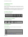
1.6 Extension Connectors
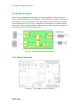
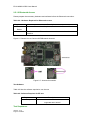
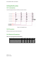
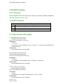
EX-9162M51A provides 2 extended connectors, Port A (J5) and Port B (J6), for the
function of I2C, SPI, GPIO, ADC, UART, USB, S-Video Signals, Key pad, and so on. The
function’s detailed description will be shown on Chapter 2. Port J7 is display port 1, and J4
is the mirror to J7 pins(left/right reversed) , placed on Top layer. J5,J6 and J7 are used to
plug with Carrier Board EX-9162X51AB directly.
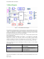
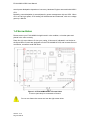
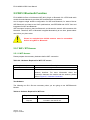
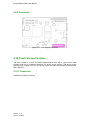
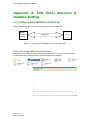
1.6.1 Connector Location Diagram
Figure1-4:Connector Location Diagram
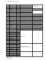
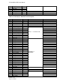
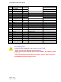
1.6.2 Pin Assignment
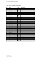
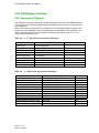
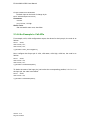
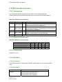
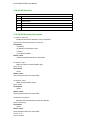
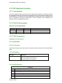
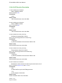
Table 1-1: Port A(J5)-Extension Pin Description
Pin
1
2
3
4
5
6
7
8
9
10
11
12
Name
USB HS DP
USB HS DM
5V
GND
RXD1
TXD1
RTS1
CTS1
RXD2
TXD2
RTS2
CTS2
Version.: V1.0
Page 10 Total 95
Sym
I/O
I/O
PO
GND
I
O
I
O
I
O
I
O
Port Function
Remark
USB Host
USB Host port
5V Power Output
Output from DC2DC
UART1, System Debug port
iMX51 UART port 1
UART2, Optional, provided only
when no Bluetooth
iMX51 UART port 2