1
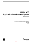
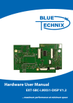
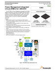
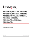
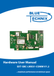
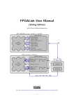
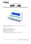
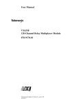
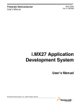
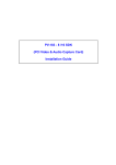
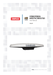
Hardware User Manual SBC-i.MX51 V1.2 Contact Bluetechnix Mechatronische Systeme GmbH Waidhausenstraße 3/19 A-1140 Vienna AUSTRIA/EUROPE [email protected] http://www.bluetechnix.com Document No.: 100-1440-1.2 Document Revision 1 Date: 2010-05-17 SBC-i.MX51 V1.2 Hardware User Manual 2 Table of Contents Table of Contents .................................................................................................................................................................................. 3 1 Overview ........................................................................................................................................................................................ 5 1.1 Features................................................................................................................................................................................. 5 1.2 Block Diagram ..................................................................................................................................................................... 6 2 Components ................................................................................................................................................................................. 7 2.1 Integrated Components .................................................................................................................................................. 7 2.2 Optional Components...................................................................................................................................................... 8 3 Standard I/O Connectors .......................................................................................................................................................... 9 4 Extension Connectors ............................................................................................................................................................. 11 4.1 GPIO/Automation Connector (X3) ............................................................................................................................ 11 4.2 Digital Video Connector (X11) .................................................................................................................................... 15 4.3 Audio Connector (X17) ................................................................................................................................................. 18 4.4 Reset / Power-On Connector (X16) ........................................................................................................................... 18 4.5 Power Supply Connector (X18) .................................................................................................................................. 18 5 Operating Conditions ............................................................................................................................................................. 19 5.1 Electrical Characteristics ............................................................................................................................................... 19 5.2 Digital I/O Characteristics............................................................................................................................................. 19 5.3 Analog Inputs ................................................................................................................................................................... 19 5.4 Boot Mode Settings........................................................................................................................................................ 20 6 Mechanical specification ....................................................................................................................................................... 21 6.1 Connector Locations...................................................................................................................................................... 21 6.2 Mounting Hole Dimensions ........................................................................................................................................ 22 7 Anomalies ................................................................................................................................................................................... 23 8 Product Changes ...................................................................................................................................................................... 24 9 Document Revision History .................................................................................................................................................. 25 10 List of Abbreviations ........................................................................................................................................................... 26 11 List of Figures and Tables .................................................................................................................................................. 27 SBC-i.MX51 V1.2 Hardware User Manual 3 Edition 2008-09 © Bluetechnix Mechatronische Systeme GmbH 2008 All Rights Reserved. The information herein is given to describe certain components and shall not be considered as a guarantee of characteristics. Terms of delivery and rights of technical change reserved. We hereby disclaim any warranties, including but not limited to warranties of non-infringement, regarding circuits, descriptions and charts stated herein. Bluetechnix makes and you receive no warranties or conditions, express, implied, statutory or in any communication with you. Bluetechnix specifically disclaims any implied warranty of merchantability or fitness for a particular purpose. Bluetechnix takes no liability for any damages and errors causing of the usage of this board. The user of this board is responsible by himself for the functionality of his application. He is allowed to use the board only if he has the qualification. More information is found in the General Terms and Conditions (AGB). Information For further information on technology, delivery terms and conditions and prices please contact Bluetechnix (http://www.bluetechnix.com). Warning Due to technical requirements components may contain dangerous substances. The Core Modules and development systems contain ESD (electrostatic discharge) sensitive devices. Electro-static charges readily accumulate on the human body and equipment and can discharge without detection. Permanent damage may occur on devices subjected to high-energy discharges. Proper ESD precautions are recommended to avoid performance degradation or loss of functionality. Unused Core Modules and Development Boards should be stored in the protective shipping SBC-i.MX51 V1.2 Hardware User Manual 4 1 Overview 1.1 Features The Single Board Computer SBC-i.MX51 is based on Freescale’s high-performance i.MX51x mobile platform, incorporating an ARM Cortex A8 CPU, an Image Processing Unit (IPUv3EX) and a Video Processing Unit (VPU). The IPUv3EX provides comprehensive support for the connectivity to displays and cameras. The VPU supports hardware encoding and decoding of MPEG-4, H.263 and H.264 standards. Its memory capabilities (NAND Flash, DDR2 SDRAM) and numerous interfaces turn the SBC-i.MX51 into the ultimate development board for future high-end embedded devices comparable to netbooks. Other target applications include industrial automation and control systems. Figure 1-1 shows board’s the features. Figure 1-1: SBC-i.MX51 features SBC-i.MX51 V1.2 Hardware User Manual 5 1.2 Block Diagram Figure 1-2 shows the main components and connectors on the SBC-i.MX51. Figure 1-2: SBC-i.MX51 Overview SBC-i.MX51 V1.2 Hardware User Manual 6 2 Components The SBC-i.MX51 contains many peripherals to provide a lot of interfacing options. The next paragraphs give you a short overview of each component including a brief feature list. Please refer to the manufacturer’s user manuals for more details. 2.1 Integrated Components i.MX51 processor (Freescale, MCIMX515DJM8C) Multimedia processor for mobile and low power application. ARM Cortex A8 core 800 MHz core clock frequency 200 MHz DDR2 SDRAM interface Dynamic power management Hardware video codec Powerful graphics acceleration (OpenGL and OpenVG) i.MX Companion IC (Freescale, MC13892JVK) The Power Management IC MC13892 is Freescale’s companion IC for i.MX series CPUs. It generates all required power supplies, and contains some additional features: Dynamic power control system Battery charging control logic Octal 10-Bit ADC Single RGB LED driver Backlight LED driver Real Time Clock DDR2 SDRAM (Micron, MT47H64M16HR-25 IT) 512 MByte DDR2-800 (800MB/s) NAND Flash (Micron, MT29F16G08CBABAWP) 2GByte 8 Bit 4k pagesize Ethernet Physical Transceiver (Micrel, KSZ8041) Ethernet/IEEE 802.3 10BaseT 100BaseTX MII Interface SBC-i.MX51 V1.2 Hardware User Manual 7 USB Physical Transceiver (SMSC, USB3317) USB-IF “High-Speed” compliant (V2.0) ULPI interface USB HUB (SMSC, USB2514I) 4 port HUB USB-IF “High-Speed” compliant (V2.0) High Speed, Full-Speed and Low-Speed compatible USB to UART Bridge (SiLabs, CP2102) USB device Usable for terminal applications HDMI Transmitter (Analog Devices, AD9889B) HDMI 1.1 compatible I2S and SPDIF audio encoding Audio Codec (Freescale, SGTL5000) 2.2 Stereo Line In Stereo Line Out Mic In (Electret or Dynamic microphones supported) Optional Components A few components, are not mounted in the current version of the SBC-i.MX51. If you want to use these components contact Bluetechnix for custom assembling. These optional components are: 2.5W Stereo Audio Amp (National Semiconductors, 2x NCP2820) PCB Microphone (Knowles Acoustics, SPM0208HD5) 3-Axis Acceleration Sensor (Freescale, MMA7660FC) CVBS Connector SBC-i.MX51 V1.2 Hardware User Manual 8 3 Standard I/O Connectors There are two types of connectors on the SBC-i.MX51: standard I/O Connectors and Extension Connectors. All standard I/O Connectors (except JTAG) are accessible on the front or rear side of the board (see Figure 3-1). Ethernet USB‐ OTG 4x USB Host USB Device HDMI JTAG SD‐card socket Audio Jacks Power Plug Figure 3-1: Standard Interface positions Front side Connectors: Triple Audio Jack (Mic-In, Line-In and Headset-Out) TV out (not populated on SBC-i.MX51 V1.2) SD-card socket Power plug Rear side Connectors: Ethernet 4x USB A (host connector) SBC-i.MX51 V1.2 Hardware User Manual 9 Mini USB AB (USB-OTG connector) USB-B (device connector for terminal application) HDMI Display output JTAG Connector: A standard ARM JTAG connector with 20 pins is available for debugging. LED and Push Buttons: There are two push buttons and a single RGB-LED for user interaction. The RGB LED is connected to the MC18392 LED interface. The push buttons have following functions: S1: RESET S3: Power On RGB‐LED PON RESET Figure 3-2: LED and button positions If the SBC is enclosed in a chassis, you can mount a light pipe (515-1011F from DIALIGHT) above the RGB-LED for guiding the light to a front side panel. SBC-i.MX51 V1.2 Hardware User Manual 10 4 Extension Connectors The Extension Connectors allow connecting additional hardware to the SBC-i.MX51. Bluetechnix offers additional hardware for the SBC-i.MX51 such as a display extension board. See our website for more information. (http://www.bluetechnix.com/goto/sbc-i.mx51) All connector I/O pins are either connected to the i.MX or to the MC13892 (see pin description). Most of the pins connected to the i.MX have alternate functions; for more details see the Pin Description Tables and consult the i.MX51 datasheet. The connectors for the GPIO- and Video Extension Connectors are 5177983-2 from Tyco Electronics (mating part is 5179031-2). All other connectors are standard 2.54mm-pitch headers. Figure 4-1: Extension Connector positions 4.1 GPIO/Automation Connector (X3) The GPIO/Automation Extension Connector includes several serial interfaces, as well as a keypad, power-LED drivers and three analog inputs. See Figure 4-2 for a feature overview and Table 4-3 for a detailed pin description. SBC-i.MX51 V1.2 Hardware User Manual 11 Figure 4-2: GPIO/Automation Extension Connector Interfaces 4.1.1 One-Wire-Interface The 1-Wire interface is available to communicate with a generic 1-Wire device defined by Maxim-Dallas. 4.1.2 Analog-In Three 10-Bit analog-digital-converters (ADC) are available for general use. The inputs are connected to ADIN[5..7] on the MC13892 companion chip. 4.1.3 I2C The two I2C serial busses allow the attachment of a variety of peripheral components to the GPIO/Automation Connector. Note that the I2C1 is shared with the CSPI1 Serial Peripheral Interface. 4.1.4 Keypad The connector features keypad pins to connect a six-by-four button matrix keyboard to the specially designated interface of the i.MX51. 4.1.5 LEDs The MC13892 features an auxiliary display LED driver output and a keypad LED driver output. Yet, please refer to the Errata sheet of the MC13892 for problems which may appear when using this interface. Figure 4-3: LED connection circuit SBC-i.MX51 V1.2 Hardware User Manual 12 4.1.6 PWM Two PWM outputs are available on the GPIO/Automation Extension Connector. Please note that the PWM1 is also present on the Video Extension Connector. 4.1.7 SPI Two Serial Peripheral Interfaces are available on the connector. The CSPI1 interface is shared with the I2C1 and provides two slave select signals, the CSPI is shared with the SD-card interface, and provides only a single slave select signal. 4.1.8 SSI This interface can be used as alternate digital audio channel and is connected to the AUD4 interface of the i.MX51. 4.1.9 UART The signals of the UART2 and UART3 are available on the extension connector for the connection of a variety of peripheral devices. 4.1.10 Power Supplies The GPIO / Automation Extension Connector provides seven different supply voltages. They can be used on a custom extension board. Some supply voltages are generated by the MC13892 and can be set to different values. They must be set and enabled first, by configuring the companion IC. The following table shows the maximum supply current for each voltage domain. Signal Name P_5V0 P_VIOHI1) P_SW41) P_GEN21) P_AUDIO P_VIDEO P_SWLED2) Voltage 5.0V 2.775V 1.8V 3.15V 2.3V, 2.5V, 2.775V, 3.0V 2.5V, 2.6V, 2.7V, 2.775V 4.3V to 26.5V Maximum Supply Current 500mA3) 50mA3) 50mA3) 70mA 150mA 350mA 60mA Table 4-1: Maximum power consumption for the GPIO / Automation Connector supplies 1) It is not advisable to alter these voltages; otherwise the board may get damaged. The P_SWLED voltage drives the LEDs connected to the LED-driver pins. The output voltage will be set automatically by the MC13892. For LED connectivity see Figure 4-3. 3) Be aware that this power supply is available on both extension connectors and this is the maximum current that can be drawn altogether. 2) 4.1.11 I/O Power Domains All digital I/O pins are part of one of three power domains: P_SW4 (1.8V), P_VIOHI (2.775V) or P_GEN2 (3.15V). The following table shows each interface with the corresponding voltage level. Interface 1-Wire I2C2 Keypad Pins 1 2 10 Power Domain P_VIOHI P_VIOHI P_SW4 SBC-i.MX51 V1.2 Hardware User Manual Description OWIRE I2C1.SCL, I2C1.SDA KPP.COL[0..5], KPP.ROW[0..3] 13 Interface PWM SD SPI Pins 2 6 6 Power Domain P_VIOHI P_GEN2 P_SW4 SSI 6 P_VIOHI UART PON ADIN LED 4 1 3 2 P_VIOHI Open Drain P_SWLED Description PWM1, PWM2 SD2.CMD, SD2.CLK, SD2.D0, SD2.D1, SD2.D2, SD2.D3 CSPI1.MOSI, CSPI1.MISO, CSPI1.SS0, CSPI1.SS1, CSPI1.RDY, CSPI1.SCLK AUD4.RFS, AUD4.RSCK, AUD4.Tx, AUD4.Rx, AUD4.TSCK, AUD4.TFS UART2.TXD, UART2.RXD, UART3.TXD, UART3.RXD A_CTRL.PON1 – Power down Power Mgmt. ADC Input on MC13892 LED driver outputs Table 4-2: Power Domains for I/Os 4.1.12 Pin Description Table Pin No 1 2 3 4 5 6 7 8 9 10 11 12 13 14 15 16 17 18 19 20 21 22 23 24 25 26 27 28 29 30 31 32 33 34 35 36 37 38 Signal P_SWLED GND LED_AD A_CTRL_PON1 LED_KP GND GND EIM_D27 ADIN5 EIM_D24 ADIN6 GND ADIN7 OWIRE_LINE GND UART2_RXD P_GEN2 UART2_TXD SD2_CMD UART3_RXD SD2_CLK UART3_TXD SD2_D0 GND SD2_D1 GPIO1_2 SD2_D2 GPIO1_3 SD2_D3 GND GND P_SW4 CSPI1_MOSI KPP_ROW0 CSPI1_MISO KPP_ROW1 CSPI1_SS0 KPP_ROW2 Type PWR PWR O IpU O PWR PWR IO I IO I PWR I IO PWR I PWR O IO I O I IO PWR IO IO IO IO IO PWR PWR PWR IO I I I O I SBC-i.MX51 V1.2 Hardware User Manual Description Power Supply Power Ground LED driver output connected to MC18392 Power On Input LED driver output connected to MC18392 Power Ground Power Ground usable as I2C2_SCL or GPIO2_9 Analog input connected to MC18392 usable as I2C2_SDA or GPIO2_8 Analog input connected to MC18392 Power Ground Analog input connected to MC18392 One-wire interface Power Ground UART RxD or GPIO 1_20 Power Supply UART TxD or GPIO 1_21 SD-card interface or CSPI_MOSI UART RxD or GPIO 1_22 SD-card interface or CSPI_SCLK UART TxD or GPIO 1_23 SD-card interface Power Ground SD-card interface GPIO with PWM1 functionality SD-card interface GPIO with PWM2 functionality SD-card interface or CSPI_SS2 Power Ground Power Ground Power Supply SPI1 usable also as I2C1_SDA (default) or GPIO4_22 Keypad Row SPI1 usable also as GPIO4_23 Keypad Row SPI1 usable also as GPIO4_24 Keypad Row 14 39 40 41 42 43 44 45 46 47 48 49 50 51 52 53 54 55 56 57 58 59 60 CSPI1_SS1 KPP_ROW3 CSPI1_RDY KPP_COL0 CSPI1_SCLK KPP_COL1 AUD4_RFS KPP_COL2 AUD4_RSCK KPP_COL3 AUD4_TX KPP_COL4 AUD4_RX KPP_COL5 AUD4_TSCK P_VIDEO AUD4_TFS P_AUDIO GND P_5V0 GND P_5V0 O I I I IO I IO I IO I O I I I IO PWR IO PWR PWR PWR PWR PWR SPI1 usable also as GPIO4_25 Keypad Row SPI1 usable also as GPIO4_26 Keypad Column SPI1 usable as I2C1_SCL (default) or GPIO4_27 Keypad Column Audio Port 4 usable also as GPIO2_0 Keypad Column Audio Port 4 usable also as GPIO2_3 Keypad Column Audio Port 4 usable also as GPIO2_4 Keypad Column Audio Port 4 usable also as GPIO2_5 Keypad Column Audio Port 4 usable also as GPIO2_6 Power Supply Audio Port 4 usable also as GPIO2_7 Power Supply Power Ground Power Supply Power Ground Power Supply Table 4-3: GPIO / Automation Connector pin description 4.2 Digital Video Connector (X11) The Video Extension Connector is designed to add a custom video extension board with user-defined camera and display components, e.g. a CMOS sensor and a LCD display. Additionally, some GPIOs are available for configuring the interface and handshaking. Touchscreen functionality can be implemented by connecting four analog lines, which are routed to the MC13892, to an appropriate display. Figure 4-4: Digital Video Connector 4.2.1 Camera Sensor Interface Port (CSI1) A camera (e.g. an OmniVision OV2640 or OV2655) can be connected to the SBC-i.MX51x board using the CMOS Sensor Interface 1 (CSI1). SBC-i.MX51 V1.2 Hardware User Manual 15 Interface CSI1_Data CSI1_Control Pins 10 5 Power Domain P_SW4 P_SW4 I2C2 2 P_VIOHI Description CSI1.D0 - CSI1.D9 CSI1.VSYNC, CSI1.HSYNC, CSI1.PIXCLK, CSI1.MCLK, CSI1.PWDN I2C2.SDA, I2C2.SCL Table 4-4: CSI1 Interface description 4.2.2 LCD Port (DISP2) The DISP2 interface is available to connect an LCD display to the SBC-i.MX51 board. On the secondary display port, the i.MX51 supports resolutions up to 1280X768. Interface DISP2_Data DISP2_Control DISP2_Control PWM LED ADIN Pins 16 3 1 2 2 4 Power Domain P_VIOHI P_VIOHI P_SW4 P_VIOHI P_SWLED - Description DISP2.D0 – DISP2.D15 DISP2.VSYNC, DISP2.HSYNC, DISP2.CLK DISP2.DE PWM1, TFT.PWRCTRL - Contrast LED.MD - Display Backlight ADIN[1..4] – Touch screen Table 4-5: DISP2 Interface description 4.2.3 Power Supplies The Video Extension Connector provides six different supply voltages. They can be used for a custom extension board. Some supply voltages are generated by the MC13892 and can be set to different values. They must be set and enabled first, by configuring the companion IC. The following table shows the maximum supply current for each voltage. Signal Name P_5V0 P_SW41) P_GEN3 P_DIG P_CAM P_SWLED2) Voltage 5.0V 1.8V 1.8V, 2.9V 1.05V, 1.25V, 1.65V, 1.8V 2.5V, 2.6V, 2.75V, 3.0V 4.3V to 26.5V Maximum Current 500mA3) 50mA3) 50mA3) 50mA 250mA 60mA Table 4-6: Maximum power consumption for the Digital Video Connector supplies 1) It is not advisable to alter these voltages; otherwise the board may get damaged. The P_SWLED voltage drives the LEDs connected to the LED-Driver Pins. The output voltage will be set automatically by the MC13892. For LED connectivity, see Figure 4-3. 3) Be aware that this power supply is available on both extension connectors and this is the maximum current that can be drawn altogether. 2) SBC-i.MX51 V1.2 Hardware User Manual 16 4.2.4 Pin Description Table Pin No 1 2 3 4 5 6 7 8 9 10 11 12 13 14 15 16 17 18 19 20 21 22 23 24 25 26 27 28 29 30 31 32 33 34 35 36 37 38 39 40 41 42 43 44 45 46 47 48 49 50 51 Signal GND DISP2_DAT0 DISP2_DAT1 DISP2_DAT2 DISP2_DAT3 DISP2_DAT4 GND DISP2_DAT5 DISP2_DAT6 DISP2_DAT7 DISP2_DAT8 DISP2_DAT9 DISP2_DAT10 GND DISP2_DAT11 DISP2_DAT12 DISP2_DAT13 DISP2_DAT14 DISP2_DAT15 GND GND DI2_DISP_CLK DI2_PIN2 DI2_PIN3 DI_GP4 GND GPIO1_2 EIM_A26 GND P_SWLED P_5V0 LED_MD ADIN1 ADIN3 ADIN2 ADIN4 P_GEN3 GND CSI1_D10 CSI1_D11 CSI1_D12 CSI1_D13 CSI1_D14 CSI1_D15 CSI1_D16 CSI1_D17 CSI1_D18 CSI1_D19 CSI1_VSYNC GND CSI1_HSYNC Type PWR O O O O O PWR O O O O O O PWR O O O O O PWR PWR O O O O PWR IO IO PWR PWR PWR O I I I I PWR PWR I I I I I I I I I I I PWR I SBC-i.MX51 V1.2 Hardware User Manual Description Power Ground Display Port 2 Data Display Port 2 Data Display Port 2 Data Display Port 2 Data Display Port 2 Data Power Ground Display Port 2 Data Display Port 2 Data Display Port 2 Data Display Port 2 Data Display Port 2 Data Display Port 2 Data Power Ground Display Port 2 Data Display Port 2 Data Display Port 2 Data Display Port 2 Data Display Port 2 Data Power Ground Power Ground Display Port 2 Clock Display Port 2 HSYNC Display Port 2 VSYNC Display Port 2 Data Enable Power Ground GPIO with PWM functionality usable as GPIO2_20 Power Ground LED Power Supply Power Supply LED driver output connected to MC18392 Analog input for touch pad usage connected to MC18392 Analog input for touch pad usage connected to MC18392 Analog input for touch pad usage connected to MC18392 Analog input for touch pad usage connected to MC18392 Power Supply Power Ground CMOS sensor interface 1 Data CMOS sensor interface 1 Data CMOS sensor interface 1 Data CMOS sensor interface 1 Data CMOS sensor interface 1 Data CMOS sensor interface 1 Data CMOS sensor interface 1 Data CMOS sensor interface 1 Data CMOS sensor interface 1 Data CMOS sensor interface 1 Data CMOS sensor interface 1 VSYNC Power Ground CMOS sensor interface 1 HSYNC 17 Pin No 52 53 54 55 56 57 58 59 60 Signal CSI1_PIXCLK CSI1_D8 CSI1_MCLK P_SW4 CSPI1_MOSI P_DIG CSPI1_SCLK P_CAM GND Type I O O PWR IO PWR IO PWR PWR Description CMOS sensor interface 1 Pixel Clock usable as GPIO3_12 CMOS sensor interface 1 Master Clock Power Supply usable as I2C1_SDA (default) for cam configuration or GPIO4_22 Power Supply usable as I2C1_SCL (default) for cam configuration or GPIO4_27 Power Supply Power Ground Table 4-7: Digital Video Connector pin description 4.3 Audio Connector (X17) This extension connector contains the analog audio signals, as well as an SPDIF interface. This connector is also compatible with some Nano-ITX chassis. Pin No 1 3 5 7 9 11 13 Description SPDIF GND Headphone right Line in right n.c. n.c. GND Pin No 2 4 6 8 10 12 14 Description P_5V0 n.c. Headphone left Line in left Microphone in n.c. GND Table 4-8: Audio Extension Connector pin description 4.4 Reset / Power-On Connector (X16) The two signals Power-On and Reset are accessible via this connector. These signals are the same as the ones routed to the two push buttons. Pin No 1 3 Signal PON1 POR Description Power On (internally pulled up) Power On Reset (internally pulled up) Pin No 2 4 Signal GND GND Description Signal ground Signal ground Table 4-9: Reset / Power-On Connector pin description 4.5 Power Supply Connector (X18) The alternate Power Supply Extension Connector provides powering the board via a 3-pin header. Pin No 1 2 3 Signal GND PDI VIN Description Power Ground Power Detect Input (leave open if unused) Power Supply Table 4-10: Power Supply Extension Connector pin description SBC-i.MX51 V1.2 Hardware User Manual 18 5 Operating Conditions This section provides the operating conditions for the SBC-i.MX51 Single Board Computer. 5.1 Electrical Characteristics Parameter Main Power Supply Voltage Board Power Consumption 1) Operating Temperature Processor Clock Frequency USB Supply Voltage USB Supply Current Extender Supply Voltage Extender Supply Current Symbol VIN CPUCLK VUSBx VUSBx P_5V0 P_5V0 Min 6.0 -30 TBD 4.5 4.5 - Typ. 12.0 2.5 800 5.0 5.0 - Max 16.0 5 85 800 5.5 500 5.5 500 Unit V W °C MHz V mA V mA Table 5-1: Operating Conditions 1) The Power consumption refers to a single board, with no Extension Boards or USB-Devices plugged in. 5.2 Digital I/O Characteristics Most IO pins available on the Extension Connectors (X3 and X11) are connected to the i.MX, and are assigned to one of three power domains. Parameter High-Level Output Voltage High-Level Output Voltage High-Level Output Voltage Low-Level Output Voltage High Level Output Current Low-Level Output Current High-Level Input Voltage Low -Level Input Voltage High-Level Input Voltage Low-Level Input Voltage High -Level Input Voltage Low -Level Input Voltage Power Domain P_VIOHI PGEN2 P_SW4 all domains all domains all domains P_VIOHI P_VIOHI PGEN2 PGEN2 P_SW4 P_SW4 Symbol Voh Voh Voh Vol Ioh Iol Vih Vil Vih Vil Vih Vil Min 2.625 3.0 1.65 1.9 1.9 1.95 0 2.21 0 1.26 0 Typ. 2.775 3.15 1.8 - Max 3.075 3.45 2.1 0.15 6.6 6.6 2.775 0.83 3.15 0.94 1.8 0.54 Unit V V V V mA mA V V V V V V Table 5-2: Digital IO characteristics 5.3 Analog Inputs The 10-bit ADC, which is integrated in the MC13892, allows measuring analog voltages. These analog inputs are mainly used for touchpad sensing or voltage (battery) monitoring. Parameter Resolution Conversion Current Conversion Core Input Voltage Conversion Time Per Channel Symbol Min Ic Vin tc 0 Typ. 10 1 - Max 2.4 10 Unit Bit mA V μs Table 5-3: ADC characteristics SBC-i.MX51 V1.2 Hardware User Manual 19 5.4 Boot Mode Settings The SBC supports three different boot modes. For USB/UART boot mode, the i.MX51 is polling for activity on both USBOTG and UART1. Mode Boot Switch Setting Boot Media 1 SD Card 2 NAND Flash 3 USBOTG or UART1 (UART-USB-Bridge) Table 5-4: Boot Modes SBC-i.MX51 V1.2 Hardware User Manual 20 6 Mechanical specification This section shows the position of all connectors and mounting holes. 6.1 Connector Locations Figure 6-1: Connector Dimensions SBC-i.MX51 V1.2 Hardware User Manual 21 6.2 Mounting Hole Dimensions Figure 6-2: Mounting Hole Dimensions SBC-i.MX51 V1.2 Hardware User Manual 22 7 Anomalies For the latest information regarding anomalies for this product, please consult the product website: http://www.bluetechnix.com/goto/sbc-i.mx51 SBC-i.MX51 V1.2 Hardware User Manual 23 8 Product Changes In the following table, you can find changes and add-ons for different SBC versions. Version 1.2 Type Changes First SBC release Table 8-1: SBC-i.MX51 Product changes For the latest product change information, please consult the product web page: http://www.bluetechnix.com/goto/sbc-i.mx51 If you want to know in detail, which components are mounted on your board, please see the production information on our wiki page: https://support.bluetechnix.at/wiki/Main_Page#SBC-i.MX51_documentation SBC-i.MX51 V1.2 Hardware User Manual 24 9 Version 1 Document Revision History Date 2010-05-11 Document Revision First draft release. Table 9-1: Revision History SBC-i.MX51 V1.2 Hardware User Manual 25 10 List of Abbreviations PWR O I IO IpU Power Output Input In-Out (bidirectional) Input with internal pull-up resistor SBC-i.MX51 V1.2 Hardware User Manual 26 11 List of Figures and Tables Figures Figure 1-1: SBC-i.MX51 features .......................................................................................................................................................5 Figure 1-2: SBC-i.MX51 Overview ....................................................................................................................................................6 Figure 3-1: Standard Interface positions .......................................................................................................................................9 Figure 3-2: LED and button positions ......................................................................................................................................... 10 Figure 4-1: Extension Connector positions ............................................................................................................................... 11 Figure 4-2: GPIO/Automation Extension Connector Interfaces ......................................................................................... 12 Figure 4-3: LED connection circuit ............................................................................................................................................... 12 Figure 4-4: Digital Video Connector ............................................................................................................................................ 15 Figure 6-1: Connector Dimensions .............................................................................................................................................. 21 Figure 6-2: Mounting Hole Dimensions ..................................................................................................................................... 22 Tables Table 4-1: Maximum power consumption for the GPIO / Automation Connector supplies .................................... 13 Table 4-2: Power Domains for I/Os ............................................................................................................................................... 14 Table 4-3: GPIO / Automation Connector pin description ................................................................................................... 15 Table 4-4: CSI1 Interface description ........................................................................................................................................... 16 Table 4-5: DISP2 Interface description ........................................................................................................................................ 16 Table 4-6: Maximum power consumption for the Digital Video Connector supplies ................................................ 16 Table 4-7: Digital Video Connector pin description ............................................................................................................... 18 Table 4-8: Audio Extension Connector pin description ........................................................................................................ 18 Table 4-9: Reset / Power-On Connector pin description ...................................................................................................... 18 Table 4-10: Power Supply Extension Connector pin description ...................................................................................... 18 Table 5-1: Operating Conditions................................................................................................................................................... 19 Table 5-2: Digital IO characteristics .............................................................................................................................................. 19 Table 5-3: ADC characteristics ....................................................................................................................................................... 19 Table 5-4: Boot Modes ...................................................................................................................................................................... 20 Table 8-1: SBC-i.MX51 Product changes .................................................................................................................................... 24 Table 9-1: Revision History .............................................................................................................................................................. 25 SBC-i.MX51 V1.2 Hardware User Manual 27