1
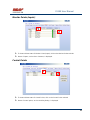
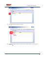
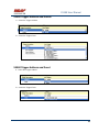
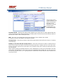
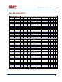
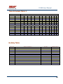
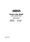
USER MANUAL
REV 1.0
IS100 User Manual
Table of Contents
Overview -------------------------------------------------------------------------------------------------- 5
IS100 Introduction--------------------------------------------------------------------------------------------- 5
Connecting to the IS100 ----------------------------------------------------------------------------- 7
Personnel Manager ------------------------------------------------------------------------------------ 8
Part 1- Cardholder Display ---------------------------------------------------------------------------------- 8
Part 2 – Properties and Functions -------------------------------------------------------------------------- 8
Access Levels ---------------------------------------------------------------------------------------------------------------- 11
Access Functions/Find Record -------------------------------------------------------------------------------------------- 13
Adding a Record ----------------------------------------------------------------------------------------------14
Group Add -----------------------------------------------------------------------------------------------------15
Example 1- Append to Existing Card Records ------------------------------------------------------------------------- 17
Example 2 - Replace Existing Card Records --------------------------------------------------------------------------- 19
Inactivating a Record ----------------------------------------------------------------------------------------21
Group Delete – Inactive Cards -----------------------------------------------------------------------------23
Group Delete – Card Numbers -----------------------------------------------------------------------------25
Re-Index Database--------------------------------------------------------------------------------------------28
Access Levels ----------------------------------------------------------------------------------------- 29
Defining Reader Groups-------------------------------------------------------------------------------------30
Defining Access Levels ---------------------------------------------------------------------------------------34
Time Schedules --------------------------------------------------------------------------------------- 38
Holidays --------------------------------------------------------------------------------------------------------43
Deleting Holidays ---------------------------------------------------------------------------------------------46
Status ---------------------------------------------------------------------------------------------------- 48
Readers ---------------------------------------------------------------------------------------------------------49
Monitor Points (Inputs)--------------------------------------------------------------------------------------51
Control Points -------------------------------------------------------------------------------------------------51
Cameras --------------------------------------------------------------------------------------------------------53
Event Manager ---------------------------------------------------------------------------------------- 56
Reports----------------------------------------------------------------------------------------------------------58
Triggers and Macros -------------------------------------------------------------------------------- 62
Toolbar ---------------------------------------------------------------------------------------------------------62
V1000 Trigger Address and Events -----------------------------------------------------------------------65
V2000 Trigger Address and Event ------------------------------------------------------------------------65
01/07|ICVS450.2
2007© Ness Security Products. All rights reserved.
2
IS100 User Manual
V100 Trigger Address and Events -------------------------------------------------------------------------66
V200 Trigger Address and Events -------------------------------------------------------------------------66
V300 Trigger Address and Events -------------------------------------------------------------------------66
Time Schedule Association ----------------------------------------------------------------------------------67
Sub-Controller Macro Address and Command ---------------------------------------------------------68
V100 --------------------------------------------------------------------------------------------------------------------------- 68
V200 --------------------------------------------------------------------------------------------------------------------------- 68
V300 --------------------------------------------------------------------------------------------------------------------------- 68
Triggers and Macros Example -----------------------------------------------------------------------------69
Hardware Manager----------------------------------------------------------------------------------- 71
Part 1: Toolbar and Hardware System Tree ------------------------------------------------------------71
Backup Data ------------------------------------------------------------------------------------------------------------------ 72
Restore Data ------------------------------------------------------------------------------------------------------------------ 73
Part 2: Hardware (Controller, Sub-Controller, Device) Information ------------------------------74
System Set-up--------------------------------------------------------------------------------------------------74
Controller Properties ----------------------------------------------------------------------------------------75
V1000 ------------------------------------------------------------------------------------------------------------------------- 75
V2000 ------------------------------------------------------------------------------------------------------------------------- 79
Sub-Controller Properties-V100 ---------------------------------------------------------------------------81
AC Power/Battery/Tamper Input Properties ---------------------------------------------------------------------------- 82
Door Contact Properties ---------------------------------------------------------------------------------------------------- 83
Request to Exit Properties ------------------------------------------------------------------------------------------------- 84
Door Strike Properties ------------------------------------------------------------------------------------------------------ 85
Auxiliary Relay Properties------------------------------------------------------------------------------------------------- 86
Reader Properties ------------------------------------------------------------------------------------------------------------ 87
Sub-Controller Properties-V200 ---------------------------------------------------------------------------90
Input Properties (AC Power/Battery/Tamper/Inputs #1-16) --------------------------------------------------------- 91
Relay Properties ------------------------------------------------------------------------------------------------------------- 92
Sub-Controller Properties-V300 ---------------------------------------------------------------------------93
Input Properties (AC Power/Battery/Tamper/Inputs #1 and 2) ------------------------------------------------------ 94
Relay Properties ------------------------------------------------------------------------------------------------------------- 95
Interface to Ness M1 Security System --------------------------------------------------------------------96
Time Schedule Table 1 ----------------------------------------------------------------------------- 98
Time Schedule Table 2 ----------------------------------------------------------------------------- 99
Time Schedule Table 3 ---------------------------------------------------------------------------- 100
Holiday Table ----------------------------------------------------------------------------------------- 100
Reader Group Table 1 ----------------------------------------------------------------------------- 101
Access Level Table 1 ------------------------------------------------------------------------------ 101
Access Level Table 2 ------------------------------------------------------------------------------ 102
Access Level Table 3 ------------------------------------------------------------------------------ 103
01/07|ICVS450.2
2007© Ness Security Products. All rights reserved.
3
IS100 User Manual
Access Level Table 4 ------------------------------------------------------------------------------ 104
01/07|ICVS450.2
2007© Ness Security Products. All rights reserved.
4
IS100 User Manual
Overview
The IS100 User Manual describes the operation of the IS100 software. Use this manual for reference
and daily operation of IS100. If installing the system for the first time, use this manual in conjunction
with the IS100 Installation Guide.
IS100 is a true web-based application that solely resides on the Ness ‘V’ Series controllers. A
dedicated PC is not required. Simply view IS100 via an Internet Explorer browser and you are ready
to go for administration and viewing of real-time events and status of your system.
IS100 consists of the following modules:
•
•
•
•
•
•
•
Personnel Manager
Access Levels
Time Schedules
Status
Event Manager
Triggers and Macros
Hardware Manager
IS100 Introduction
With the seven major modules arranged in tabs, it is easy to navigate. Just click on the tab to go the
appropriate module. The current or active tab will be highlighted blue.
IS100 has common features present in various modules. These common features are outlined below:
•
The Date and Time are displayed right above the tabs and becomes an information bar when
performing certain functions.
•
A progress bar may appear when making updates or changes.
01/07|ICVS450.2
2007© Ness Security Products. All rights reserved.
5
IS100 User Manual
•
Most modules have a simple toolbar
that performs common functions, such
as save, add or delete.
•
When making changes, a save reminder
appears on the top right side of the module.
The save reminder remains until the save button has been clicked.
•
In various modules, the cursor
changes to
indicating that additional commands are
available. Right mouse-click to call up these additional commands.
Each module consists of specific properties and functions. The IS100 User Manual goes through each
module and covers all the corresponding features beginning with the Personnel Manager and ending
with the Hardware Manager. Each section includes screen shots with numbers and letters that
correspond to definitions and functions defined below the figures.
01/07|ICVS450.2
2007© Ness Security Products. All rights reserved.
6
IS100 User Manual
Connecting to the IS100
! If you are not familiar with the network configuration of your facility, please contact
the Network Administrator or IT Manager to perform the steps outlined below.
•
Once all hardware is mounted and wired, initial system set-up and configuration should be
performed with a client computer or laptop that is on the same network as the controller via a
network switch OR while connected directly to the controller with a computer/laptop and an
Ethernet cable.
•
All Ness V1000 & V2000 System controllers are set to DHCP by default out of the factory.
In some cases the IP address may be set for you, and a sticker on the controller will display the IP
address of the unit.
Since you the unit is set to DHCP by default, you may need a tool such as Advance IP Scanner
from www.radmin.com to search for controllers on your network, or you may want to use a factory
set static IP in the unit.
Direct Connect with a factory set static IP
You can use the default static IP address in each V1000 & V2000 of 169.254.242.121.
Step 1:
You need to plug in directly into the V1000 / V2000 with your Ethernet cable.
Step 2:
You need to note down your current IP and network settings on your computer.
Step 3:
Change your computers IP address to 169.254.242.100, with the subnet mask to 255.255.255.0.
Connect With a DHCP IP
If you are connecting to the controller with the DHCP address you need to make sure your computer is
on the same network range.
For example:
If the controllers IP address is: 192.168.0.40 then the computer that will be communicating with the
controller should have the following IP address:’192.168.0.xxx ‘ (xxx can be any number between 2
thru 254, but not the same number that the controller has been pre-programmed with).
01/07|ICVS450.2
2007© Ness Security Products. All rights reserved.
7
IS100 User Manual
Personnel Manager
The Personnel Manager stores pertinent data necessary to manage site access and security. Add,
delete or edit cardholder records. Add up to 8 access levels per cardholder record. Perform group
adds or group deletes. Sort cardholder records by several different parameters. Apply advanced
access functions such as extended access and anti-passback.
1
2
a
b
c
Personnel Manager consists of two main parts: Part
and Part
1
.
2
Part 1- Cardholder Display
Part 1 consists of the Personnel Manager Toolbar, Find Card Record field, and the Cardholder
Population List.
a. The Personnel Manager Toolbar consists of three buttons: Add New Record, Save,
Group Edit. The functions of these buttons are defined below.
Add a New Record.
Save any modifications, changes or edits made in the Personnel Manager.
Perform Group Edit functions, either Group Add or Group Delete.
b. In the Find Card Record, type in either the name (first or last) or the card number and
click
c.
. Sort cardholder list by various parameters. Click
to sort.
The Cardholder Population List displays the cardholders with the corresponding card
numbers.
Part 2 – Properties and Functions
Part 2 consists of the various data fields displaying information for a particular cardholder. When
making changes in these data fields, the field name is italicized and remains so until changes are
saved.
01/07|ICVS450.2
2007© Ness Security Products. All rights reserved.
8
IS100 User Manual
THIS SECTION COVERS THE PROPERTIES AND FUNCTIONS OF THE PERSONNEL MANAGER.
1. First Name. Enter the First Name of the cardholder. In the box following the First Name field,
enter the initial of the middle name.
2. Last Name. Enter the Last Name of the cardholder.
3. Card Format. Click on the drop-down menu. Select the appropriate Card Format, for example
37-bit or 26-bit.
4. Card Status. Click on the drop-down menu. Select the appropriate Card Status.
If card status is INACTIVE, that record will be tagged.
5. Click
01/07|ICVS450.2
to obtain the last card information for this cardholder.
2007© Ness Security Products. All rights reserved.
9
IS100 User Manual
6. Card Number. Enter the Card Number.
7. Pin. If needed, enter the Pin Number.
8. Enter the cardholder Activation Date/Time. Click on the parameter: month, day, year or time
and type in the appropriate information when highlighted. See below.
The month is
highlighted.
Alternatively, click on the drop-down menu and select the appropriate date. To scroll through
the months, click on the left or right buttons shown below.
Click here
to scroll.
9.
Enter the cardholder Expiration Date/Time. Repeat as described in step # 8.
01/07|ICVS450.2
2007© Ness Security Products. All rights reserved.
10
IS100 User Manual
Access Levels
1. To assign one or more access levels to a card record, hover over the Access Levels window.
2. The cursor changes to
, indicating that additional commands are available. Right
mouse-click to call up a popup menu.
3. Highlight ‘Add Access Level’ from the popup menu to display all 10 access levels. Select the
preferred access level, in this example, Part Time-Lobby.
01/07|ICVS450.2
2007© Ness Security Products. All rights reserved.
11
IS100 User Manual
4.
Part Time-Lobby has been added.
5. To remove an access level, simply select the appropriate access level and right mouse-click.
Go to ‘Remove Selected Access Level’.
6.
Part Time-Lobby has been removed.
7. Add up to 8 access levels per cardholder. When the maximum number of access levels is
reached ‘A maximum of 8 Access Levels are allowed per record’ is displayed on the
information bar.
Up to eight (8) access levels can be assigned to a cardholder.
For more information on creating access levels, please go to the Access Level section.
01/07|ICVS450.2
2007© Ness Security Products. All rights reserved.
12
IS100 User Manual
Access Functions/Find Record
1. Under Access Functions, the following features can be selected:
The cardholder will be exempt from anti-passback conditions.
The cardholder will be granted extended access grant time. This is commonly used for
ADA settings.
For more information on defining anti-passback conditions and the extended access
grant time please go to the Hardware Manager section.
2. To find a specific record or card number, type in the name or the number. Press <Enter> or
click on the
binoculars. Continue to click on the binoculars to advance to the next
cardholder record with the same name.
3. To sort records, click
01/07|ICVS450.2
. Next, select how the records should be sorted.
2007© Ness Security Products. All rights reserved.
13
IS100 User Manual
Adding a Record
1. To add a new record, click
. A new slot appears.
2. For the new record, enter the appropriate cardholder information and click
.
3. Once saved, the cardholder is displayed in the cardholder list.
01/07|ICVS450.2
2007© Ness Security Products. All rights reserved.
14
IS100 User Manual
Group Add
In addition to adding a single card, a group add can also be performed. This is especially useful if the
group of cards to be added is in a sequence.
1. To Group Add, click
.
2. A ‘Personnel Manager: Group Edit’ window appears. Define the specified parameters:
A. Checking TRUE, will APPEND the specified cards to the existing cardholder records.
Leaving this FALSE will create new records with the specified card number range and
DELETE existing cardholder records.
B. Enter the Starting Card# sequence and the Ending Card# sequence.
C. The card format will default to the correct one.
D. Enter the Activation Date and the Deactivation Date.
01/07|ICVS450.2
2007© Ness Security Products. All rights reserved.
15
IS100 User Manual
3. Scroll down to display more parameters.
E. Define up to 8 Access Levels for the specified card range:
Choose from 10
pre-defined
Access Levels
(1-10).
F. To apply either Passback Exempt or Extended Access or both parameters to the
specified card range, mark as True. To not apply any or all parameters leave blank,
False.
4. In Example 1 below, the following Group Add was performed:
01/07|ICVS450.2
2007© Ness Security Products. All rights reserved.
16
IS100 User Manual
Example 1- Append to Existing Card Records
•
•
•
•
•
Append to the Existing Cards: True
Card Range: 264-270
Card Format: 26 Bit
Activation Date 1/1/2007, Deactivation Date 12/31/2037
Access Level A: 1
5. Once the parameters are specified, click
. A ‘Group Add?’ message dialog will
appear. The message dialog reconfirms that the specified card numbers will be added to the
existing card database. Click Yes.
01/07|ICVS450.2
2007© Ness Security Products. All rights reserved.
17
IS100 User Manual
6. A green progress bar will appear. When complete the newly specified card numbers will be
added to the existing cardholder records.
7. The new cardholder records are shown below.
Old Cardholder Records
New Cardholder Records
Append to Existing
Card Records
01/07|ICVS450.2
2007© Ness Security Products. All rights reserved.
18
IS100 User Manual
8. To add names to the new records, simply click on the record and enter the name in the
appropriate fields. Click
.
9. If after adding a cardholder name, the next record is selected without saving the previous
cardholder name, the following message dialog will appear. Click Yes.
10. In Example 2 below, the following Group Add was performed:
Example 2 - Replace Existing Card Records
•
•
•
•
•
Append to the Existing Cards: False
Card Range: 264-270
Card Format: 26 Bit
Activation Date 1/1/2007, Deactivation Date 12/31/2037
Access Level A: 1
01/07|ICVS450.2
2007© Ness Security Products. All rights reserved.
19
IS100 User Manual
11. Once the parameters are specified, click
. A ‘Group Add?’ message dialog will
appear. The message dialog reconfirms that NEW cardholder records will be created,
DELETING the existing cardholder records. Click Yes, if this is true.
! EXERCISE CAUTION WHEN PERFORMING THIS FUNCTION. ALL
EXISTING CARDHOLDERS WILL BE
DELETED.
12. A green progress bar will appear (see # 6 above). When complete the newly specified card
numbers will replace existing cardholders.
13. The new cardholder records are shown below.
Old Cardholder Records
New Cardholder Records
Replace Existing
Card Records
01/07|ICVS450.2
2007© Ness Security Products. All rights reserved.
20
IS100 User Manual
Inactivating a Record
1. To inactivate a record, first select the cardholder.
2. Change the Card Status to ‘INACTIVE’.
3. Click
01/07|ICVS450.2
.
2007© Ness Security Products. All rights reserved.
21
IS100 User Manual
4. Once SAVED the cardholder record will be tagged in two locations: the Card Status will be
displayed as red INACTIVE and the cardholder record will appear red in the cardholder list.
Another cardholder record (Record ID # 11 of 13) has also been tagged inactive.
!
Card Records are indexed by the record ID#, which is tied to all history and events,
including the record name. It is RECOMMENDED that when a card record or card records
are no longer utilized they should be made inactive and left in the database. These records
are tagged inactive and are no longer functional.
If a group of cards require deletion, FIRST run a report for all events in the Event Manager
(see the Event Manager section for more information). Save and print the report to obtain a
hard copy.
Once reports have been generated and saved/printed, delete the appropriate cards as
described in the sections that follow.
01/07|ICVS450.2
2007© Ness Security Products. All rights reserved.
22
IS100 User Manual
Group Delete – Inactive Cards
Group deletes (or single card deletes) can be performed by either deleting card(s) that have been
tagged inactive or entering in the card number(s). This section outlines how Inactive Cards are
deleted.
1. To Group Delete, click
.
2. To delete INACTIVE cards, click on the first option.
01/07|ICVS450.2
2007© Ness Security Products. All rights reserved.
23
IS100 User Manual
3. Click
. A ‘Group Delete?’ message dialog will appear. The message dialog
reconfirms that the INACTIVE card record(s) will be deleted. Click Yes, if this is true.
! EXERCISE CAUTION WHEN PERFORMING THIS FUNCTION.
4. A green progress bar will appear.
5. When complete the tagged cardholders are deleted. Since the cardholders have been sorted
by record ID, the available slots appear in the same location as the deleted cardholders.
01/07|ICVS450.2
2007© Ness Security Products. All rights reserved.
24
IS100 User Manual
6. Two new cardholders have been added to Record ID #11 and Record ID # 12. Once added,
the cardholders were sorted by Card Number.
Group Delete – Card Numbers
Group deletes (or single card deletes) can be performed by either deleting card(s) that have been
tagged inactive or entering in the card number(s). This section outlines how Cardholders with a
specified card range can be deleted.
01/07|ICVS450.2
2007© Ness Security Products. All rights reserved.
25
IS100 User Manual
1. To Group Delete, click
.
2. To delete Cardholders with a specified card range, click on the second option and type in the
card range. In this example, card range is 271-272.
To delete a SINGLE card, enter card number for the Starting Card# and the Ending Card#.
3. Click
. A ‘Group Delete?’ message dialog will appear. The message dialog
reconfirms that the card(s) with the specified card range will be deleted. Click Yes, if this is
true.
! EXERCISE CAUTION WHEN PERFORMING THIS FUNCTION.
01/07|ICVS450.2
2007© Ness Security Products. All rights reserved.
26
IS100 User Manual
4. A green progress bar will appear.
5. When complete the cardholders with the specified card range are deleted. Since the
cardholders have been sorted by Card Number, the available slots appear on the very top of
the cardholder list.
01/07|ICVS450.2
2007© Ness Security Products. All rights reserved.
27
IS100 User Manual
Re-Index Database
The Re-Index Database function verifies the integrity of the associated card#s and the record IDs.
Perform this function when multiple add and/or delete functions are performed.
1. To Re-Index, click
.
2. Click on ‘Re-Index Database’.
3. A ‘Re-Index Database?’ message dialog will appear. Click Yes, if this is true.
01/07|ICVS450.2
2007© Ness Security Products. All rights reserved.
28
IS100 User Manual
Access Levels
Access Levels consists of a reader or a group of readers with a Time Schedule association. The
Access Levels module consists of two sub-tabs: Reader Groups and Access Levels. In the Reader
Groups sub-tab, assign a single reader or multiple readers to a Reader Group. In the Access Levels
sub-tab, the Reader Groups can be associated to a Time Schedule and then assigned to an access
level.
Reader Groups
Define up to 10 Reader Groups.
Access Levels
Define up to 10 Access Levels.
THIS SECTION COVERS READER GROUPS AND ACCESS LEVELS.
01/07|ICVS450.2
2007© Ness Security Products. All rights reserved.
29
IS100 User Manual
Defining Reader Groups
To set-up Access Levels, first define the reader group(s) by assigning a reader or a multiple readers to
the selected Reader Group.
1. Click on the Reader Groups tab.
2. Readers in communication with Ness ‘V’ Series controllers ‘V’ Series controllers will autopopulate in the Readers window.
3. Click to select a Reader Group (1-10) from the drop-down menu.
01/07|ICVS450.2
2007© Ness Security Products. All rights reserved.
30
IS100 User Manual
4. Click on the readers to add to the Reader Group. To deselect, simply click on the reader
again.
5. Click
to add readers to the Reader Group. Click
Reader Group.
to remove readers from the
6. The selected readers have now been placed under Reader Group 1.
7. To rename the Reader Group, click
.
8. After clicking
01/07|ICVS450.2
on
2007© Ness Security Products. All rights reserved.
, the buttons will
31
IS100 User Manual
change to
.
9. Type in the new name and click on
changes click on
to update the new Reader Group. To disregard the
.
Two readers (O.R.1: Lobby and O.R.2: Side Entrance) have been assigned to the All Readers reader group.
01/07|ICVS450.2
2007© Ness Security Products. All rights reserved.
32
IS100 User Manual
Two new reader groups are defined: Lobby and Side Entrance.
The save reminder will appear when any change is made.
When multiple changes are needed, simply make all the changes, click
when complete.
A ‘Changes Saved Successfully’ dialog box will appear. Click OK.
01/07|ICVS450.2
2007© Ness Security Products. All rights reserved.
33
IS100 User Manual
Defining Access Levels
To define an Access Level, assign Reader Group(s) with an associated Time Schedule to the selected
Access Level.
1. To create access level(s), click on the Access Levels tab.
2. The three (3) reader groups that were defined will appear in the Reader Groups window.
3. Time schedules will appear in the Time Schedules window.
For more information on creating time schedules, please go to the Time Schedule section.
01/07|ICVS450.2
2007© Ness Security Products. All rights reserved.
34
IS100 User Manual
4. Click to select an Access Level (1-10) from the drop-down menu.
5. Click on one or more Reader Groups and an associated Time Schedule. To deselect, simply
click the highlighted item again.
6. Click
to add the Reader Group(s) with the associated Time Schedule to the selected
Access Level. Click
to remove the Reader Group(s) from the Access Level.
7. The Reader Group – All Readers with the associated Time Schedule (1) has been assigned
to Access Level 1.
01/07|ICVS450.2
2007© Ness Security Products. All rights reserved.
35
IS100 User Manual
8. To rename the Access Level, click
9. After clicking on
, the buttons will change to
10. Type in the new name and click on
changes click on
01/07|ICVS450.2
.
.
to update the new Access Level. To disregard the
.
2007© Ness Security Products. All rights reserved.
36
IS100 User Manual
Reader Group 1 – ‘All Readers’ with Time Schedule 1 association has been
assigned to the All Readers (7-6:30) Access Level.
Two new Access Levels are defined: Part Time- Lobby and Lobby- Normal, Side-P/T.
01/07|ICVS450.2
2007© Ness Security Products. All rights reserved.
37
IS100 User Manual
The save reminder will appear when any change is made.
Time Schedules
When multiple changes are needed, simply make all the changes, click
when complete.
A ‘Changes Saved Successfully’ dialog box will appear. Click OK.
In Time Schedules, define schedules that can be used in association with Access Levels and Reader
Groups. Typically, the Time Schedule determines when a door is accessed. The Time Schedules
module consists of two sub-tabs: Time Schedules and Holidays. In the Time Schedules sub-tab,
define schedules and the hours and days of the week (including Holidays) in which this schedule is
applicable. In the Holidays sub-tab, define Holidays that are observed.
Time Schedules
Define up to 6 Time Intervals per Time Schedule and up to 12 Time Schedules.
01/07|ICVS450.2
2007© Ness Security Products. All rights reserved.
38
IS100 User Manual
Holidays
Define up to 12 Holidays.
THIS SECTION COVERS TIME SCHEDULES.
1. To create a new time schedule, first click on the drop-down menu
01/07|ICVS450.2
2007© Ness Security Products. All rights reserved.
.
39
IS100 User Manual
2. Select the first available Time Schedule. In this example, three (3) Time Schedules have
been created.
3. Click
01/07|ICVS450.2
to name the new Time Schedule.
2007© Ness Security Products. All rights reserved.
40
IS100 User Manual
4. Enter in the name of the new Time Schedule.
5. Once the new name has been entered, click
window. Click
01/07|ICVS450.2
to acknowledge the name and close the
to close the window without acknowledging any changes.
2007© Ness Security Products. All rights reserved.
41
IS100 User Manual
6. Enter in the Begin and End time.
Use military time for Begin and End time.
7. Place a check mark under the days of the week that will follow the schedule.
8. If applicable, place a check mark under the Holiday Groups that will also follow the Interval:
H1, H2, H3 and/or H4.
9. Click
to save changes. A ‘Changes have been Saved!’ message dialog will appear.
Click OK.
Up to 6 Intervals can be assigned to a Time Schedule.
For more information on creating Holiday Groups, please go to the Holidays
section.
Time Schedule 4 ‘Normal Business Hours (8:00am to 5:30pm)’ will GRANT
ACCESS between 0800 and 1700 Monday thru Friday and during Holiday Groups:
H1 and H2.
01/07|ICVS450.2
2007© Ness Security Products. All rights reserved.
42
IS100 User Manual
Holidays
1. To create holiday(s), click on the Holidays Tab.
2. In this example, four (4) holidays have been created.
3. To add a new holiday, click
01/07|ICVS450.2
.
2007© Ness Security Products. All rights reserved.
43
IS100 User Manual
4. A ‘New Holiday’ is added.
5. Click on the Group. Click on the drop-down menu and select which Holiday Group to assign
this holiday to: 1=H1, 2=H2, 3=H3 and 4=H4.
01/07|ICVS450.2
2007© Ness Security Products. All rights reserved.
44
IS100 User Manual
6. Enter in the name (Description) of the holiday.
7. Enter the date the holiday will be observed. Type in the numbers or click on the up/down
arrows to scroll through.
8. Place a check mark in the repeating box if the holiday occurs on the same date every year.
9. Another holiday, Valentine’s Day is created.
01/07|ICVS450.2
2007© Ness Security Products. All rights reserved.
45
IS100 User Manual
Deleting Holidays
1. To delete a holiday, click on the appropriate holiday.
2. Click
.
3. A ‘Delete Holiday?’ message dialog will appear. Click Yes.
The save reminder will appear when any change is made.
01/07|ICVS450.2
2007© Ness Security Products. All rights reserved.
46
IS100 User Manual
01/07|ICVS450.2
2007© Ness Security Products. All rights reserved.
47
IS100 User Manual
Status
The Status module displays a real-time view of the current condition of devices on the system. The
status of each device is displayed under the corresponding sub-tabs: Readers, Monitor Points and
Control Points. Readers and Control Points can be controlled by command buttons when a specific
device is selected. Under the Cameras sub-tab, IP addresses for DVRs and/or individual IP Cameras
can be entered (up to 16 views / addresses) and then triggered to pop-up in a viewing window.
Associated camera functions can be used on this page while viewing the camera.
THIS SECTION COVERS STATUS FOR READERS, MONITOR POINTS
(INPUTS), CONTROL POINTS AND CAMERAS
01/07|ICVS450.2
2007© Ness Security Products. All rights reserved.
48
IS100 User Manual
Readers
1. View real-time status of Readers.
Doors (readers) can follow Time Schedules. Please see the Access Levels section.
2. To manually Unlock a Door, Lock a Door, or Momentarily Unlock a Door, first click on the
appropriate reader.
3. The first reader with address 0.R.1, Lobby, is currently unlocked. To lock the door, click on
the Lock Door button.
4. The status has been changed to Locked.
01/07|ICVS450.2
2007© Ness Security Products. All rights reserved.
49
IS100 User Manual
5. Under Readers, the cursor changes to
, indicating that additional commands are
available on a right mouse-click. These commands can change the state of the reader LEDs
and the beeper to ON or OFF.
6. To change the state of the LEDs and/or beeper, first select the appropriate reader. Right
mouse-click to call up the popup menu.
7. Go to the option that requires the change. For example, to turn the Red LED off, go to Red
LED and select OFF.
01/07|ICVS450.2
2007© Ness Security Products. All rights reserved.
50
IS100 User Manual
Monitor Points (Inputs)
1. To view real-time status of Monitor Points (Inputs), click on the Monitor Points sub-tab.
2. Status of inputs, such as Door Contacts, is displayed.
Control Points
1. To view real-time status of Control Points, click on the Control Points sub-tab.
2. Status of control points, such as Auxiliary Relays, is displayed.
01/07|ICVS450.2
2007© Ness Security Products. All rights reserved.
51
IS100 User Manual
3a
3b
3. There are two ways to manually Activate a Relay, Deactivate a Relay or Pulse a Relay. First
click on the appropriate relay (control point).
, indicating that additional
a. Under Control Points, the cursor changes to
commands are available on a right mouse-click. These commands include: Activate
a Relay, Deactivate Relay, and Pulse Relay. To perform any of these commands,
simple click on the command.
-ORb. Click on the command from the Relay buttons.
4. Aux Relay #1 with address 0.01 is active. To deactivate the relay, click on the relay and click
on the Deactivate Relay button.
5. The status has been changed to Normal.
01/07|ICVS450.2
2007© Ness Security Products. All rights reserved.
52
IS100 User Manual
Cameras
1. To view live video, click on the Cameras sub-tab.
2. To add IP cameras, Digital Video Recorders (DVR), or Network Video Recorders (NVR),
double click on the Camera Description. If some slots are already in use, simply double-click
on the next available one.
01/07|ICVS450.2
2007© Ness Security Products. All rights reserved.
53
IS100 User Manual
3. Type in the Camera Description.
4. Scroll to the right.
5. Double-click on the URL slot. Type in the URL.
01/07|ICVS450.2
2007© Ness Security Products. All rights reserved.
54
IS100 User Manual
6. Click on Live Video.
7. A new window displaying live video of the selected camera is launched.
01/07|ICVS450.2
2007© Ness Security Products. All rights reserved.
55
IS100 User Manual
Event Manager
The Event Manager displays real-time events from the system. View events and generate various
system-wide reports.
1. To go to the Event Manager, click on the Event Manager tab.
When connecting to Ness ‘V’ Series controllers, events are buffered on the
controller and are not displayed. These events can easily be retrieved, see
#2 below.
01/07|ICVS450.2
2007© Ness Security Products. All rights reserved.
56
IS100 User Manual
The events occurring after connecting to Ness ‘V’ Series
controllers are reported.
2. To retrieve events stored on Ness ‘V’ Series controllers, click
and select ‘Retrieve ALL
Event History’.
3. All events are now displayed, beginning with the most recent event. Scroll to view the events.
01/07|ICVS450.2
2007© Ness Security Products. All rights reserved.
57
IS100 User Manual
Reports
1. Once all events are retrieved, reports can be generated. Click
01/07|ICVS450.2
2007© Ness Security Products. All rights reserved.
.
58
IS100 User Manual
2. A Report Criteria window opens. Specify the report parameters.
3. Enter the Start Date for the report. Enter the date manually or select the date from the
calendar. Use
to scroll through, click on the appropriate date.
4. Enter the End Date for the report. Enter the date manually or select the date from the
calendar. Use
to scroll through, click on the appropriate date.
5. The Name/Description field represents information under the Data column in the Event
Manager. Type in the name/description, i.e. cardholder name.
01/07|ICVS450.2
2007© Ness Security Products. All rights reserved.
59
IS100 User Manual
6. Select a specific event for the report.
7. An example of a report criteria, run a report for any cardholder with the name of Smith and has
had Access Denied: Access Level from 01/01/2006 to 11/29/2006.
8. After these parameters have been entered, click on ‘Preview Report’.
01/07|ICVS450.2
2007© Ness Security Products. All rights reserved.
60
IS100 User Manual
9. A .txt report is returned. This report can be saved, printed, and/or emailed.
10. Once reporting is complete, simply click
01/07|ICVS450.2
to return to the Event Manager.
2007© Ness Security Products. All rights reserved.
61
IS100 User Manual
Triggers and Macros
The Triggers and Macros module allows programming of procedures based on specific events. A
Trigger is defined as an event that occurs in the system with specific properties. These Triggers are
linked to execute Macros. A Macro is a command or a set of sequential commands put together.
Triggers and Macros can be programmed to occur during defined Time Schedules
Toolbar
The Triggers and Macros Toolbar consists of three buttons: Add, Save, and Delete. The
functions of these buttons are defined below.
Adds a New Trigger.
Saves any modifications, changes, and edits made in Triggers and Macros.
Deletes an existing Trigger.
1. To go to Triggers and Macros, click on the Triggers and Macros tab.
2. To add a trigger, click
01/07|ICVS450.2
.
2007© Ness Security Products. All rights reserved.
62
IS100 User Manual
3. Click
to expand the Properties and Values.
4. Expanding reveals the properties and values, which are defined below. To collapse the tree,
simply click .
01/07|ICVS450.2
2007© Ness Security Products. All rights reserved.
63
IS100 User Manual
5. To delete a trigger, select the appropriate trigger. Click
.
6. A ‘Delete Trigger?’ message dialog will appear. The message dialog reconfirms that the
selected Trigger will be deleted. Click Yes.
7. A trigger name can be added to the Trigger and Macro. Simply click on the New Trigger to
highlight. Type in the name.
8. Define the address that the trigger will originate from. Choose from the controllers (V1000 or
V2000) or the sub-controllers that are installed. Next, select the event which will initiate the
trigger.
Once the Trigger Address has been defined, the Trigger Events will
change accordingly. Where applicable, scroll down to see all the Trigger
Events.
01/07|ICVS450.2
2007© Ness Security Products. All rights reserved.
64
IS100 User Manual
V1000 Trigger Address and Events
A. Select the Trigger Address
B. Select the Trigger Event
V2000 Trigger Address and Event
A. Select the Trigger Address
B. Select the Trigger Event
01/07|ICVS450.2
2007© Ness Security Products. All rights reserved.
65
IS100 User Manual
V100 Trigger Address and Events
A. Select the Trigger Address
B. Select the Trigger Event
V200 Trigger Address and Events
A. Select the Trigger Address
B. Select the Trigger Event
V300 Trigger Address and Events
01/07|ICVS450.2
2007© Ness Security Products. All rights reserved.
66
IS100 User Manual
A. Select the Trigger Address
B. Select the Trigger Event
Time Schedule Association
9. Select the Time Schedule that the Trigger and Macro will follow.
10. Define the address that will execute the macro and the command that will be executed.
Choose from the controllers (V1000 or V2000) or the sub-controllers that are installed.
Once the Macro Address has been defined, the Macro Events will change
accordingly. Where applicable, scroll down to see all the Macro Events.
01/07|ICVS450.2
2007© Ness Security Products. All rights reserved.
67
IS100 User Manual
Sub-Controller Macro Address and Command
V100
A. Select the Macro Address
B. Select the Macro Command
V200
A. Select the Macro Address
B. Select the Macro Command
V300
A. Select the Macro Address
B. Select the Macro Command
01/07|ICVS450.2
2007© Ness Security Products. All rights reserved.
68
IS100 User Manual
Triggers and Macros Example
The following Triggers and Macros example illustrates how to associate a Door to a Time Schedule.
Door 1 configuration on the V100 (on-board V2000) consists of a Door Contact, REX, Door Strike, Aux
Relay and Reader. For this example, the Door 1 Strike Relay will follow the Normal Business
Hours (8:00am to 5:00pm) Time Schedule. The Door Strike Relay will only be active when the Time
Schedule is active.
To perform this Trigger and Macro the following parameters are set:
•
Trigger Description: Door 1 – Time Schedule Link
•
Address: 32 – V2000
•
Event: S – Time Schedule Link
•
Time Schedule: 4 – Normal Business Hours (8:00am to 5:00pm)
•
Macro Address: 0 - V100
•
Macro Command: 0:0 – Door 1 Strike Relay: Link
01/07|ICVS450.2
2007© Ness Security Products. All rights reserved.
69
IS100 User Manual
The save reminder will appear when any change is made.
When multiple changes are needed, simply make all the changes, click
when complete.
A ‘Changes Saved Successfully’ dialog box will appear. Click OK.
! Any changes saved in Triggers and Macros take affect after one (1) minute.
01/07|ICVS450.2
2007© Ness Security Products. All rights reserved.
70
IS100 User Manual
Hardware Manager
The Hardware Manager is used for initialization and configuration of all hardware and devices on the
system. Define properties for inputs, relays, and readers. Auto-scan and automatically configure
connected sub-controllers. Backup Data or Restore Data to/from a specified file.
1
2
a
b
Hardware Manager consists of two main parts: Part
1
and Part
2
.
Part 1: Toolbar and Hardware System Tree
a. The Hardware Manager Toolbar consists of two buttons: Save and Backup/Restore Data. The
functions of these buttons are defined below.
Saves any modifications, changes, and edits made in the Hardware Manager.
Backup Data or Restore Data to/from a specified file.
01/07|ICVS450.2
2007© Ness Security Products. All rights reserved.
71
IS100 User Manual
Backup Data
1. To Backup Data, click on the button, and select Backup Data.
2. A ‘Backup Database‘ dialog box will appear. This will include the exact path of the backup
files. Click OK.
3. A progress bar will appear during the backup process.
.
! The Backup will occur on the computer that is being used
to communicate with the controller at that time.
01/07|ICVS450.2
2007© Ness Security Products. All rights reserved.
72
IS100 User Manual
Restore Data
1. To Restore Data, click on the button, and select Restore Data.
2. A ‘Restore Database’ dialog box will appear. To restore the database, the data files will be
restored from the computer and the path that the files were originally backed up to.
3. A progress bar will appear during the restoring process.
! Exercise caution when performing this function. Restoring database
will OVERWRITE the existing database on the controller.
01/07|ICVS450.2
2007© Ness Security Products. All rights reserved.
73
IS100 User Manual
1
2
a
b
b. The Hardware System Tree displays all the hardware in a hierarchy. The controllers
(V1000/V2000) are displayed on top, sub-controllers are next, followed by inputs, outputs/relays, and
readers. Click on a specific hardware or device from the Hardware System Tree to display the
corresponding properties on the Hardware Information window to the right.
, indicating that additional
While on the Hardware System Tree window, the cursor changes to
commands are available on a right mouse-click. Additional commands are available for controllers,
sub-controllers, control points (door strikes and relays) and readers. Please see the specific hardware
or device below for these commands.
Part 2: Hardware (Controller, Sub-Controller, Device) Information
The Hardware Information displays the properties and values for the selected hardware or device from
the Hardware System Tree. The Hardware Information displays Controller Information, Sub-Controller
Information and Sub-Controller Device Information.
System Set-up
When a new system is installed, go to Hardware Manager. Perform an auto scan with the controller to
scan the network for all sub-controllers that are in communication with the controller. Once Auto Scan
is complete the system will automatically populate the Hardware System Tree. To modify any of the
settings, simply click on the hardware or device from the Hardware System Tree to display
corresponding properties and values in the Hardware Information window.
THIS SECTION COVERS HARDWARE INFORMATION DEFINITIONS FOR ALL
HARDWARE AND DEVICES.
01/07|ICVS450.2
2007© Ness Security Products. All rights reserved.
74
IS100 User Manual
Controller Properties
Properties for both controllers, V1000 and V2000, are displayed on the Controller Information window
when the controller is selected from the Hardware System Tree.
V1000
1. To view and set properties, click on the controller from the Hardware System Tree to display
controller dependent properties under the Controller Information.
Controller Properties that can be modified:
•
•
•
•
Set Date/Time
Time Zone
Network Configuration
Admin Password
Please see the IS100 Quick Set-Up Guide for more information.
Controller Properties that cannot be modified:
•
•
•
•
•
•
•
•
•
01/07|ICVS450.2
MAC Address
IP Address
Host Name
Internal ID
Board Type
App version
App Date
Cards Loaded
Card Capacity
2007© Ness Security Products. All rights reserved.
75
IS100 User Manual
2. The
cursor indicates that additional commands are available on a right mouse-click.
Click on the controller, right mouse-click to display two commands: Autoscan for Subcontrollers and Reset Controller.
•
Autoscan for Sub-controllers - Auto scans the network for all sub-controllers that are in
communication with the controller and populates and configures the hardware
automatically.
•
Reset Controller - Resets all of the tasks on the controller.
! The Reset Controller command should only be used for troubleshooting.
01/07|ICVS450.2
2007© Ness Security Products. All rights reserved.
76
IS100 User Manual
3. The following Inputs are present on the controller:
•
•
•
•
•
AC Power Input
Battery Input
Tamper Input
Input #1
Input #2
These inputs have two properties that can be modified:
Input Supervision - Determines if the input will be wired as normally open, normally closed,
with or without end-of-line (EOL) resistors. When inputs are wired with resistors, select the
appropriate values, i.e. 1k = Normal, 2k = Alarm.
Debounce Time - Sensitivity setting for inputs that ranges from 0-2040 milliseconds. The
debounce setting requires the system to receive this number of consecutive readings without
deviation before the system reports a change of state or an alarm.
01/07|ICVS450.2
2007© Ness Security Products. All rights reserved.
77
IS100 User Manual
4. Modify the Relay property:
•
Pulse Time: The amount of time the relay stays active. Time ranges between 0-512
seconds.
•
The
cursor indicates that additional commands are available on a right mouse-click.
Click on the Relay and right mouse-click. The following commands appear:
o
o
o
Activate Relay
Deactivate Relay
Pulse Relay
Click on a command to perform the function.
01/07|ICVS450.2
2007© Ness Security Products. All rights reserved.
78
IS100 User Manual
V2000
The V2000 has the same properties displayed in the Controller Information window as described for
the V1000 above. The three inputs: AC Power Input, Battery Input, Tamper Input are shown below the
on-board V100.
1. To view and set properties, click on the controller from the Hardware System Tree to display
controller dependent properties under the Controller Information.
Controller Properties that can be modified:
•
•
•
•
Set Date/Time
Time Zone
Network Configuration
Admin Password
Please see the IS100 Quick Set-Up Guide for more information.
Controller Properties that cannot be modified:
•
•
•
•
•
•
•
•
•
01/07|ICVS450.2
MAC Address
IP Address
Host Name
Internal ID
Board Type
App version
App Date
Cards Loaded
Card Capacity
2007© Ness Security Products. All rights reserved.
79
IS100 User Manual
2. The
cursor indicates that additional commands are available on a right mouse-click.
Click on the controller, right mouse-click to display two commands: Autoscan for Subcontrollers and Reset Controller.
•
Autoscan for Sub-controllers - For the V2000 controller, the auto scan will populate and
configure the on-board V100 sub-controller.
•
Reset Controller - Resets all of the tasks on the controller.
! The Reset Controller command should only be used for troubleshooting.
01/07|ICVS450.2
2007© Ness Security Products. All rights reserved.
80
IS100 User Manual
Sub-Controller Properties-V100
Click on the sub-controller (V100) to display real-time status of both the sub-controller and all on-board
inputs. Click on the individual inputs/relays/readers to display specific properties.
1. On the hardware tree, click on the sub-controller, V100.
2. Sub-Controller dependent properties are displayed. These include:
•
Address: Address of the board (0)
•
Board Type: Type of board (V100)
•
Status of the sub-controller:
When first connecting, the status will be POLLING.
Once communication is established, the status will change to ONLINE.
•
Status of the inputs REX, Door Contacts, Tamper, AC Power, and Battery:
Normal
Active
3. The
cursor indicates that additional commands are available on a right mouse-click.
Click on the sub-controller and right mouse-click. A ‘Reset Sub-Controller’ command
appears. Click on this command if a reset is required.
01/07|ICVS450.2
2007© Ness Security Products. All rights reserved.
81
IS100 User Manual
AC Power/Battery/Tamper Input Properties
•
Enabled -True or False. If True, device will report to the system and be monitored.
•
Input Supervision - Determines if the input will be wired as normally open, normally
closed, with or without end-of-line (EOL) resistors. When inputs are wired with resistors,
select the appropriate values, i.e. 1k = Normal, 2k = Alarm.
•
Debounce Time - Sensitivity setting for inputs that ranges from 0-2040 milliseconds. The
debounce setting requires the system to receive this number of consecutive readings
without deviation before the system reports a change of state or an alarm.
01/07|ICVS450.2
2007© Ness Security Products. All rights reserved.
82
IS100 User Manual
Door Contact Properties
•
Enabled -True or False
•
Input Supervision - Determines if the input will be wired as normally open, normally
closed, with or without end-of-line (EOL) resistors. When inputs are wired with resistors,
select the appropriate values, i.e. 1k = Normal, 2k = Alarm.
•
Debounce Time - Sensitivity setting for inputs that ranges from 0-2040 milliseconds. The
debounce setting requires the system to receive this number of consecutive readings
without deviation before the system reports a change of state or an alarm.
•
Door Held Open Time – The time a door can remain open before being considered Door
Held Open. The time ranges from 0-512 seconds.
01/07|ICVS450.2
2007© Ness Security Products. All rights reserved.
83
IS100 User Manual
Request to Exit Properties
•
Enabled -True or False. If True, device will report to the system and be monitored.
•
Input Supervision - Determines if the input will be wired as normally open, normally
closed, with or without end-of-line (EOL) resistors. When inputs are wired with resistors,
select the appropriate values, i.e. 1k = Normal, 2k = Alarm.
•
Debounce Time - Sensitivity setting for inputs that ranges from 0-2040 milliseconds. The
debounce setting requires the system to receive this number of consecutive readings
without deviation before the system reports a change of state or an alarm.
•
REX Mode – Determines whether to activate a door strike or not to activate a door strike.
01/07|ICVS450.2
2007© Ness Security Products. All rights reserved.
84
IS100 User Manual
Door Strike Properties
•
Access Grant Time: The amount of time that the door will remain unlocked upon an
access granted event. The time range is between 0-512 seconds.
•
The
cursor indicates that additional commands are available on a right mouse-click.
Click on the Door Strike and right mouse-click. The following commands appear:
o
o
o
Unlock Door
Lock Door
Momentarily Unlock Door
Click on a command to perform the function.
01/07|ICVS450.2
2007© Ness Security Products. All rights reserved.
85
IS100 User Manual
•
Auto Unlock Time Schedule: If the door is to be automatically unlocked during a
programmed time schedule, then select the time Schedule and the door will auto unlock
and relock during these times. .
Note 1. When programming this option during a Time Schedule, then the door may not unlock
immediately and you may have to wait for the top of the next minute for it to Auto Unlock.
Therefore wait for at least 2 minutes when first programming to confirm its operation. Once the
time schedule passes to the next day it will occur during the start of the Time Schedule.
Note 2. If the Door is unlocked during the Time Schedule and then it is manual relocked by an
operator via the IS100 software it will remain locked and the Time Schedule will be overridden
for this day only. If it is then unlocked manually unlocked via the IS100 software it will then
relock at the end of the Time Schedule.
Auxiliary Relay Properties
•
Pulse Time: The amount of time the relay stays active. Time ranges between 0-512
seconds
01/07|ICVS450.2
2007© Ness Security Products. All rights reserved.
86
IS100 User Manual
•
The
cursor indicates that additional commands are available on a right mouse-click.
Click on the Aux Relay and right mouse-click. The following commands appear:
o
o
o
Activate Relay
Deactivate Relay
Pulse Relay
Click on a command to perform the function.
Reader Properties
•
Description: Type in the reader description/name.
•
The
cursor indicates that additional commands are available on a right mouse-click.
Click on the Reader and right mouse-click. The following commands appear:
o
o
o
Unlock Door
Lock Door
Momentarily Unlock Door
Click on a command to perform the function.
01/07|ICVS450.2
2007© Ness Security Products. All rights reserved.
87
IS100 User Manual
•
Access Grant Time: The amount of time that the door will remain unlocked upon an
access granted event. The time range is between 0-512 seconds.
•
Extended Access Grant Time: The amount of time that the door will remain unlocked
upon an access granted event to a cardholder with extended access grant time. Typically
this property is used for ADA settings. The time range is between 0-512 seconds.
•
Minimum Open Time: The time a door can remain open before being considered Door
Held Open. The time range is between 0-512 seconds.
•
Reader Mode: Possible method by which a user can open a door.
The allowed values have the following interpretations:
•
PIN Suppression Schedule: ID number of a PIN suppression schedule. If the reader is a
card-and-pin reader, then this schedule determines when this reader becomes in effect a
card-only reader. The schedule itself is one of the set defined in the schedules file.
•
PIN Support: 0- False, 1- True
•
Reader Type: 0- None, 1- Wiegand, 2- Clock and Data
01/07|ICVS450.2
2007© Ness Security Products. All rights reserved.
88
IS100 User Manual
•
Elevator Reader: 0- False, 1- True
•
Anti-Passback: Applies anti-passback rules that are either timed (in seconds) to
determine the interval before a cardholder can gain entry through the same reader or hard
in which anti-passback is implemented throughout a system with entry and exit readers to
defined areas within the controlled access area.
•
Anti-Passback Timeout: Number of seconds that a timed anti-passback is in effect (the
current time – last card read time) for a user must be greater than the timeout for the antipassback period to be over.
•
Anti-Passback Action: Action to be taken if an anti-passback or area violation is
detected.
•
Anti-Passback Area In: Area that the door leads into (0-255).
01/07|ICVS450.2
2007© Ness Security Products. All rights reserved.
89
IS100 User Manual
•
Anti-Passback Area Out: Area that the door leads from (0-255).
Sub-Controller Properties-V200
Click on the sub-controller (V200) to display real-time status of both the sub-controller and all on-board
inputs. Click on the individual inputs and relays to display specific properties. V200 has 16 inputs and
2 auxiliary relays. The V200 also has inputs for AC Power, Battery, and Tamper.
1. On the hardware tree, click on the sub-controller, V200.
2. Sub-Controller dependent properties are displayed. These include:
•
Address: Address of the board (20)
•
Board Type: Type of board (V200)
•
Status of the sub-controller:
When first connecting, the status will be POLLING.
01/07|ICVS450.2
2007© Ness Security Products. All rights reserved.
90
IS100 User Manual
Once communication is established, the status will change to ONLINE.
•
Status of inputs: Tamper, AC Power, Battery and the 16 inputs
Normal
Active
Input Properties (AC Power/Battery/Tamper/Inputs #1-16)
All the inputs have the following properties:
•
Enabled -True or False. If True, device will report to the system and be monitored.
•
Input Supervision - Determines if the input will be wired as normally open, normally
closed, with or without end-of-line (EOL) resistors. When inputs are wired with resistors,
select the appropriate values, i.e. 1k = Normal, 2k = Alarm.
01/07|ICVS450.2
2007© Ness Security Products. All rights reserved.
91
IS100 User Manual
•
Debounce Time - Sensitivity setting for inputs that ranges from 0-2040 milliseconds. The
debounce setting requires the system to receive this number of consecutive readings
without deviation before the system reports a change of state or an alarm.
Relay Properties
Both relays (# 1and # 2) have the following property:
•
Pulse Time: The amount of time the relay stays active. Time ranges between 0-512
seconds.
01/07|ICVS450.2
2007© Ness Security Products. All rights reserved.
92
IS100 User Manual
•
The
cursor indicates that additional commands are available on a right mouse-click.
Click on the Relay and right mouse-click. The following commands appear:
o
o
o
Activate Relay
Deactivate Relay
Pulse Relay
Click on a command to perform the function.
Sub-Controller Properties-V300
Click on the sub-controller (V300) to display real-time status of both the sub-controller and all on-board
outputs/relays and inputs. Click on the individual relays and inputs to display specific properties.
V300 has 12 outputs/relays and 2 auxiliary inputs. The V300 also has inputs for AC Power, Battery
and Tamper.
1. On the hardware tree, click on the sub-controller, V300.
2. Sub-Controller dependent properties are displayed. These include:
•
Address: Address of the board (21)
•
Board Type: Type of board (V300)
•
Status of the sub-controller:
When first connecting, the status will be POLLING.
01/07|ICVS450.2
2007© Ness Security Products. All rights reserved.
93
IS100 User Manual
Once communication is established, the status will change to ONLINE.
•
Status of inputs: Tamper, AC Power, Battery and the 2 auxiliary inputs
Normal
Active
Input Properties (AC Power/Battery/Tamper/Inputs #1 and 2)
All the inputs have the following properties:
•
Enabled -True or False. If True, device will report to the system and be monitored.
•
Input Supervision - Determines if the input will be wired as normally open, normally
closed, with or without end-of-line (EOL) resistors. When inputs are wired with resistors,
select the appropriate values, i.e. 1k = Normal, 2k = Alarm.
01/07|ICVS450.2
2007© Ness Security Products. All rights reserved.
94
IS100 User Manual
•
Debounce Time - Sensitivity setting for inputs that ranges from 0-2040 milliseconds. The
debounce setting requires the system to receive this number of consecutive readings
without deviation before the system reports a change of state or an alarm.
Relay Properties
All Relays (#1-12) have the following property:
•
Pulse Time: The amount of time the relay stays active. Time ranges between 0-512
seconds.
01/07|ICVS450.2
2007© Ness Security Products. All rights reserved.
95
IS100 User Manual
•
The
cursor indicates that additional commands are available on a right mouse-click.
Click on the Relay and right mouse-click. The following commands appear:
o
o
o
Activate Relay
Deactivate Relay
Pulse Relay
Click on a command to perform the function.
Interface to Ness M1 Security System
The V1000 and V2000 controllers can communicate to the Ness M1 Security control panel via the
TCP/IP connection. A good TCP Ethernet connection must remain in place for this to occur.
If Security Panel settings are
programmed
in
the
Hardware Manager for the
controller, then when Person
Manager is option M1 user
code options will become
available. If there is not IP or
other setting for the Security
Panel then these options will
not appear.
Security Panel Network IP is the IP address of the M1 Ethernet module. The M1 must have an
Ethernet module present on the same network for interfacing to be available.
Security Panel Network Port – This is the port programmed into the M1 Ethernet module. This port
must be made active in the M1 Ethernet for communications to be established. (Please refer M1
Ethernet manual)
Security Panel PIN. – This is the Master Code as programmed in code 1 in the M1. If this code is
changed in the M1 then it must also be changed her or communications will be lost.
01/07|ICVS450.2
2007© Ness Security Products. All rights reserved.
96
IS100 User Manual
If the security panel
communications is set
within the Hardware
Manager as per
above, then Security
User ID can be
programmed in the
Personnel Manager.
Security User ID – Although the IS100 system supports up to 5,000 users, the M1 supports 198 user
codes (2-199) for Arming and Disarming the Security System. The Security User ID allocates which of
the 198 user codes is to be used by this user.
PIN – This is the 4 (or 6) digit PIN code the user will use to Arm or Disarm the m1 with.
To delete a user this code needs to be set back to 0000.
Security Areas – These are the Areas of the M1 Security panel the user will have access to in Arming
and Disarming.
Deleting a user from the M1 Security Panel the PIN Code should be set back to 0000 and then
saved. Once saved if you wish to free up the Security User ID so another user can use it then set it
back to User 000. If you wish to reserve this User in the M1 for this user for future use then leave it set
at a User ID No.
Note: If left to anything except 000 when the code is deleted then no other user will be able to use that
code space and depending on how many users are programmed into the M1 then you may run out of
M1 Security Systems users, so it is good practice to set this back to 000 after the code is deleted and
account is saved.
01/07|ICVS450.2
2007© Ness Security Products. All rights reserved.
97
IS100 User Manual
Time Schedule Table 1
TIME SCHEDULE 1
INTERVAL
BEGIN
1
2
3
4
5
6
TIME SCHEDULE 2
INTERVAL
BEGIN
1
2
3
4
5
6
TIME SCHEDULE 3
INTERVAL
BEGIN
1
2
3
4
5
6
TIME SCHEDULE 4
INTERVAL
BEGIN
1
2
3
4
5
6
TIME SCHEDULE 5
INTERVAL
BEGIN
1
2
3
4
5
6
01/07|ICVS450.2
END
MON
TUES
WED
THURS
FRI
SAT
SUN
H1
H2
H3
H4
END
MON
TUES
WED
THURS
FRI
SAT
SUN
H1
H2
H3
H4
END
MON
TUES
WED
THURS
FRI
SAT
SUN
H1
H2
H3
H4
END
MON
TUES
WED
THURS
FRI
SAT
SUN
H1
H2
H3
H4
END
MON
TUES
WED
THURS
FRI
SAT
SUN
H1
H2
H3
H4
2007© Ness Security Products. All rights reserved.
98
IS100 User Manual
Time Schedule Table 2
TIME SCHEDULE 6
INTERVAL
BEGIN
1
2
3
4
5
6
TIME SCHEDULE 7
INTERVAL
BEGIN
1
2
3
4
5
6
TIME SCHEDULE 8
INTERVAL
BEGIN
1
2
3
4
5
6
TIME SCHEDULE 9
INTERVAL
BEGIN
1
2
3
4
5
6
TIME SCHEDULE 10
INTERVAL
BEGIN
1
2
3
4
5
6
01/07|ICVS450.2
END
MON
TUES
WED
THURS
FRI
SAT
SUN
H1
H2
H3
H4
END
MON
TUES
WED
THURS
FRI
SAT
SUN
H1
H2
H3
H4
END
MON
TUES
WED
THURS
FRI
SAT
SUN
H1
H2
H3
H4
END
MON
TUES
WED
THURS
FRI
SAT
SUN
H1
H2
H3
H4
END
MON
TUES
WED
THURS
FRI
SAT
SUN
H1
H2
H3
H4
2007© Ness Security Products. All rights reserved.
99
IS100 User Manual
Time Schedule Table 3
TIME SCHEDULE 11
INTERVAL
BEGIN
1
2
3
4
5
6
TIME SCHEDULE 12
INTERVAL
BEGIN
1
2
3
4
5
6
END
MON
TUES
WED
THURS
FRI
SAT
SUN
H1
H2
H3
H4
END
MON
TUES
WED
THURS
FRI
SAT
SUN
H1
H2
H3
H4
Holiday Table
GROUP
01/07|ICVS450.2
DESCRIPTION
2007© Ness Security Products. All rights reserved.
DATE
REPEATING
100
IS100 User Manual
Reader Group Table 1
READER GROUP
DESCRIPTION
READER GROUP 1
READER GROUP 2
READER GROUP 3
READER GROUP 4
READER GROUP 5
READER GROUP 6
READER GROUP 7
READER GROUP 8
READER GROUP 9
READER GROUP 10
Access Level Table 1
ACCESS LEVEL 1
READER GROUPS
TIME SCHEDULE
ACCESS LEVEL 2
READER GROUPS
TIME SCHEDULE
01/07|ICVS450.2
2007© Ness Security Products. All rights reserved.
101
IS100 User Manual
Access Level Table 2
ACCESS LEVEL 3
READER GROUPS
TIME SCHEDULE
ACCESS LEVEL 4
READER GROUPS
TIME SCHEDULE
ACCESS LEVEL 5
READER GROUPS
TIME SCHEDULE
01/07|ICVS450.2
2007© Ness Security Products. All rights reserved.
102
IS100 User Manual
Access Level Table 3
ACCESS LEVEL 6
READER GROUPS
TIME SCHEDULE
ACCESS LEVEL 7
READER GROUPS
TIME SCHEDULE
ACCESS LEVEL 8
READER GROUPS
TIME SCHEDULE
01/07|ICVS450.2
2007© Ness Security Products. All rights reserved.
103
IS100 User Manual
Access Level Table 4
ACCESS LEVEL 9
READER GROUPS
TIME SCHEDULE
ACCESS LEVEL 10
READER GROUPS
TIME SCHEDULE
01/07|ICVS450.2
2007© Ness Security Products. All rights reserved.
104
IS100 User Manual
NOTES
01/07|ICVS450.2
2007© Ness Security Products. All rights reserved.
105
IS100 User Manual
Rev 1.1 May 2012
Document Part No: 890-xxx
For the products:
101-049 V1000 IP ACCESS CONTROLLER
101-053 V2000 IP ACCESS CONTROLLER
Innovative Electronic Solutions
www.ness.com.au
NSW
Ph 02 8825 9222
[email protected]
VIC
Ph 03 9875 6400
[email protected]
QLD
Ph 07 3399 4910
[email protected]
WA
Ph 08 9328 2511
[email protected]
SA
Ph 08 8152 0000
[email protected]
All rights reserved. No part of this publication may be reproduced, transmitted or stored in a retrieval system in any form or by any
means, electronic, mechanical, photocopying, recording, or otherwise, without the prior written permission of Ness.
Ness reserves the right to make changes to features and specifications at any time without prior notification in the interest of ongoing
product development and improvement.
© 2012 Ness Corporation Pty Ltd ABN 28 069 984 372