1
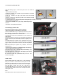
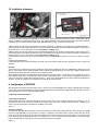
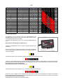
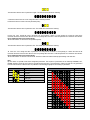
Note
Before using the system GRIPONE read every page of this manual. The installation of this device requires attention and accuracy. The
configuration of the device requires several non-trivial reflections, referred to only within this manual. Please note that you are installing a
device on a vehicle can reach high speeds. The system GRIPONE is a professional and not approved for use on road.
Contens of the kit
N.1 ECU
N.1 Plug&lay harness
N.2 Speed sensor
N.1 User manual
Safety
During the installation of this product, it is recommended to position the motorbike in such a way that is cannot cause any injury or
damage by falling down or moving forward or backward; it is recommended to use the rear stand or, if necessary, the wheel lock. Make
sure that the injection system is always turned off and that the electrical equipment is not being powered during the installation of this
product (and, as well as, during all assembly phases indicated in this manual). When adding or removing electrical cables or wiring
to/from the motorcycle’s equipment, always be sure to remove the negative battery terminal before the positive battery terminal. During
reassembly phases, connect the negative terminal last in order to avoid short circuiting the electrical equipment
Installation reccomandations
DO NOT RUSH! When installing the GRIPONE control unit, make sure that the unit is protected from excessive vibrations and
surrounding elements and that it is clamped firmly. When you use the adhesive parts (for setting up the control unit or cables), make
sure that the mounting surfaces are clean and free of dust or grease by cleaning them with degreasing solution. When positioning the
wiring, make sure that the wires cannot be pinched or crushed which may cause subsequent malfunctions, clamp them as necessary.
For safe and professional assembly, it is recommended that you solder the connections when possible and use thermo-tightening bands
to isolate the various conductors. Place the hot part of the welder on the ends of the wires before putting them in contact with each
other. Do not hesitate to contact the vendor/supplier for assistance if you encounter any difficulties with the installation of this device.
WARNING! The GRIPONE control unit must be placed where the operating temperature does not exceed 65°C and should be installed
where it will be protected from vibrations and surrounding elements. Locate a flat surface on which to secure the control unit. Do not
secure the unit until the installation of all other components has been completed and the wiring has been secured.
1.Whats is GRIPONE and how it works
I In sports, every bike is continually found to be in critical situations in which the rear wheel loses its grip during acceleration. GRIPONE
is a universal device, designed to be easily attached to any vehicle and through which it is possible to control the level of sliding at the
rear wheel. Moment by moment, GRIPONE checks the conditions of the motorbike on which it is mounted and manages the power to
restore the optimal running conditions, increasing stability and improving the overall yield..
GRIPONE is an electronic traction control system consisting of two elements: the GRIPONE control unit and two speed sensors.
Working in unison, they continuously monitor the traction conditions for the motorcycle. Under normal circumstances (i.e. when no
sliding is occurring), the control unit does not intervene in any way with the motorcycle.
When above-normal sliding is detected, the control unit reduces the engine power until normal roadholding is restored. Once the rear
tire re-establishes correct adhesion and the sliding is detected to be within the accepted threshold, the control unit ceases to reduce the
engine power
2. Electric connection
The installation of the system involves connecting the GRIPONE control unit to the harness of the motorcycle and fit the two speed
sensors in close proximity to both wheels The installation of the GRIPONE control unit is possible on all motorcycles with inductive or
transistor ignitions (or on bikes with electronic fuel injection). The GRIPONE control unit cannot be installed on CDI control. Connecting
the GRIPONE control unit to CDI type ignition, it will be damaged.
2.1 Connection by plug & play cable
Follow the following steps to connect the system to the wire harness of
vehicle.
1. Remove fuel tank and airbox;
2. Unplug the connector from a ignition coil (we recommend to disconnect
one of the outer cylinder);
3. Plug the connector A of plug & play cable to the coil previously
disconnected.
4. Plug the connector A of plug & play cable to the connector previously
disconnected from the coil.
5. Connect the black wire of the plug & play cable to the negative pole of battery or to the frame.
6. Relocate the airbox and the tank.
7. Connect the GRIPONE ECU to plug & play cable through 5-pole
connector;
8. Secure the unit using fixing tape included
2.2 Connecting by universal cable
Please follow the following steps for electrical connection.
1. Be sure that the bike is off and battery is disconnected.
2. Place the GRIPONE ecu by the special tape included into the kit.
Please choose a position far from hot please (engine, exhaust pipe).
Near to head pipe or tachometer are recommended.
3. Connect the included cable to GRIPONE ecu by the “superseal” 5
pole connector.
4. Connect the black wire to the frame by the included ring tongues. Be
sure that the chosen point is electrically connected to negative pole of
battery.
5. Find the positive pole of ignition coil (or single injector for cylinder).
To find the positive pole the user can check all the wire of all ignition
coils (or injector). The one that is common to all coils is the positive
pole.
6. Cut the positive pole of ignition coil (on injector) near to the
connector. (fig.1)
7. Connect the red and blue wire (of GRIPONE cable) to the A end (fig.
1) by the heatshrincable head junction (fig. 2).
8. Connect the yellow wire (of GRIPONE cable) to the B end (fig. 1) by
the heatshrincable head junction (fig. 3).
9. Cut the negative pole of other coil (or other injector). Don’t use the
same coil chosen in steps 6, 7 and 8.
10. Connect the green wire (of GRIPONE cable) to the two ends
created in step 9 (fig.4)
2.3 Main switch
Onto the cable included into the kit there is a lever switch that
allow you to activate or not the traction control system. On the
switch there is a thread that allow you to fix it to the stirrup in a
specific way (see the picture ). On the thread there is a elongate
furrow who guide a washer with a tab. Tab fix the verse of
mounting. When the lever is set to the left the traction control
system is operative. When the lever is set to the right the traction
control system is off.
NOTE
Even with the traction control unactive the ECU stay on.
3.0 Installation of sensors
To measure the speed of the bike the GRIPONE ecu use two sensor, one for each wheel. The sensors consist of a filleted M8x1 cylinder
which is connected to the signal cable (already wired). The connectors that are located at the ends of the cable of the sensors should be
connected to the two 3-pole connectors located on the GRIPONE control unit (fig. 7). Follow the following step.
1. Make a support for front sensor The front sensor must detect the passage of minimum 3 or maximum 6 bolt of front brake disk (fig.5).
2. Fix the front sensor to the support and adjust its to the correct distance to disk bolt. The sensors detect the passage of a bolt if it is not
further away than 1.5 mm or closer than 0.5 mm. Locking torque = 0.5 Kg/m. (fig.5)
3. Make a support for rear sensor The rear sensor must detect the passage of 3 or more bolt of rear brake disk (or rear sprocket). (fig. 6)
4. Fix the rear sensor to the support and adjust its to the correct distance to disk bolt. The sensors detect the passage of a bolt if it is not
further away than 1.5 mm or closer than 0.5 mm. Locking torque = 0.5 Kg/m. (fig.6)
5. Connect the front sensor to the 3 pole connector placed on the right (on GRIPONE ecu) and the rear sensor to connector on the left.
(fig. 7)
6. Switch on the GRIPONE ecu.
7. Check that both sensors detect the passage of the bolt. If the sensor detect correctly the bolt a led (placed on back of sensor) will
switch on.
Important
It is important not to confuse the front sensor with the rear sensor when connecting two sensors to GRIPONE ecu. Please refer to the
figure 7. The proximity sensors should be applied to the motorcycle through rigid brackets, so that at every complete revolution of the
wheel they detect the passage from a minimum of 3 to maximum of 6 bolt.
When installing the sensors in correspondence with the fixing screws of the disk brake or of the rear crown, be careful not to use (as
ferrous objects) hollow head screws (like hollow screws or bolts or Allen head screws). If the motorcycle is equipped with this type of
screws, it is necessary to replace them with full head screws. Every ferrous object detected by the sensor should be equidistant from
the others. If these two conditions are not satisfied, the system will not function correctly.
4. Configuration of GRIPONE
After the electrical connection and positioning of sensors, the user must set the GRIPONE ECU correctly to obtain the right functioning
of the system. On the front panel there are 3 red leds (called Parameter leds) and 8 yellow leds (called Value leds). All of this are used to
give a easy interface to the user during the setting operations.
4.1 Meaning of standard parameter
4.1 Spinning (1° parameter)
This parameter fix the level of spinning needed to activate the control. The user can adjust this parameter from minimum of 1 to 8.
Increasing the value the ecu will be less sensible to the loosing of grip. The value 1 correspond to the maximum sensibility of the
system. The value 8 correspond to the minimum sensibility of the system.
Value: 1-8
4.2 Cut (2° parameter)
The parameter “cut” determine the intensity of the control (when the ecu redeem the excessive spinning). When the level of spinning
become too high GRIPONE cut a part of power. The value 1 correspond to the minimum effect on power control: when ecu cut the
power, the power drop is very small. The value 8 correspond to the maximum effect on power control: when ecu cut the power, the
power drop is very big. Increasing the parameter “cut” (scrolling it from 1 to 8) it’s possible to increase the effect of control on the engine
power. If this parameter is 0 (zero) the ecu does not decrease the power in any condition.
Value: 1-8
4.3 Engine (3° parameter)
The value of “engine” parameter depend on installation of system on the bike. If the installation is made by plug & play cable the “engine”
must be fixed to 0 (zero). If the installation is made by universal cable it depend on RPM signal. If the green wire of GRIPONE cable is
connected to the ignition coil Engine must be fixed to 0. If the green wire of GRIPONE cable is connected to the pickup on crankshaft the
“engine” parameter must be fixed to 1.
Value: 0-1
4.4 Ratio (4° parameter)
The Ratio parameter informs the GRIPONE control unit on the ratio between the development of rear tire and front tire (Rear
Development / Front Development). Based on the development of tires set this parameter according to the values reported in table 1.
Value: 1-8
4.5 Pulse (5° parameter)
The “pulse” parameter inform the ecu about the numbers of pulse detected by each speed sensors for a complete wheel revolution.
Based on the number of pulses detected by the front and rear sensors, set this parameter according to the values reported in table 2.
Value: 0-15
Rotolamento ruota anteriore - front wheel dimension (cm)
Table 1
185
186
187
188
189
190
191
192
193
194
195
196
197
198
199
200
201
202
203
204
195
3
3
2
2
2
1
1
1
0
0
0
196
3
3
3
2
2
2
1
1
1
0
0
0
197
4
3
3
3
2
2
2
1
1
1
0
0
0
198
4
4
3
3
3
2
2
2
1
1
1
0
0
0
Rotolamento ruota posteriore - rear wheel dimension (cm)
199 200 201 202 203 204 205 206
4
5
5
5
6
6
6
7
4
4
5
5
5
6
6
6
4
4
4
5
5
5
6
6
3
4
4
4
5
5
5
6
3
3
4
4
4
5
5
5
3
3
3
4
4
4
5
5
2
3
3
3
4
4
4
5
2
2
3
3
3
4
4
4
2
2
2
3
3
3
4
4
1
2
2
2
3
3
3
4
1
1
2
2
2
3
3
3
1
1
1
2
2
2
3
3
0
1
1
1
2
2
2
3
0
0
1
1
1
2
2
2
0
0
0
1
1
1
2
2
0
0
0
1
1
1
2
0
0
0
1
1
1
0
0
0
1
1
0
0
0
1
0
0
0
207
7
7
6
6
6
5
5
5
4
4
4
3
3
3
2
2
2
1
1
1
208
7
7
7
6
6
6
5
5
5
4
4
4
3
3
3
2
2
2
1
1
209
8
7
7
7
6
6
6
5
5
5
4
4
4
3
3
3
2
2
2
1
210
8
8
7
7
7
6
6
6
5
5
5
4
4
4
3
3
3
2
2
2
Table 2
Pulses of rear wheel
Pulses of front wheel
Value to set
3
3
0
3
3
4
5
1
2
3
6
3
4
3
4
4
4
4
5
5
6
4
6
7
5
3
8
5
5
4
5
9
10
5
6
11
6
3
12
6
6
4
5
13
14
6
6
15
Value show by leds
4.2 CONFIGURATION Mode
The GRIPONE has three different modes: ON, CONFIGURATION and
ADVANCED. When you switch on the ECU the ON mode is activated. In this
mode the three parameter leds are flashing.
To configure the parameters the user must activate the CONFIGURATION
mode.
Please follow the following step to configure the ecu.
1. Switch on the GRIPONE ecu. The ecu must be in ON mode (parameter leds
are flashing).
2. Push the P button on front panel (one time) to activate the configuration
mode. The first parameter (spinning) will be selected. The Value leds show the
value of this parameter.
The Value leds show the value of parameter “spinning”. The default value should be the following:
3. If the user want change the value of parameter “spinning” must push the V button. For each pushing of V button the value will be
increased until the its maximum value allowed. One more pushing will fix the value of selected parameter to its minimum value allowed.
Every modification will be saved automatically.
4. Push the P button to switch to the next parameter (cut).
The Value leds show the value of parameter “cut”. The default value should be the following:
5. If the user want change the value of parameter “cut” must push the V button. For each pushing of V button the value will be
increased until the its maximum value allowed. One more pushing will fix the value of selected parameter to its minimum value allowed.
Every modification will be saved automatically.
6. Push the P button to switch to the next parameter (engine).
The Value leds show the value of parameter “engine”. The default value should be the following:
7. Push the V button if the user want change the value of selected parameter.
8. Push the P button to switch to the next parameter (Ratio).
The Value leds show the value of parameter “ratio”. The default value should be the following:
9. If the user want change the value of parameter “cut” must push the V button. For each pushing of V button the value will be
increased until the its maximum value allowed. One more pushing will fix the value of selected parameter to its minimum value allowed.
Every modification will be saved automatically.
10. Push the P button to switch to the next parameter (Pulse).
The Value leds show the value of parameter “ratio”. The default value should be the following:
11. If the user want change the value of parameter “cut” must push the V button. For each pushing of V button the value will be
increased until the its maximum value allowed. One more pushing will fix the value of selected parameter to its minimum value allowed.
Every modification will be saved automatically.
12. Push the P button to switch in to the ON mode. The return to ON mode will be indicate by rapid flashing of all value leds..
Note:
By the P button it’s possible scroll all the configuration parameters. The sequence of parameters are the following: SPINNING, CUT,
ENGINE, RATIO e PULSE. By the V button it’s possible increase the value of each parameters. Please note that not every parameters
have the same numbers of allowed value. Pay attention to the following paragraph for the meaning of parameters
LED “PARAMETER”
PARAMETER
LED “PARAMETER”
VALUE
Spinning (1-8)
0
Cut (0-8)
1
Engine (0-1)
2
Ratio (0-8)
3
Pulse (0-15)
4
5
6
7
8
9
10
11
12
13
14
15
4.3 ON Mode
Into the ON mode the leds Parameter are flashing slowly (2 times/sec). The leds Value can flash or stay on (or off) according to the state
of GRIPONE ECU.
LED VALUE
Fast flashing of leds Value
(4 times/sec)
DESCRIPTION OF STATE
If the bike is stoped or the speed of the bike is very low: The ECU reed a speed
under the minimum (< 12 kmh).
If the bike goes normally (>12Kmh): one sensor (or both) is broken or does not work
correctly. ECU stop the control automatically and goes to standby mode.
Leds off
The speed of bike is over than 12 Kmh and there is not spinning on rear tyre.
Leds on
The speed of bike is over than 12 Kmh and there is spinning on rear tyre.
.
= 1° level of spinning
= 2° level of spinning
= 3° level of spinning
= 4° level of spinning
4.4 ADVANCED Mode
The ADVANCED Mode gives the opportunity to the user to adjust two more parameter: Speed e Remote. To activate the ADVENCED
Mode keep pushing (3 sec) the button P. All leds parameter will switch on and will stay on until user release the button. The leds
parameter will show the parameter Speed:
To modify the value of parameter Speed push button V. each pushing will increase the value of Speed until its maximum. One more
pushing reset the value to the minimum. The range of Speed is 1 to 8.
Pushing one more time the button P the parameter Remote will be showed:
To modify the value of parameter Remote push button V. each pushing switch the value from 1 to 0 and viceversa.
One more pushing of button P will bring back the ECU to ON Mode.
4.4.1 Speed
This parameter allow the user to set the character of traction control according to the bike speed. In slow corner the bike need more
quick reaction by traction control because the turning radius in is very small. On fast corner the traction control must be mainly stable to
avoid the shaking. For that reason the traction control system must change a bit the character of control according to the bike speed.
This parameter allow the user to set this trend: fixing Speed to 1 this trend is almost null, fixing Speed to 8 this trend is very effective.
Valori: 1-8
4.4.2 Remote
The GRIPONE ECU can be connected to two different accessories: standard remote control and analog remote control. The first
one (standard) give the opportunity to change the sensibility by a lever switch (placed on the handlebar). The second one (analog) give
the opportunity to change the value of spinning by a potentiometer (placed on the tachometer). The parameter Remote inform the ECU
about which type of remote control is connected. If the user use a standar remote control (or none) the parameter Remote must be set to
1. If the user use a analog remote control the parameter Remote must be set to 0.
5. How best configure the unit
5.1 Logic operation
Once fixed the parameters “engine”, “pulse” e “ratio” these will remain the same in every condition. The other two parameters
(”spinning” and “cut”) are used to optimize the system to the user preferences.
Please follow this step to obtain a right setup of ECU:
1. Fix Spinning to 1 and Cut to 8. In this way it’s very easy to feel the effect of traction control. May be this configuration will be too
invasive.
2. Try to increase the Spinning value (from 1 to 8) until the rider cannot feel the effect of traction control anymore. Then come back of 1
or 2 step with value of Spinning.
3. When the timing of traction control is good enough the user can adjust the amount control on the power. Actually with Cut = 8 the
traction control system could be too invasive. To reduce the dropping of power the user can decrease the value of Cut (from 8 to 1).
IMPORTANT:
The algorithm the calculate the spinning of rear tyre modify the amount of cut (on the engine power) by the spinning level. That means
that when the ECU calcolate a small spinning the cut on the power will be small. When the spinning on rear tyre is big, the cut on the
power will be (proportionally) big.
5.2 External factors that influence the functioning
The GRIPONE can be influenced by some external condition. The first factor than can influence the system is the type of engine of the
bike. The same regulation of the system can be right for a 4 cylinder engine and wrong for 2 cylinder engine. For this reason we suggest
to adjust the parameter “cut” on based of the type of engine. For two cylinders cut should be fix between 1 and 7, For four cylinders cut
should be fix between 3 and 8.
Another factor that can influence the work of the system is tyres profile. Using a racing profile tyres the real develop of the tyre change by
the angle of leaning. In that condition the system can be quite sensible at the maximum angle of leaning and less sensible at the mid
angle. Please adjust the parameter “spinning” to avoid a excessive sensitive at maximum angle (increasing this parameter).
ATENTION
Please keep in mind that the traction control system does not preclude crash caused by
a wrong use of the throttle of the veichle in general. For this reason we suggest to test
the work of the system and its effect on the byke carefully. Please try the different
regulation by small step and do not exaggerate with the use of throttle.
6. Accessories – Remote control
The control unit GRIPONE is designed for connecting the Remote control, a device that enables the display of control activity. The
Remote control, once connected and positioned so as to be visible while driving, inform the rider when the traction control system comes
into operation. At any time the GRIPONE reduce the engine power the red led of Remote control is switched on.
The Remote control also allows you to change the sensitivity of the system in real time, while driving the bike. Using the lever (positioned
on the handlebar by the plate included), or a potentiometer, you can change the sensitive of base map pre set in GRIPONE. Acting to
the remote switch the sensitivity is varied as you were acting on the parameter spinning.
7. Features
Features
Power:
Dimensions:
Weight:
Min speed:
Max speed:
Max Revs
Min dimension of front tyre:
Max dimension of front tyre:
Min dimension of rear tyre:
Max dimension of rear tyre:
Wheel pulses for revolution
Rif.
11-18 volt
78x52x28 (mm)
200g
about 30 Kmh
about 360 Kmh
about 20000 RPM
185 cm
220 cm
185 cm
220 cm
min 3 – max 6
8. Sensors
Features
Type:
Power:
Output:
Schield:
Sensing distance
Operating frequency:
Dimension:
Operating temperature:
Material:
Torque::
Description
inductive proximity
12-24 Volt
NPN NO – open collector
yes
max 2mm
0 – 1500 Hz
M8 x 1
-40° +85°
steel inox
max 0.5 Kg/m
Made by
di Diego Gubellini
Via Fiorentina 3508/H
40059 Medicina (BO) Italy
PI 02132331204
CF GBLDGI75L02A944H
[email protected]
www.gripone.com
Official vendor
www.GRIPONE.com
www.GRIPONE.com