1
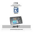
UN0°
USE AND MAINTENANCE INSTRUCTIONS
CONTENTS
1. Safety recommendations
2. Table of warning and attention plates
3. Description of the machine
4. Description of the controller
4.1. Starting the controller
4.1.1. Standard
4.1.2. Multi-temperature version
4.2. Setting diesel operation
4.3. Setting the work set point
4.3.1. Standard
4.3.2. Multi-temperature version
4.4. Enabling and disabling evaporators (only Multi-temperature version)
4.5. Starting the refrigerating unit
4.6. Manual defrost
4.7. Alarms
4.8. Alarm list
4.9. Description of alarms
4.10.
Diesel operation lock (engine lock)
4.11.
Service
4.12.
Maintenance
4.12.1. Maintenance A
4.12.2. Maintenance B
4.12.3. Maintenance C
4.12.4. Maintenance D
4.12.5. Further maintenance instructions
5. Storage and stacking
6. Mobile partitions
7. How to use the refrigerating unit in the best way
8. Safe use
8.1. Engine coolant
8.2. Refrigerant
8.3. Battery
9. Troubleshooting
10. How to order spare parts
11. Warranty
12. How to dispose of the packing
13. How to dispose of the unit
2
Thank you for choosing Transblock. Please read these instructions carefully. They provide details and advice
on the correct method of installing, using and maintaining this unit, in order to obtain maximum reliability,
efficiency and long life
1. Safety reccomandations
When installing and using the unit please follow the recommendations listed here below.
•
•
•
•
•
The machine should be installed according to the diagrams and instructions given by the manufacturer.
Any damage due to improper connections is excluded.
The neutral conductor, even if grounded, is not accepted as a safety conductor.
The electric installation of the place where the unit is installed must comply with the regulations in force
applicable to electrical installations.
Maintenance shall be effected by trained personnel or by the manufacturer according to the provisions
supplied by EN378.
ATTENTI ON
Use safety gloves to protect your hands from possible cuts.
The user is strongly recommended to contact the manufacturer before attempting any intervention on the
unit and any use not corresponding to the manufacturer’s indications (in particular as for the field of
application) and to enquire about the possible dangers and contra-indications connected with an improper
use of the machine.
•
The unit shall be used following these instructions and sticking to the destination of use indicated by the
supplier. Any incorrect use can result in damage to the unit and represents a serious danger for people’s
health.
ATTENTION
The unit is not suitable for working in explosive environments.
Therefore the use of the unit in an explosion-dangerous atmosphere is absolutely
forbidden.
ATTENTI ON
The unit is not suitable for w orking in salty environm ents. I n such a case protect
condenser and evaporator w ith appropriate m eans.
When maintenance involves operations on the cooling circuit, drain the system and let it reach the
atmospheric pressure.
W ARN I NG
Do not discharge the refrigerant in the atm osphere. I t m ust be recovered by
specialised technicians using a suitable equipm ent.
•
•
•
•
Quantity and quality of the refrigerant to be charged are indicated on the data plate.
Do not use refrigerants of different
kind
(especially inflammable refrigerants, for example
hydrocarbons) or air.
No modifications or changes in the refrigerating circuit or in components (such as: welding on
compressor body) are allowed.
The final user shall protect the unit from external fire dangers.
3
The unit has been so built as to maintain a constant temperature in the cold room during transport.
This requires the load compartment to be equipped with a closing system ensuring perfect tightness, so
that on unloading the product has a correct temperature; in addition when loading and arranging the
product in the cold room make sure that it is perfectly ventilated.
• Should a product be loaded at an excessive temperature, the unit will not be able to cool it, as this
operation does not fall within the use it is intended for.
The following recommendations are supplied for a safe use of the refrigerating unit:
•
•
ATTENTI ON
•
•
•
•
•
•
•
Do not use any water or steam jets for cleaning purposes: they could damage the electric
components of the unit.
Keep the radiating masses of condenser and evaporator clean and free from obstructions.
When the unit is connected to the mains, and in particular when it is in a closed environment, check
that the condenser is not obstructed or too near the walls; in addition make sure that air circulation
is adequate.
Check that all securing screws are properly tightened and suitable for the intended use.
When boring the unit or the vehicle frame, pay attention not to bore any refrigerating pipe, electric
wire or any other component.
Never close the compressor relief valves when the unit is operating.
In case of operations on the unit, only use pressure gauges in good conditions. Do not put them in
contact with any belts, with the pulley or the fan.
W ARN I NG
Carry out cleaning and maintenance operations only when the unit is still.
After a certain period of operation the condenser and the high-pressure delivery pipes are
particularly hot; wait for the unit to cool before any operation on it.
• The unit includes moving parts such as fans, belts and pulleys. Pay special attention to them: work
on the unit only when it is still and prevent accidental starting.
• When working in the battery area (condenser and evaporator), be careful not to be cut by fin edges.
• When the unit is operating, keep your hands far from fans and pulleys.
• Handle the refrigerant taking all necessary safety measures.
• When the refrigerant is placed near a source of heat it produces a gas with an unpleasant smell,
which irritates the respiratory system.
• Never use fire to heat a refrigerating circuit containing refrigerant.
• Be careful when servicing the refrigerating circuit. On contact with the air, the refrigerant evaporates
and immediately frostbites whatever is in close contact with it.
• First-aid measures in case of frostbite:
a) Cover the affected area.
b) Quickly heat the frostbitten area by plunging it into cold water.
c) If there is no water available, wrap up the affected area carefully with a clean cloth.
d) If the refrigerant comes into contact with the eyes, rinse them immediately with clean water and
call a doctor.
e) Call a doctor.
• Cooling oil
Synthetic types
Avoid long and repeated contact with the skin.
After handling wash your hands thoroughly.
The unit starts automatically; keep far from moving parts (belts, pulleys, fans).
•
•
4
2.
Table of warning and attention plates
ZANOTTI S.p.A.
Via Martin L. King nr.30
46020 PEGOGNAGA
(Mantova) - Italy
0496
1) Year of manufacture
2) Zanotti unit code
3) Serial number
4) Voltage
5) Ride absorption
6) Max. absorption
7) Starting absorption
8) Rated power of compressor
9) Refrigerant: Type, Quantity
10) Unit mass
11) Wiring diagram number
2005
Modello
Model
Matricola
Serial number
Tensione
Voltage
Assorb. Marcia
Run Absorption
A
Assorb. Max
Max Absorption
A
Potenza Compress.
Compressor Power
Kw
Ass. Pspunto
Start Abs.
A
Kw
Refrigerante
Refrigerant
Kg
Massa C
Mass C
Kg
Massa E
Mass E
bar
PSLP
20
bar
°C
TSLP
-35
°C
Kg
Schemi
Diag.
PSHP
30
TSHP
100
PSV
30
bar
Refrigerant
Condensate drain line
Attention: hot or cold parts
Attention: danger of electrocution. Cut out the
unit before opening the electric panel.
Direction of rotation
Colours of supply cable w ires
Attention: sw itch off before servicing the unit
Attention: rotating fans
Diesel fuel delivery pipe
Diesel fuel return pipe
5
3.
Description of the machine
The UN0° refrigeration units are made up of the following main components:
1. a condensing unit installed outside the isothermal box;
2. an evaporating unit installed inside the isothermal box;
3. an electronic central control unit located in the driver's cab of the vehicle.
All models are suitable to store products both at positive and negative temperatures.
4.
Description of the controller
ZANOTTI UN0° refrigerating units are equipped with a microprocessor-based electronic controller (cabin
control) which manages operation in a fully automatic way. In particular the electronic controller supervises
the operations for starting and stopping the diesel engine and the electric motor depending on the set
temperature. The operating mode (diesel or electric) is selected automatically by connecting the plug to
the mains
4.1. Starting the controller
Keep the first button on the right (ON/OFF) pressed until the display in on. Follow the same procedure to
turn off the unit.
After the introductory view, the state of the unit will be displayed.
4.1.1. Standard
Press
to start or stop the refrigerating unit; the display is left on.
Electric operation
Diesel operation
n° 2 Evaporators
n° 3 Evaporators
6
4.1.2. Multi-temperature version
Electric operation
n° 2 Evaporators
n° 3 Evaporators
Diesel operation
n° 2 Evaporators
n° 3 Evaporators
4.2. Setting diesel operation
Press
•
point);
to select the operating mode:
automatic (start/stop): the unit starts and stops according to the set temperature (set
continuous: temperature is kept steady without stopping the engine.
•
Press
to select high or low speed (only for start/stop operating mode).
ATTENTION
Diesel operation is replaced with electric operation every time the unit is connected to the mains and
switched on.
In case of voltage drop during electric operation, diesel operation is resumed after about 5 minutes.
4.3. Setting the work set point
Press
and the following screen will appear:
4.3.1. Standard
Press
to decrease or increase value.
7
4.3.2. Multi-temperature version
n° 2 Evaporators
n° 3 Evaporators
Press
to reach the different set points (SP..)
Press
to decrease or increase value.
To reach the main view press
.
4.4. Enabling and disabling evaporators (only Versione Multi-temperature version)
To enable or disable an evaporator press
and the following screen will appear
Then press
to obtain the evaporator enabling/disabling screen.
n° 2 Evaporators
n° 3 Evaporators
+
Use
state.
to select the evaporator you are going to enable/disable and press
To go back to the main view press
to change its
.
8
The main view will show the note
n° 2 Evaporators
indicating the disabled evaporator.
n° 3 Evaporators
4.5. Starting the refrigerating unit
Press
to start or stop the refrigerating unit; the display is left on.
4.6. Manual defrost
Keep
pressed for 5 seconds in the main view. Defrost start is subject to defrost end thermostat
(clixon) consent. During defrost icon
appears and at the same time the button starts blinking.
Defrost is followed by the dripping phase: the unit is still and the display blinks.
4.7. Alarms
There are three
1)
2)
3)
types of alarm:
warning only,
lock with automatic reset,
lock with manual reset.
Warning only: icon
appears on the display, indicating that an alarm is on (see here below):
The warning is accompanied with the activation of buzzers placed on the unit and on the controller.
Press
once to mute the buzzer on the controller.
Press
again to visualize the type of alarm in course.
Icon
indicates the alarm state: when it is displayed, the alarm is still active.
9
To mute the buzzer on the unit press
.
To clear the displayed warning and restore the default state, press
again.
To reach the main view press
. When the alarm ceases automatically, the buzzers are muted but
the warning on the display is left active. To clear the displayed warning and restore the default state
go to the alarm screen and press
. To go back to the main view press
.
Automatic reset alarm: the same as in “simple warning” occurs, with the only difference that the unit
stops and starts again automatically when the alarm ceases.
Manual reset alarm: icon
and writing Locked appear. Buzzers are activated.
•
Press
•
When the cause for the alarm is removed, press
state icon
•
Press
twice to have alarm type displayed.
and “no alarm” will appear. In the locked
is left on even when the alarm has ceased.
to go back to the main view.
10
•
When the alarm has ceased, press
to start the unit.
4.8. Alarm list
Code
Description
A01
Room sensor failure alarm
A04
Pressure switch alarm (min)
A05
Oil level alarm
A06
Air filter alarm
A07
Water temperature alarm
A08
Open door microswitch alarm
A09
Open door alarm
A10
Oil pressure alarm
A11
Pressure switch alarm
A12
Max. temperature alarm
A13
Min. temperature alarm
A14
Thermal relay alarm
A15
Low battery alarm
A16
Failed starting
A17
Alternator failure alarm
A18
Water sensor failure alarm
Type
Manual reset
Automatic reset
Warning only
Warning only
Manual reset
Automatic reset
Automatic reset
Manual reset
Automatic reset
Warning only
Warning only
Automatic reset
Manual reset
Manual reset
Manual reset
Warning only
4.9. Description of alarms
A01 Room sensor failure alarm
This alarm causes the unit to stop permanently until the sensor has been repaired. To start the unit again
.
reset the alarm following the instructions supplied above and press the on/off button
A04/11 Pressure switch alarm
This alarm occurs when either the high or low pressure switch trips due to poor cleaning of the condenser or
loosened condenser fan belts. The low pressure switch may also trip due to refrigerant leaks. The alarm
interrupts the operation of the unit until the cause is removed.
A05 Oil Level alarm
It is a warning alarm which has no consequences on unit operation.
A06 Air filter alarm
It is a warning alarm which has no consequences on unit operation
A07 Water temperature alarm
This alarm occurs when the radiator water temperature exceeds the permitted value. It causes the diesel
engine to stop until water temperature returns to normal values.
11
A08 Open door microswitch alarm
This alarm occurs when the engine compartment door is opened. It prevents the engine from starting.
A09 Open door alarm
When there is the door microswitch, this alarm indicates that the load compartment door is open.
A10 Oil pressure alarm
This alarm occurs in case of engine oil pressure drop and it causes the diesel engine to stop permanently. To
.
restart the unit reset the alarm as described in above paragraph and press the on/off button
A12/13 Max/Min. temperature alarm
This alarm occurs when the difference between the actual cold room temperature and the temperature set
using the control exceeds a factory-set limit.
A14 Thermal relay alarm
This alarm occurs in case of abnormal power absorption of the electric motor and it causes the unit to stop.
To reset the alarm disconnect the unit, open the electric panel and reset the thermal relay by pressing the
blue button. Close the electric panel and connect the unit to the mains. Then press the on/off button
on the controller.
A15 Low battery alarm
This alarm occurs when battery voltage is lower than 11,5V. It causes the unit to stop until voltage is higher
than 11,5V for at least 1’.
A16/17 Failed starting or alternator failure alarm
This alarm occurs when all starting attempts with the diesel engine (5, factory-set) have failed. Possible
causes include: broken alternator, slacked belts, no fuel [flooded engine]. If the same alarm occurs during
electric operation, it can be caused by alternator failure. To start the unit again reset the alarm following the
.
instructions supplied above and press the on/off button
A18 Water sensor failure alarm
It is a warning alarm which has no consequences on unit operation
4.10.
Diesel operation lock (engine lock)
To lock diesel engine operation keep
pressed for some seconds, until icon
the display indicating that diesel engine operation is impossible. Press
4.11.
•
Press
•
Press
appears on
to go back to the main view.
Service
to reach the mask that includes the maintenance button
o
o
o
o
o
.
to have the following information displayed:
Alternator voltage
Battery voltage
Water temperature
Diesel engine hours
Electric motor hours
12
4.12.
Maintenance
When a maintenance operation is necessary, icon
appears in the main view.
to reach the mask that includes the maintenance button
.
•
Press
•
Press
to have the code of the maintenance operation required displayed (see relevant
paragraph in this manual).
4.12.1.
Maintenance A
• Replace diesel engine oil (1).
• Replace oil filter.
• Check air filter: clean it if necessary.
• Check engine cooling system (2).
• Check tightening of bolts securing the unit.
• Check belt state and tension (3).
• Check if condenser is clean.
• Check controller operation.
• Replace diesel oil filter.
TIME NECESSARY FOR ABOVE OPERATIONS: 2 HOURS
13
4.12.2.
Maintenance B
• Check diesel fuel pump filter.
• Replace air filter cartridge.
• Check oil level in compressor.
• Check alternator brushes.
• Check battery terminals.
• Check and adjust valve rockers.
• Check refrigerant level.
• Check operation of diesel engine thermostat.
• Check defrost cycle.
• Check brushes and operation of evaporator fans.
• Replace belts, if necessary (3).
• Check controller operation.
TIME NECESSARY FOR ABOVE OPERATIONS: 3 HOURS
4.12.3.
Maintenance C
• Clean radiator and condenser (2).
• Check refrigerant level.
• Check diesel engine RPM (see technical data).
• Check tightener pulley.
• Check alternator charge.
• Check evaporator fan brushes.
• Check controller operation.
TIME NECESSARY FOR ABOVE OPERATIONS: 3 HOURS
4.12.4.
Maintenance D
• Check all tighteners (3).
• Replace antifreeze in diesel engine (2).
• Check electric motor bearings.
TIME NECESSARY FOR ABOVE OPERATIONS: 3 HOURS
4.12.5.
Further maintenance instructions
Before any maintenance operation make sure that the controller is OFF and the refrigerating
unit can not start.
In addition to the above-listed operations, we strongly recommend to follow these further
instructions:
(1) Replace engine oil at least one a year, even if the engine has not reached the prescribed
operating hours.
Recommended oils:
ZANOTTI 10W – 40
ELF Multiperformance 4D – 10W - 40
AGIP SIGMA TURBOSHPD 10W – 40
MOBIL DELVAC SHC 10W – 40 DELVAC
1400 SUPER
FIAT URANIA TURBO 10W 40
SHELL MYRINA TX 10W 40
BP VANELLUS C3 EXTRA 10W 40
14
(2) The coolant (protection down to –36°C Long Life “B”) must be replaced at least every 2
years.
(3) BELTS
A correct belt tension enables better transmission and reduces belt wear.
Attention: when two belts are mounted together and one of them needs replacement, replace
BOTH belts.
Storage and stacking
5.
One of the main concerns when storing goods is how to ensure proper air circulation in the isothermal cold
room. If air cannot circulate freely throughout the cargo, ice or warm areas will almost certainly develop
which could irreparably damage the goods.
The first action to be taken is to store the goods on pallets. If loaded in a proper way, goods on pallets let
air circulate freely in and out of the evaporator. Furthermore, they will be protected by the pallet from the
heat passing through the floor of the trailer.
Proper air circulation is extremely important too when stacking the goods. In fact some goods tend to
produce heat, while others don't.
Fruit and vegetables, for example, belong to the first group. In this case the goods should be stacked in
such a way as to ensure good air circulation through the cargo. On the contrary, items which do not
generate any heat (such as meat, deep frozen products and fresh packaged products) should be stacked in
the middle of the cold room.
Do not lean the goods against the cold room walls: as they filter heat from the environment they would
cause damage to the goods.
ZANOTTI UN0° refrigerating units are designed to keep the goods at their loading temperature; they are not
suitable to refrigerate warm products
Mobile partitions
6.
There are different minimum clearances at which mobile partitions should be
placed, depending on the UN0° ZANOTTI refrigeration unit model. Such clearances
are:
• UN0° 080: 1400 mm / about 4' 7 1/2"
• UN0° 100: 1800 mm / about 6'
• UN0° 120: 2700 mm / about 9'
The air pipes of the evaporator should always be left undisturbed.
How to use the refrigerating unit in the best way
7.
•
Open the doors as briefly as possible.
• Before selecting the required cold room temperature, check the temperature of the goods to be
carried.
•
Keep a minimum distance of 10/15 cm. between cargo and cold room walls.
15
• Park your vehicle in the shade and make sure that the ZANOTTI UN0° refrigeration unit does not
remain idle for a long time.
8.
Safe use
ZANOTTI UN0° units are built to ensure the operator’s total safety. Nevertheless, for any operation carried
out inside the unit (checks, repair or maintenance work) the operator should wear safety gloves to prevent
burns due to the accidental contact with hot components and cuts due to contact with condenser or
evaporator fins.
8.1. Egine coolant
ZANOTTI UN0° units, like all engines, operate with a coolant which, under normal operation conditions, is
subject to high pressures and temperatures in the engine and radiator. For this reason a spill or release of
coolant can cause severe scalds. Never remove the cap from a hot radiator. Should this be absolutely
necessary, unscrew it very carefully so that pressure can stabilise slowly and evenly.
8.2. Refrigerant
The refrigerant contained in the refrigeration system can cause serious injuries if it comes into contact with
any part of the body, and burns, frostbite and even blindness if it comes into direct contact with the eyes.
For this reason the regulations applicable to the handling of refrigerants during maintenance operations
provide for the customer to call the nearest service centre to have the unit serviced or repaired.
8.3. Battery
It is strictly forbidden to smoke while checking the unit. Batteries, in fact, release small amounts of
hydrogen which can ignite and cause the battery to explode and the operator to be seriously injured or
blinded.
9.
Troubleshooting
Zanotti UN0° units are tested and certified for correct operation. Nevertheless, should a problem occur,
check the following table before contacting a Service Centre.
Trouble
On turning on, the engine
does not start
The unit won't start
The unit jams
The unit does not
cool properly
Checks to carry out
Check flat battery.
Check battery connections.
Check fuses.
Check fuel level.
Check engine oil level.
Check fuses.
Check belts tension.
Check engine oil level.
Check coolant level.
Check fuel level.
Check fuses.
Defrost the unit.
Check something hinders the proper ventilation of the evaporator.
Check Something hinders the proper ventilation of the condenser.
Check The isothermal cold room might
be damaged or have leaks.
16
10. How to order spare parts
When ordering spare parts make reference to the serial number written on the unit plate.
W ARN I NG
W orn parts should be replaced only by qualified personnel or by the
m anufacturer.
11. Warranty
Keep your warranty certificate carefully; you will be required to show it whenever your refrigeration unit
needs servicing. The machine should be installed according to the diagrams and instructions given by the
manufacturer. Any damage due to improper connections is excluded from the warranty.
The neutral conductor, even if grounded, is unacceptable as a safety conductor.
The electrical installation of the place where the unit is installed must comply with the regulations in force
applicable to electrical installations.
The machine must be used according to the user's instructions and only for the use the manufacturer
intended it for.
12. How to dispose of the packing
Wooden, plastic, polystyrene packing shall be disposed of according to the regulations in force in the country
where the unit is used.
13. How to dispose of the unit
Do not discharge scrapped components in the environment. They should be disposed of by companies
dealing with special waste collection and recovery, according to the regulations in force in the country where
the unit is used.
W ARN I NG
Do not discharge the refrigerant in the atm osphere. I t should be disposed of by
com panies dealing w ith special w aste collection and recovery.
17
18