1
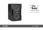
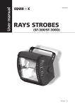
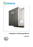
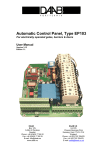
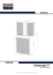
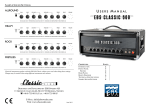
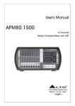
Technical Data • Charging Unit
2. Charging Unit
2.1 9A0100.11 UPS 24 VDC
Figure 2: UPS Charging Unit 9A0100.11
2.1.1 Technical Data
UPS 24 VDC
Input during Mains Operation
Rated Voltage Value
Voltage Range
9A0100.11
Regulated DC voltage
24 VDC
20 - 30 VDC at a switching threshold of 18 V 1)
23.5 - 30 VDC at a switching threshold of 21.5 V 1)
Output during Mains Operation
Rated Voltage Value
Voltage Range
Max. Output Current
24 VDC
20 - 30 VDC or 23.5 - 30 VDC depending on the set switching threshold 1)
8A
Output during Battery Operation
Switching Threshold Mains / Battery
Operation 1)
Rated Voltage Value
Voltage Range
Max. Output Current
Mains Failure Bridging
18 V at 20 - 30 VDC input
21,5 V at 23.5 - 30 VDC input
24 VDC
21 - 26,8 VDC (40 °C) or 28.2 VDC (0 °C)
8 A (load-side)
max. 20 minutes with 150 W load (with battery 9A0100.12, 24 V / 7.2 Ah)
Battery Charging Rating
Charging Clearing Voltage
Charging Current
27,6 VDC
Can be set from 0.88 A to 2.88 A
adjustable in 0.01 A increments, depending on type: using B&R Configuration Software and
HyperTerminal (0.5 - 2.88 A) or 0.25 A: using button (0.88 to 2.88 A)
Table 4: Technical Data 9A0100.11
18
Uninterruptible Power Supply User's Manual V 5.0
Technical Data • Charging Unit
UPS 24 VDC
Status Display
Operating Mode
Status
Battery Charging Current
Battery Status
Battery Reverse Polarity
Fuses
Interface
CTS (Clear To Send)
DCD (Data Carrier Detect)
DTR (Data Terminal Ready)
9A0100.11
Yes; depending on the set switching threshold: 21 V when 18 V 1) or 21.5 V when 21.5 V 1)
Yes
Yes; for mains supply, battery and battery charger 2)
Yes; for mains supply and battery
LED green (mains operation, battery operation, etc.)
LED yellow (overload, temperature alarm, etc.)
LED yellow (charging current strength)
LED yellow (battery change, age, etc.)
LED red (battery reverse polarity, not connected)
LED red (mains supply, battery, battery charger)
Serial, RS232
Signals power failure
Signals shutdown
Signals remote shutdown of the UPS
Standards
UL
Environmental Temperature
Operation
Storage
Transport
0 - 55 °C
- 20 °C to +60 °C
- 20 °C to +60 °C
Humidity
Operation
Storage
Transport
5 - 95 % (non-condensing)
5 - 95 % (non-condensing)
5 - 95 % (non-condensing)
Vibration
Operation
Storage
Transport
max. 9 - 200 Hz and 1 G (9.8 m/s² 0-peak)
max. 2 - 500 Hz and 4 G (39.2 m/s² 0-peak)
max. 2 - 500 Hz and 4 G (39.2 m/s² 0-peak)
Shock
Operation
Storage
Transport
max. 15 G (147 m/s² 0-peak) and 11 ms length
max. 100 G (980 m/s² 0-peak) and 6 ms length
max. 100 G (980 m/s² 0-peak) and 6 ms length
Software Support
Altitude
Dimensions (W x H x D)
Microsoft Windows 95 / 98 / ME / NT4.0 / 2000 / XP
Max. 3000 meters above sea level
185 x 115 x 69 mm (see also figure 3 "Dimensions 9A0100.11" on Page 20)
Weight
Mounting Instructions
Chapter 2
Technical Data
Protection and Monitoring
Deep Discharge Protection
Short-circuit Protection
Fuses
Reverse Polarity Protection
Approx. 1.2 kg
see Chapter 3 "Installation" on Page 41
Table 4: Technical Data 9A0100.11 (cont.)
1) Can be set using B&R UPS Configuration Software or HyperTerminal (18 or 21.5 VDC).
2) The charging unit fuse is not necessary with Revision L0 and higher.
Uninterruptible Power Supply User's Manual V 5.0
19
Technical Data • Charging Unit
2.1.2 Dimensions
168.4
69
154.4
35.8
ø 4.5
39.8
115
ø 10
184.5
Figure 3: Dimensions 9A0100.11
2.1.3 Contents of Delivery
The following components are included in the delivery of the B&R UPS 24 VDC :
Amount
Component
1
UPS Charging Unit
5
orange connection plug (plugged in)
Table 5: Delivery 9A0100.11
20
Uninterruptible Power Supply User's Manual V 5.0
Technical Data • Charging Unit
2.1.4 Device Interfaces
Power Connection
Load Connection
Chapter 2
Technical Data
Status-LEDs
User Button
Sicherungen
Serial Interface
Battery connection
Relay Connection
Ext. Button
Temperature Sensor Connection
Figure 4: Device Interfaces 9A0100.11
Power mains connection
24 V mains supply connection. Regulated DC voltage, rated voltage value 24 VDC, voltage
range according to the set switching threshold 1) when 18 V 20-30 VDC and when 21.5 V 23.5 30 VDC:
Power mains connection
Pin
Assignment
+
Input VDC +
-
Input VDC -
n.c.
Not connected
Ground connection
Table 6: Power mains connection
Correct pin assignments are also indicated on the UPS.
Warning!
Applying power over 30 VDC can damage the UPS! The UPS must be grounded
using the ground connection provided.
1) Can be set using B&R UPS Configuration Software or HyperTerminal (18 or 21.5 VDC).
Uninterruptible Power Supply User's Manual V 5.0
21
Technical Data • Charging Unit
Load Connection
Load connection (e.g. B&R IPC with 24 VDC bus unit).
Power mains connection
Pin
Assignment
+
Output VDC +
-
Output VDC -
n.c.
Not connected
Ground connection
Table 7: Load Connection
Correct pin assignments are also indicated on the UPS.
Warning!
The UPS must be connected with the load system ground connection, using the
ground connection provided.
For mains operation:
Rated voltage value 24 VDC, voltage range is dependent on the set switching threshold 1) 18 V:
20-30 VDC, 21.5 V: 23,5-30 VDC; maximum output current: 8 A
For battery operation:
Rated voltage value 24 VDC, voltage range 21 -26.8 VDC (40 °C) or 28.2 VDC (0 °C); maximum
output current: 8 A
1) Can be set using B&R UPS Configuration Software or HyperTerminal (18 or 21.5 VDC).
22
Uninterruptible Power Supply User's Manual V 5.0
Technical Data • Charging Unit
Fuses
The two replaceable fuses on the front side of the device protect the power mains input and
the battery connection from over-current, reverse polarity (using a diode which is controlled by
the firmware to make a connection when the polarity is correct) and short circuits (using a fuse
and firmware).
Type:
Glass tube fuses 5 x 20 mm:
T 10 A / 250 V
Network
10 A / 250 V
Chapter 2
Technical Data
Fuses
Mains
T10A/250V
T10A/250V
Battery
10 A / 250 V
Battery
Table 8: Fuses
Battery Connection
The battery units are connected using the cable included in delivery, using the red (+) and
black (-) leads of the battery cable.
Battery Connection
Pin
Assignment
n.c.
Not connected
+
Battery + Pin
-
Battery - Pin
n.c.
Not connected
Table 9: Battery Connection
Correct pin assignments are also indicated on the UPS.
Warning!
Disconnecting the battery and reconnecting it with reversed polarity within one
minute can damage the UPS!
Relay Output
A power failure is also signalled immediately by the UPS by setting a relay output. An external
electrical circuit can be switched (closed or opened) using the relay output.
Uninterruptible Power Supply User's Manual V 5.0
23
Technical Data • Charging Unit
Relay output
Pin
Assignment
n.c.
Not connected
Relay output
Table 10: Relay output
For relay output contact data, see Section "Relay Output", on Page 115.
External Button, Temperature Sensor Connection
The temperature sensor for the battery unit is connected using the supplied cable. Both of
the battery cable's white leads are to be used for this.
Ext. Button, Temperature Sensor Connection
Pin
Assignment
Button +
Positive edge input
Button -
Negative edge input
Temp.
Temperature sensor
Temp.
Temperature sensor
Button+
Button–
Temp.
Temp.
Table 11: Ext. Button, Temperature Sensor Connection
See Section "ExternalButton User Button (Digital Input) and DIB (Digital Input Button)", on
Page 109 for connecting an external button..
24
Uninterruptible Power Supply User's Manual V 5.0
Technical Data • Charging Unit
RS232 interface
The UPS communicates with the load system (e.g. B&R IPC) via the serial interface.
RS232 interface
Pin
Assignment
1
DCD
2
RXD
TxD
4
DTR
5
GND
6
DSR
7
RTS
8
CTS
9
n.c.
9-pin DSUB plug
Chapter 2
Technical Data
3
Table 12: RS232 interface
The 7 pin null modem cable required for this must have two 9 pin DSUB sockets (female).
The appropriate cable can be ordered directly from B&R under the model number 9A0017.01
(length = 0.6 m) and 9A0017.02 (length = 1.8 m).
The cable can also be made. A self made cable can have a maximum length of 15 meters.
The pins must be connected as follows:
Load System
DSUB Socket
Pin
UPS
DSUB Socket
Pin
4
DTR
(Data Terminal Ready)
2
3
TxD
(Transmit Data)
3
2
RxD
(Receive Data)
1
DCD
(Data Carrier Detect)
6
DSR
(Data Set Ready)
DCD
(Data Carrier Detect)
1
DSR
(Data Set Ready)
6
RxD
(Receive Data)
TxD
(Transmit Data)
DTR
(Data Terminal Ready)
Signal Direction
4
Ground
5
5
Ground
RTS
(Request to Send)
7
8
CTS
(Clear to Send)
CTS
(Clear to Send)
8
7
RTS
(Request to Send)
UPS Function
Alerts of
Shutdown
Alerts of UPS
Remote Shutdown
Alerts of
Power Failure
Figure 5: Pin assignment RS232 cable
User Button
See Section "ExternalButton User Button (Digital Input) and DIB (Digital Input Button)", on
Page 109 for possible uses of the user button.
Uninterruptible Power Supply User's Manual V 5.0
25
Technical Data • Charging Unit
Status LEDs
The UPS has six status LEDs that show the operating state, indicate any faults or display
information about the battery units. The LEDs are also used to manually set the charging current
for the battery unit via the user button (see Section "Setting the Maximum Charging Current", on
Page 118). Each LED can display several different types of information based on flashing
sequence:
Figure 6: Status LEDs
Function
Operation
Color
Green
LED Number
Flashing sequences /
Interval:
0.125 s = 8 Hz
ON
OFF
Mains operation OK
ON
OFF
Mains operation with no battery
ON
OFF
Battery operation
ON
OFF
Shut Down
0
Status
0.5
1
Seconds
ON
OFF
UPS self-test
ON
OFF
Overload
ON
OFF
Yellow
Internal error
ON
OFF
Temperature alarm
ON
OFF
Battery capacity too low
0
0.5
1
Seconds
1)
Fuses
Red
ON
OFF
Error: 24 V-mains fuse, or mains voltage < 20 V or
23.5 V (depending on the switching threshold 18 or 21,5V)
ON
OFF
Error: 24 V-battery fuse
ON
OFF
Error: internal fuse
0
Battery
Reverse
Polarity
0.5
Seconds
1
ON
OFF
Red
Battery polarity is reversed
ON
OFF
No battery attached
0
0.5
1
Seconds
Table 13: LED Status - Flashing Sequences and their Meaning
26
Uninterruptible Power Supply User's Manual V 5.0
Technical Data • Charging Unit
Battery
Status
Color
LED Number
Flashing sequences /
Interval:
Change battery (battery malfunctioned
or did not pass capacity test)
ON
OFF
Yellow
ON
OFF
0
Battery
Charging
0.125 s = 8 Hz
Yellow
0.5
1
Seconds
Battery lifespan exceeded (dependant on type) or
low battery capacity
ON
OFF
Maximum Charging Current = max. Charging Current
ON
OFF
Medium Charging Current = 30 - 60 % of max. Charging C
ON
OFF
Chapter 2
Technical Data
Function
Low Charging Current = 0 - 30 % of max. Charging Curren
0
0.5
1
Seconds
Table 13: LED Status - Flashing Sequences and their Meaning
1) A reliable detection of a defective fuse is guaranteed only if the supply voltage is in the specified range according to the operating mode
(switching threshold mains/battery).
Uninterruptible Power Supply User's Manual V 5.0
27