1
AT1000 User Manual
V1.2
Contents
1.
INTRODUCTION...............................................................................................................3
ATTENTION ........................................................................................................................................................3
INSTRUCTIONS OF SAFETY ................................................................................................................................4
LEGAL NOTICE ..................................................................................................................................................4
ABOUT DOCUMENT ...........................................................................................................................................5
BATTERIES ..........................................................................................................................................................5
PACKAGE CONTENTS ........................................................................................................................................5
2.
CHARACTERISTICS...........................................................................................................6
BASIC CHARACTERISTICS...................................................................................................................................6
MECHANICAL CHARACTERISTICS .....................................................................................................................6
SIM CARD INSERT SCHEME ...............................................................................................................................7
CONNECTING MICRO USB TO AT1000 ..........................................................................................................7
ELECTRICAL CHARACTERISTICS .......................................................................................................................8
ACCESSORIES ......................................................................................................................................................8
3.
PREPARATION...................................................................................................................9
SOFTWARE REQUIREMENTS..............................................................................................................................9
DRIVERS ..............................................................................................................................................................9
CONFIGURATOR ...............................................................................................................................................11
INSERTING THE BATTERIES ............................................................................................................................12
4.
OPERATIONAL BASICS .................................................................................................. 14
PROFILES ...........................................................................................................................................................14
EVENTS .............................................................................................................................................................15
5.
CONFIGURATION........................................................................................................... 16
OPERATIONS MENU .........................................................................................................................................16
GLOBAL PARAMETERS ....................................................................................................................................17
GPRS settings.................................................................................................................................................17
GPS fix settings ..............................................................................................................................................17
SMS settings ...................................................................................................................................................17
General settings................................................................................................................................................18
PROFILES PARAMETERS ...................................................................................................................................22
Sleep................................................................................................................................................................23
Data save ........................................................................................................................................................23
Data send........................................................................................................................................................24
BATTERY SETTINGS .........................................................................................................................................24
DEFAULT SETTINGS .........................................................................................................................................24
Scenario #1 ....................................................................................................................................................24
Scenario #2 ....................................................................................................................................................25
Scenario #3 ....................................................................................................................................................25
I/O SETTINGS...................................................................................................................................................25
6.
SMS COMMAND LIST...................................................................................................... 26
GETVER..............................................................................................................................................................26
GETSTATUS........................................................................................................................................................27
GETINFO............................................................................................................................................................27
GETOPS ..............................................................................................................................................................27
GETGPS ..............................................................................................................................................................28
1
7.
UPDATING FIRMWARE TO THE LATEST VERSION............................................... 29
8.
MOUNTING RECOMMENDATIONS ........................................................................... 30
9.
CHANGES LOG................................................................................................................. 31
2
1. INTRODUCTION
AT1000 is a terminal with GPS and GSM connectivity, which is able to determine the object’s
coordinates and transfer them via the GSM network. This device is perfectly suitable for applications
where location acquirement of remote objects is needed. Device operates using internal batteries only
and its main applications are tracking of objects which do not have onboard power supply.
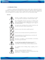
Attention
Personal or portable computers to be connected to the device
must comply with the requirements of DIN EN 60950-1.2003.
Do not disassemble the device more than it is allowed. If the
device is damaged, the power supply cables are not isolated or
the isolation is damaged, before unplugging the power supply, do
not touch the device.
All wireless data transferring devices produce interference that
may affect other devices which are placed nearby.
The device may be fitted only by qualified personnel.
The device must be firmly fastened in the predefined location.
The programming must be performed using a second class PC
(with autonomic power supply).
The device is susceptible to water and humidity in environment
with IP class greater than IP65.
Use only batteries provided by Teltonika. If wrong battery is
used, the device may malfunction. Teltonika takes no
responsibility for device damage caused by third party batteries.
Any installation and/or handling during a lightning storm is
prohibited.
Please use cables provided with AT1000 device.
Teltonika is not responsible for any harm caused by using wrong
cables for PC <-> AT1000 connection.
3
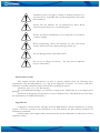
Teltonika reserves the right to change or modify the device in a
way that feels is acceptable and is not in disagreement with terms
and conditions.
Ensure that the batteries are not immersed in water. When
stored, keep the device in a cool and dry place.
Ensure that device and batteries are not exposed to hot surfaces
or direct sunlight.
When transporting, ensure that batteries are safe from metal
articles and do not keep it with metal rings, chains, etc.
Do not damage battery with sharp objects.
Do not try to charge the battery – this may lead to explosion
and/or other harms.
Instructions of safety
This chapter contains information on how to operate AT1000 safely. By following these
requirements and recommendations, you will avoid dangerous situations. You must read these
instructions carefully and follow them strictly before operating the device!
The device uses a 5V...7.2V DC batteries.
To avoid mechanical damage, it is advised to transport the AT1000 device in an impact-proof
package.
The device is designed to be mounted in a zone of limited access. All related devices must meet
the requirements of standard EN 60950-1.
Legal Notice
Copyright © 2010 Teltonika. All rights reserved. Reproduction, transfer, distribution or storage
of part or all of the contents in this document in any form without the prior written permission of
Teltonika is prohibited.
Other products and company names mentioned here may be trademarks or trade names of their
respective owners.
4
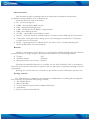
About document
This document contains information about the architecture, mechanical characteristics,
configuration and possibilities of the AT1000 device.
Acronyms and terms used in document
PC – Personal Computer.
GPRS – General Packet Radio Service.
GPS – Global Positioning System.
GSM – Global System for Mobile Communications.
SMS – Short Message Service.
AC/DC – Alternating Current/Direct Current. (check out new album Black Ice!)
Record – AVL data stored in AT1000 memory. AVL data contains GPS and I/O information
AVL packet - Data packet that is being sent to server during data transmission. AVL packet
contains from 1 to 25 records.
Profile – operating mode for AT1000 device. It consists of list of settings indicating how
device should behave in certain situations.
Batteries
AT1000 is autonomous device which uses two R14 (IEC 60086 standard) batteries. Batteries
used in this device are single charge Li based type and should have the following parameters:
Voltage:
3.6V
Nominal capacity:
5500mAh
Max pulse current not less than: 2000mA
Teltonika recommended batteries are available for sale from Teltonika office or distributors .
Only with these batteries correct device operation and (or) prevention of permanent damage to device
is guaranteed.
Warning: use only the same sort of batteries in pair and do not mix old batteries with new ones.
Package contents
The AT1000 device is supplied to the customer in a cardboard box containing all the equipment
that is necessary for operation. The package contains:
1. The AT1000 device.
2. Micro USB cable.
3. 2 x 3.6V batteries (optional with 4 additional batteries)
4. A disclaimer
5. Driver/softaware download link
5
2. CHARACTERISTICS
Basic characteristics
GSM / GPRS features:
Teltonika TM1Q quad band module (850, 900, 1800, 1900 MHz)
GPRS class 10
SMS (text, data)
GPS features:
No less than 20 channel receiver
No less than -160 dBm sensitivity
Special features:
Smart profile switching (any element dependant)
Highly configurable data acquisition and sending
Multiple geofence areas
Real-time process monitoring
Authorized number list for remote access
Firmware update via GPRS or USB
Configuration update via GPRS or USB port
TCP/IP or UDP/IP protocol support
7500 record storing
Extra long lifetime
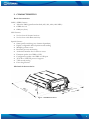
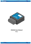
Mechanical characteristics
Figure 1. AT1000 dimensions
6
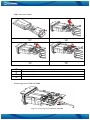
SIM card insert scheme
Figure 2. SIM card insert scheme
Open AT1000 device
Open SIM card lid and insert the SIM card
Close SIM card lid
Push SIM card lid in the shown direction to lock it and assemble AT1000
Connecting micro USB to AT1000
Figure 3. Connecting micro USB cable to AT1000
7
Electrical characteristics
AT1000:
Power supply: 5...7.6V DC
Operation temperature: -20C ... +60C
Batteries:
Voltage:
Nominal capacity
Max pulse current not less than
3.6V
5500mAh
2000mA
The lifetime of AT1000 is subject to configuration and coverage of GPS and GSM signals.
According to recommended default configuration expected lifetimes:
6 months - GPS acquire every 1 hour and data sending every 24 hour.
25 days - GPS acquire every 20 minutes and data sending every 1 hour.
Expected battery lifetime depends on:
Temperature;
Humidity;
GSM level
GPS satellite visibility
Configuration of device – additionally monitored parameters, etc.
Expected battery self discharging is 1-3% per year in normal humidity and 20°C. .
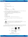
Accessories
Note: Teltonika doesn’t provide any additional equipment like panic
Buttons or other, except of 1 – wire digital thermometer. This device is not included
in AT1000 package and can be offered by special order only.
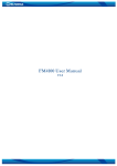
Digital thermometer
There is a possibility to monitor temperature via AT1000. In order to achieve such functionality
digital thermometer has to be connected to device input. AT1000 supports 1-Wire Parasite-Power
digital thermometer (DS18B20-PAR). Figure 4 shows thermometer connection scheme.
Figure 4. AT1000 and Dallas sensor connection
8
3. PREPARATION
Software requirements
Windows XP with SP2 or later, Windows Vista, Windows 7
MS .NET Framework V3.5 or later (http://www.microsoft.com or
http://avl1.teltonika.lt/downloads/tavl/Framework/dotnetfx35setupSP1.zip).
Drivers
Please
download
Virtual
COM
Port
drivers
from
http://avl1.teltonika.lt/Downloads/AT1000/vcpdriver_v1.1_setup.zip.
Teltonika
website:
IMPORTANT: AT1000 must be connected to PC when installing drivers.
Power up AT1000 and connect it to PC. It is done by removing insulating tape, which is
separating batteries from the device.
Figure 5. Removing insulating tape in AT1000
9
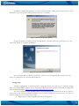
When AT1000 is connected for the first time to PC, you will be prompted with 'Found New
Hardware' window. Click 'Cancel' to stop automatic installation process.
Figure 6. Found New Hardware window
Extract and launch VCPDriver_V1.1_Setup.exe. This driver is used to detect AT1000 device
connected to the computer. Click 'Next' in driver installation window.
Figure 7. Driver installation window
10
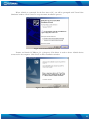
Installation wizard will prompt you with several windows telling that software did not pass
Windows Logo test. Click 'Continue Anyway' button to continue.
Figure 8. Windows Logo pass window
Setup will continue installing drivers and will display a window about successful process in the
end. Click 'Finish' to complete installation.
Figure 9. Successful installation window
Note: if drivers did not install successfully or device is not recognized, please make sure that
device is connected to PC and reinstall the drivers.
Configurator
AT1000 Configurator is software used to setup the device. You can save or read the settings
and read modem IMEI number with it. Please download the latest version of AT1000 Configurator
from Teltonika webpage: http://avl1.teltonika.lt/Downloads/AT1000.
To use Configurator with AT1000, make sure that batteries are inserted in the device and it is
connected to PC. In the configurator please choose correct COM port used by device. To find out
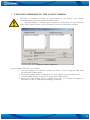
which COM port is used follow these steps:
Right-click on 'My Computer' and choose 'Properties';
11
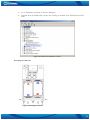
Go to 'Hardware' and click on 'Device Manager';
Expand 'Ports (COM & LPT)' menu. See COM port number near 'STM Virtual COM
Port'.
Figure 10. STM Virtual COM Port number
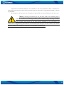
Inserting the batteries
Figure 11. Inserting the batteries
12
Teltonika recommended batteries are available for sale from Teltonika office or distributors.
Only with these batteries correct device operation and (or) prevention of permanent damage to device
is guaranteed.
Warning: use only the same sort of batteries in pair and do not mix old batteries with new ones.
Note: if inserting the batteries for the first time, make sure insulating tape is
removed! In order not to discharge batteries, please remove them if not using the device.
After inserting new batteries to the device, please remember to reset the battery level
counter in the configurator. If new batteries are not inserted, do not try to reset this counter (more details
about the battery level counter are described in user manual documentation).
13
4. OPERATIONAL BASICS
Profiles
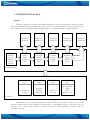
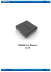
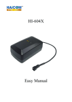
In order to preserve the battery, AT1000 is designed to stay in a sleep mode as long as possible.
Device periodically (each 2 seconds) wakes up for a very short time and checks states of IO events. If
IO event(s) state has changed, profile manager changes to profile according to logical sentences.
START
checking
logical
sentences
every 2
seconds
Switch to
profile #1
Switch to
profile #2
Switch to
profile #3
Switch to
profile #4
Yes
Yes
Yes
Yes
Is first
logical
sentence
true?
Is second
logical
sentence
true?
Is third
logical
sentence
true?
Is fourth
logical
sentence
true?
No
No
No
Switch to
profile #5
No
Profile manager
1st Profile
logic
2nd Profile
logic
Low battery
voltage
Entered
roaming
network
3rd Profile
logic
4th Profile
logic
Device is
moving
Door opened
AND
not in
geofence zone
IO events
Figure 12. Profile switching diagram.
After device reset or startup, AT1000 always loads profile #1 as default. In the next 10 second
period it checks all IO event conditions and switches to appropriate profile in case there are any
events. If no – then device switches to profile #5 which is default profile for device when no
conditions are met.
14
See profile manager configuration chapter for more information about logical sentence
structure.
Events
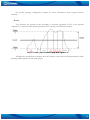
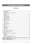
I/O elements can generate events according to hysteresis algorithm. If I/O event operand
“Hysteresis” is selected, events will be generated as it is shown in the illustration below:
Figure 13. Event generation according hysteresis algorithm
AT1000 uses this method to calculate those IO element events that have Delta parameters: GPS
speeding, GSM signal level and Analog input.
15
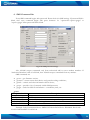
5. CONFIGURATION
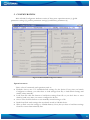
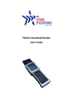
Main AT1000 Configurator windows consist of three parts: operations menu (1), global
parameters settings (2), profiles parameters settings(3) and battery parameters (4).
Figure 14. Main AT1000 Configurator window
Operations menu
This is a list of commonly used operations such as:
Defaults: choose one of 3 available default settings for the device. Every time you launch
Configurator software, you either have to load settings from file, or load default settings and
modify values manually.
Load from file: click this button to load device settings from file so you don't have to enter
them by hand every time you want to configure the device.
Save to File: click this button to save manually entered setting to a file.
Read from flash: reads settings that are already stored in AT1000 device.
Write to flash: saves the settings to AT1000 memory. Note, that you have to load these settings
from file or enter them manually first.
16
Get IMEI: reads AT1000 modem IMEI (International Mobile Equipment Identity) number.
Note, that after you connect device to power supply, it takes several seconds to load modem –
only then Configurator is able to read it. Otherwise it will be displayed as 'none'.
Device startup: click this button to test data acquisition and data sending. This feature initiates
position acquisition from the GPS satellites. After coordinates are received, data is sent to
server as defined in global parameters.
COM port: click this drop-down list to choose which COM port is used by AT1000 to connect
to PC. See chapter 0 to find out number of the port.
Refresh button: click it to refresh all available ports on PC. This button is used when you
connect AT1000 to PC while Configurator software is already launched, but it did not detect
Virtual COM Port yet.
Global Parameters
Global parameters are common settings for device and are used with every profile. These are
GPRS settings, GPS fix settings, SMS settings and general settings.
GPRS settings
Mode: select data transfer mode for GPRS connection – TCP/IP or UDP/IP;
APN: (Access Point Name) this is operator provided parameter and is used to open GPRS
connection in GSM network. Please contact your GSM operator to find out your APN.
Username: APN username used to open GPRS connection in GSM network. In some cases it
is not required and field is left blank.
Password: APN password used to open GPRS connection in GSM network. In some cases it
is not required and field is left blank.
IP: this is destination server IP address to which AT1000 is sending data using GPRS.
Port: this is destination server port number to which AT1000 is sending data using GPRS.
GPS fix settings
Timeout: AT1000 is using this time interval (in seconds) when trying to establish its location. If
it fails to do so in given time, device considers that GPS is not available at the moment.
SMS settings
Password: enter a password for all incoming SMS to the device. Device will discard all recieved
SMS with passwords that do not match the entered one.
Authorized numbers: a list of GSM numbers – AT1000 will read messages only from listed
number and discard all messages from other numbers. If no numbers are entered, AT1000 will
read messages from all numbers. The first number is server GSM number – it is used to send
SMS to server modem. Numbers have to be entered in international format without '+' sign.
17
Figure 15. Authorized numbers window
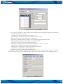
General settings
Movement sensor: these parameters combined with onboard vibration sensor are used to
define if device is moving. While measuring (during Scan time) device captures Vibration
Count, after the end decision is done accord to equation (Scan Time / Average Time to
Impulses) ≤ Vibration Count. If equation is true, then device is considered as moving.
Figure 16. Movement sensor settings window
Figure 17. Movement sensor measurement diagram
Geofence zones: these parameters allows to know if device is in certain area or not.
Geofencing Frame border is measured in meters. Zone Border feature is specially used in order
to specify certain region within which crossing will not be indicated as event until border is cmpletely
crossed (hysteresis-like principle).
18
Figure 18. Geofence border working principle (1)
Figure 19. Geofence border working principle (2)
Geofence Shape: Individual Geofencing Zone shape selection. There are two shapes available:
Circular or Rectangular.
Geofence Event Priority: Reserved for future uses, leave 0.
Geofence Enter Event: Individual Geofencing Zone Entering event generation functionality. If
enabled – when device enters specified area, an event of selected priority will be generated.
Geofence Exit Event: Individual Geofencing Zone Exiting event generation functionality. If
enabled – when Device exits specified area, an event of selected priority will be generated.
Geofence Center Longitude (X, degrees) / Geofence Left Bottom Corner Longitude (X1,
degrees): Individual Geofencing Zone Center Longitude coordinate for Circular shape or Left Bottom
Corner Longitude coordinate for Rectangular shape.
Geofence Center Latitude (Y, degrees) / Geofence Left Bottom Corner Latitude (Y1, degrees):
Individual Geofencing Zone Center Latitude coordinate for Circular shape or Left Bottom Corner
Latitude coordinate for Rectangular shape.
Geofence Radius (R, meters) / Geofence Upper Right Corner Longitude (X2, degrees):
Individual Geofencing Zone Radius measured in meters for Circular shape or Upper Right Corner
Longitude coordinate for Rectangular shape.
Not Used / Geofence Upper Right Corner Latitude (Y2, degrees): Individual Geofencing Zone
Right Corner Latitude for Rectangular shape. Not used for Circular shaped zone.
19
Figure 20. Geofence settings window
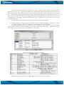
IO events: according to these settings device will respond changing circumstances and include
certain information to records.
Low Battery: information that device battery is low.
Critical Battery: information that device battery is critically low.
Roaming: information that device is in roaming state.
GPS timeout: information that GPS fix is not obtained within predefined time.
GPS speeding: information about device movement speed.
GSM level: information about GSM signal strength.
Land/water map: information about whether device is on water or on land.
Temperature*: temperature measurement information.
Analog input*: analog input voltage measurement information.
Alarm button*: alarm button state information.
Cell ID: information about GSM cell ID number.
*
- Temperature sensor, Analog input and Alarm button shares the same hardware so only one feature
can be used at the time. More information about IO events can be found in Profile manager section.
Figure 21. IO events window
20
Level field and delta indicate a value level – when it exits or enters value +- delta/2, device
generates an event. I.e. to generate speeding event when speed reaches 80 km/h enter level value 40
and delta value 80. This would make low level of speed 0 km/h (40 – 80/2) and high level 80 km/h
(40 + 80/2). When current speed exits this range, event will be triggered. As alternative you can also
enter level 90 and delta 20. This would trigger event when speed becomes 80...100 km/h. Battery level
is measured in percentage, speeding measured in km/h, GSM level is measured in point with
maximum value of 5.
Average field is not currently in use and is reserved for future functionality.
Profile manager: managing between profiles is done via Profile Manager. Basically it is done
via logical sentences, which are collection of criteria encoded in 50 characters.
If external circumstances are identical to those stated in logical sentence, profile switching
occurs. There are four sentences: getting from first to fourth profile. Switching to fifth profile occurs
when there are no valid sentences which matches to IO events.
Figure 22. Profile manager window
Table 1. Legend of logical sentence parameters
Example of good logical sentence: MR1=0&{{CI1=1|GT1=0}^AI1<3000}
21
Incorrect string elements of logical sentence: {} }{ {* *} and double operators !=, where *
represents table 2 operators excluding { and }.
Table 2. Operators used in logical sentences
Operator Operation
=
Equal
!
Not equal
>
More
<
Less
&
AND
|
OR
^
XOR
{
Matching to }
}
Matching to {
Valid GPRS operator list: contains list of up to 200 accepted operator codes. Only in these
operators network data can be sent. If operator list left empty, GPRS is available with all
operators available. List of GSM operator codes:
http://en.wikipedia.org/wiki/Mobile_Network_Code
Figure 23. Valid GPRS operator list window
Profiles parameters
This set of parameters applies for device only when it is operating in appropriate profile. To
choose a profile click on 'P1', 'P2', 'P3', 'P4' or 'P5' and enter desired values. Refer to profile switching
logic chapter to find out correct settings for your AT1000 device.
22
Figure 24. Profile selection in Configurator window
Sleep
Indicates what to do with the modem when device is not sending any data – either to keep it
online or switch it off to save battery (highly recommended in most cases).
Data save
GPS enable: enables or disables GPS data acquisition in this profile.
GSM Cell ID: enables or disables ability to acquire GSM Cell ID
Min. Period: time interval in seconds, when device is trying to establish its location and make a
record.
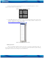
Save week time: if 'Min. Period' value is 0, then AT1000 uses this table when to make records.
You can set the time in 10 minute intervals and choose weekdays to do it.
Figure 25. Save week time table
23
Data send
GPRS enable: enables or disables GPRS in this profile
Send Period: time interval in seconds, when device is trying to send recorded data to the
server.
Send week time: if 'Send Period' value is 0, then AT1000 uses this table to send records. You
can set the time in 10 minute intervals and choose weekdays to do it. The table is same as for
data recording ('Save week time' table).
Min. Saved Records: every time AT1000 makes attempt to connect to the server, it checks if it
has at least predefined number of records to send. If it has less records than the value of this
field, it does not connect to the server and waits for next attempt after time, entered in 'Send
Period' field or 'Send week time' table. If it has enough records, device connects to the server
and sends them.
SMS 24 enable: enables ability to send data as binary SMS containing max 24 records.
Destination modem number is entered in 'Authorized numbers' table, 'SMS settings' under
'Global parameters' menu. AT1000 uses this method when it is not allowed to connect to
server using GPRS due to operators listed in the 'GSM Operators' table.
Note: since AT1000 is designed to stay in sleep mode to preserve the battery, it establishes new
GPS connection every time it wakes up which takes some time. Acquire and send intervals may have a
small delay if 'Save Week Time' table or 'Send Week Time' tables are used.
Battery Settings
AT1000 is able to monitor battery usage as percentage using internal counter. When new
batteries are inserted, click 'Reset Counter' button to start calculating battery level from the beginning.
Do not reset the battery level counter if not inserting new batteries! Click 'Refresh Data' button
to see current battery level.
Default settings
AT1000 has 3 preconfigured templates for 3 different tracking scenarios: tracking mobile
objects, tracking international objects and tracking shipping containers. Only essential values are
present, since server IP, geofence zones and some other settings are subject to individual configuration
for every case.
Scenario #1
Designed for mobile objects security:
While moving collect data every 20 minutes, send data every 1 hour;
While idle collect and send data every 24 hours;
If geofence zone crossed: collect data every 5 minutes and GSM modem is always online.
Expected battery lifetime is 3 months if object moves about 8 hours a day with no alarm
captured. Configuration for this scenario is hardcoded into default profile #1.
24
Scenario #2
Designed for customs/shipment transit tracking:
While moving collect data every 1 hour, send data every 12 hours;
While idle collect and send data every 24 hours;
If geofence zone crossed: collect data every 5 minutes and GSM modem always online.
Expected battery lifetime is 6 months with no alarm captured. Configuration for this scenario is
hardcoded into default profile #2.
Scenario #3
Designed for shipping containers tracking:
While moving collect data every 1 hour, send data every 12 hours;
While idle collect and send data every 24 hours;
If object distance from coastline more than 30km, do not enable GSM modem;
When container doors are open, collect data every 5 minutes and GSM modem always online
if object is distanced less than 30km from coastline;
If device is unable to get GPS fix, but under GSM coverage, records GSM Cell ID;
If geofence zone crossed, collect data every 5 minutes and GSM always online.
Expected battery lifetime is more than 6 months with no alarm captured. Configuration for this
scenario is hardcoded into default profile #3.
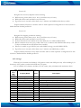
I/O settings
When all I/O elements are disabled, AVL packet comes with GPS part only. After enabling I/O
element(s) AVL packet contains both GPS and I/O parts.
List of available I/O elements includes I/O id, names, units, minimum and maximum values.
Table 3. Property ID of I/O elements.
Property
ID in
Property Name
Bytes
AVL
packet
1
Battery level
2
9
Analog Input
2
21
GSM Signal Strength
1
22
Current profile
1
53
Alarm button
1
72
Temperature sensor
2
101
Critical Battery
1
102
Land Water Map
1
103
Battery Resistance
2
200
Cell ID
2
210
GpsSpeed
2
238
GPS Timeout
1
239
Roaming Mode
1
240
Movement sensor
1
Description
0-100 %
0 – 3300 mV
Signal strength level 0 (lowest) – 5 (highest)
Profile Number 1-5
0 - OFF; 1 - ON
O
10*Degrees ( C)
0 - normal state; 1 - critical batery state
0-water; 1-land
Battery Resistance in Ohms
GSM Operator Cell ID
km/h
0 - not in timeout; 1 - GPS timout reached trying to get fix
0 - not in Roaming mode; 1 - in Roaming mode
0 - not moving; 1 - moving
25
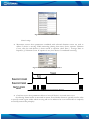
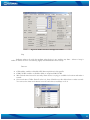
6. SMS Command list
Every SMS command begins with password. Please check it in SMS settings. If password field is
blank, then every command begins with space character. I.e. '<password><space>getgps' or
'<space>getgps' when password field is blank.
Figure 26. SMS password settings
Also AT1000 accepts commands only from authorized and/or server modem numbers. If
'Authorized Numbers' table is left blank, then AT1000 accepts commands from any number.
SMS commands are:
getver – gets firmware version;
getstatus – current status about device and general working conditions;
getinfo – statistic and other information about device;
getops – provides a list of currently visible GSM operators;
getgps – sends last GPS fix information – coordinates, time, etc.
getver
Response details
Code Ver
Device IMEI
Device ID
Bootloader Ver
Modem REV Ver
Description
Firmware version
IMEI
Device ID is used to detect which type of configuration to load
Version of modem application
Modem Firmware version
Example: Code Ver:00.00.29 Device IMEI:353976010139156 Device ID:000001 Bootloader
Ver:03.13 Modem REV Ver:05.95.00
26
getstatus
Response details
Data Link
GPRS
Phone
SIM
OP
Bat
Signal
Service
NewSMS
Roaming
SMSFull
Description
Indicate module connection to server at the moment: 0 – Not connected, 1
– connected
Indicate if GPRS is available at the moment
Voice Call status: 0 – ready, 1 – unavailable, 2 – unknown, 3 – ringing, 4 –
call in progress, 5 – asleep
SIM Status: 0-ready, 1-pin, 2-puk, 3-pin2, 4-puk2
Connected to GSM Operator: Numerical id of operator
Battery charge level [0-5] (not used)
GSM Signal Quality [0-5]
GSM service availability (0 – unavailable, 1 – available)
Indicate if new message received
0 – Home Network, 1 – roaming
SMS storage is full? 0 – ok, 1 – SMS storage full
Example: Data Link: 0 GPRS: 1 Phone: 0 SIM: 0 OP: 24602 Bat: 4 Signal: 5 Service: 1
NewSMS: 0 Roaming: 0 SMSFull: 0
getinfo
Response details
INI
RTC
RST
ERR
SR
BR
CF
FG
FL
UT
SMS
SAT
CP
PB0
PB
PD#
Description
Device Initialization Time
RTC Time
Restart Counter
Error Counter
Number of Sent Records
Number of broken records
Profile CRC Fail counter
Failed GPRS counter
Failed link counter
UPD Timeout counter
Sent SMS Counter
Average satellites
Current profile
Profile0 loads counter
Number of profile loads/changes
Profile# loads counter
Example: INI:2007/8/24 10:15 RTC:2007/8/24 12:43 RST:2 ERR:11 SR:182 BR:0 CF:0 FG:0
FL:0 UT:0 SMS:2 SAT:5 CP:5 PB0:0 PB:1 PD0:0 PD1:1 PD2:0 PD3:0 PD4:0 PD5:0
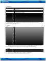
getops
Response details
LIST
Description
Returns list of current available allowed operators.
Example: (2,”LT BITE GSM”,”BITE”,”24602”),(3,”OMNITEL
LT”,”OMT”,”24601”),(3,”TELE2”,”TELE2”,”24603”),,(0-4),(0-2)
27
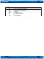
getgps
Response details
Sat
Lat
Long
Alt
Speed
Dir
Date
Time
Description
Count of currently available satellites
Latitude (Last good Latitude)
Longitude (Last good Longitude)
Altitude, m
Ground speed, km/h
Ground direction, degrees
Current date
Current GMT time
Example: Sat:7 Lat:54.71473 Long:25.30304 Alt:147 Speed:0 Dir:77 Date: 2007/8/24 Time:
13:4:36
28
7. UPDATING FIRMWARE TO THE LATEST VERSION
Teltonika is constantly working on improvement of the devices, and strongly
recommends using the latest versions of the firmware.
AT1000 Updater is software used to update the device with the latest firmware
(FW) version. Please contact your local vendor for the latest FW version available.
Figure 27. Updater application
Steps to update FW version successfully:
1. Insert the batteries into AT1000. Connect the device to the PC using the USB cable
provided with AT1000 device.
2. Launch the Updater. Select COM port that is using AT1000. Press Connect button.
3. After the IMEI and FW version are detected, press Update button.
4. Please wait while loading FW to AT1000 device. Do not interupt the update or
disconnect the device until the FW updating is complete!
29
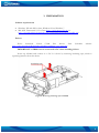
8. MOUNTING RECOMMENDATIONS
Attach AT1000 to a surface in a vertical position with GPS antenna facing upper part of case.
Make sure device gets as much of clear view of the sky as possible. Use screws or plastic tie strap
fasteners to tighten it.
30
9. CHANGES LOG
Nr.
1
2
3
Date
100323
100514
100826
New version No.
1.0
1.1
1.2
Comments
First release
Minor changes applied and screenshots updated
Accessories description added
31