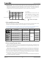
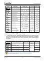
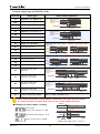
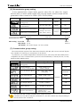
1
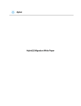
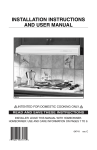
MICROCOMPUTER Digital PID Controller User’s Manual T50-SERIES T50 User’s Manual Preface Thank you for purchasing the T50 series from TemcoLine. The T50 series is a precision industrial controller that uses an advanced 2 degree-of-freedom (DOF) algorithm. The T50 series consists of 5 models, which are T52, T53, T54, T57, and T59. This manual explains the installation, the functions, the operation, and the handling of the products. Please read the manual thoroughly before using the products. If any difficulties arise while using our products, please call our customer service at 1588-5439. Pay attention to the followings! ▪ Use the products under the conditions specified in this manual. ▪ Please heed the cautions and warnings listed in this manual. ▪ The contents of the manual may be changed without notice. ▪ The product is designed to be used installed on a control panel. ▪ This manual is copyrighted, and may not be copied in part or in whole without permission. ▪ The manufacturer takes no responsibility for direct or indirect damages caused by careless operation or operation under unpredictable or risky environments. Safety requirements! Safety requirements are intended to prevent accidents and dangers through the proper use of the products, so please heed them at all times. The safety requirements are divided into “cautions” and “warnings”, which indicate the following. WARNING Serious injury or death may be caused if instructions are not observed. CAUTION Failure to observe these instructions may cause damage to the instrument or some injury to the user. REV 1.27 2 www.temcoline.net T50 User’s Manual WARNING 1. Use a separate safety device when this product is used to control a device that could harm lives or expensive property in the event of a malfunction or a breakdown. (This may cause fires, deaths, or damage to property) 2. Do not use this controller at place where there are flammable or explosive gas. (It may cause a fire or explosion.) 3. Before turning the power on, please check that wiring is correct to the number of terminal. (It may cause a fire) 4. Turn off the power during wiring and maintenance to avoid an electric shock. 5. Do not touch the terminals when it is power on. (It may give an electric shock.) 6. This controller must be mounted on the panel to avoid an electric shock. 7. Do not attempt to disassemble, modify and repair. CAUTION 1. Please conduct an inspection when water has entered the product. (It may cause short circuits, fires, and malfunction.) 2. This controller should be used indoors. (It may shorten the controller’s life or give an electric shock.) 3. Observe the rated voltage and specification. (It may cause a fire or shorten the controller’s life.) 4. Be careful that any of foreign materials do not inflow into the controller. (It may cause a fire or malfunction of the controller.) 5. Do not give direct vibration or shock to the controller. (It may cause of malfunction of the controller.) 6. Do not use chemical detergent or solvent, but use a dry towel in cleaning the controller. (It may cause an electric shock or a fire.) 7. Please check the polarity of power before wiring and connecting the sensor. (It may cause an electric shock or explosion.) REV 1.27 3 www.temcoline.net T50 User’s Manual Contents 1. Ordering Information 5 2. Input ranges & Output constitutions 7 3. Dimensions & Panel cutouts 9 4. Terminal Arrangements & wirings 12 5. Ratings & Specifications 14 6. Name & Function 15 7. Check points before using 16 8. Initial installation & Min. operation procedures 17 9. Flow chart (Parameter structure) 18 10. Easy function & Safety function 19 11. Functions of each setting group 21 REV 1.27 [0] Control group setting 21 [1] Set value(SV) group setting 22 [2] Auto tuning(AT) group setting 22 [3] P.I.D group setting 23 [4] Heater break alarm(HBA) group setting 24 [5] Alarm(ALARM1,2) group setting 25 [6] Retransmission group setting 27 [7] Communication group setting 27 [8] Output group setting 30 [9] Input group setting 31 4 www.temcoline.net T50 User’s Manual 1. Ordering Information T5□–□ □ □ ④ Power supply voltage ③ Optional function ② Control mode ① Size ① Size Code Model Size Remarks 2 T52-SERIES 48(W) 96(H) 77(D) Option : 0, 1, 2 3 T53-SERIES 96(W) 48(H) 77(D) Option : 0, 1, 2 4 T54-SERIES 48(W) 48(H) 99(D) Option : 0, 1, 2, 3, 4, 5, 6 7 T57-SERIES 72(W) 72(H) 77(D) Option : 0, 1, 2 9 T59-SERIES 96(W) 96(H) 77(D) Option : 0, 1 ② Control mode Code Description Remarks S SINGLE : Standard Heating or Cooling control D DUAL : Heating & Cooling Heating and Cooling control ④ Power supply voltage Code REV 1.27 Description Remarks 0 100 ~ 240 V AC General-purpose usage 1 24 V AC or DC Alternating or Direct current usage 5 www.temcoline.net T50 User’s Manual ③ Optional function Model Code T52, T53 Basic function SERIES T54 SERIES T57 SERIES T59 SERIES Remarks RELAY output 1, Alarm output 2, SCR(4~20mA), SSR(Voltage pulse) 1, RET(4~20mA Retransmission output) Basic function + (Option code) 0 D.I (SV2, 3) External digital input Ex) T52, T53-S00 1 Communication (RS-485, Modbus) Ex) T52, T53-S10 2 HBA(CT) Heater break alarm Ex) T52, T53-S20 RELAY output 1 (ALARM or MAIN), SCR(4~20mA), SSR(Voltage pulse) 1 Basic function + Option code (0 : No option) 1 RET(4~20mA Retransmission), Alarm 2 Ex) T54-S10 2 HBA(Heater break alarm), Alarm output 2 Ex) T54-S20 3 D.I(SV2, 3) External input, Alarm output 2 Ex) T54-S30 4 RET(4~20mA Retransmission), Communication (RS-485, Modbus) Ex) T54-S40 5 HBA(CT) Heater break alarm, Communication (RS-485, Modbus) Ex) T54-S50 6 D.I(SV2, 3) External input, Communication (RS-485, Modbus) Ex) T54-S60 Basic function 0 RELAY output 1, Alarm output 2, SCR(4~20mA), SSR(Voltage pulse) 1 Basic function + Option code (0 : No option) 1 Communication (RS-485, Modbus), RET(4~20mA Retransmission), HBA(CT) Heater break alarm Ex) T57-S10 2 D.I(SV2, 3), RET(4~20mA Retransmission), HBA(CT) Heater break alarm Ex) T57-S20 RELAY output 1, Alarm output 2, SCR(4~20mA), SSR(Voltage pulse) 1, RET(4~20mA Retransmission) Basic function + Option code (0 : No option) Communication (RS-485, Modbus), HBA(CT) Heater break alarm Ex) T59-S10 Basic function 0 Basic function 0 1 REV 1.27 Description 6 www.temcoline.net T50 User’s Manual 2. Input ranges and output constitutions 2-1. Input ranges Input type ※ The T50 series has multiple inputs, which may be set and changed by the user. Setting Code Signal K J E Thermocouple (T.C) T R B S ① L RTD Voltage (VDC/mVDC) Current N U C (W5) D (W3) JPt100 Ω (JIS,KS) Pt100 Ω (DIN,IEC) 0~100 mV DC -10~20 mV DC 1~5V DC 4~20mA DC Temperature range 1 2 15 3 16 4 5 6 7 8 17 9 10 11 12 13 20 22 21 23 33 32 30 -200 ~ 1370 -199.9 ~ 999.9 -200 ~ 1000 -199.9 ~ 999.9 -200 ~ 1000 199.9 ~ 999.9 -199.9 ~ 400.0 0 ~ 1700 0 ~ 1800 0 ~ 1700 -200 ~ 900 -199.9 ~ 900.0 -200 ~ 1300 -199.9 ~ 400.0 0 ~ 2300 0 ~ 2400 -199.9 ~ 500.0 -200 ~ 500 -199.9 ~ 640.0 -200 ~ 640 0 ~ 100mV DC -10 ~ 20 mV DC 1~5V DC 30 When using current input, use the resistor 250Ω on input terminal. Accuracy Remarks * F.S is max. value to min. value of each range ±0.3% of F.S * Digit is minimum of display +1Digit ① 0~400℃ range : ±10% of F.S+1Digit ※ When using 1~5V input (30), the interior jumper switch must be relocated. How to change the interior switch when using 1~5V input OTHER TYPES ① Remove the jumper cover on the underside of the T50, or remove the rear case. REV 1.27 ② Detach the jumper using tweezers and move it to the 1-2 pins to the left. 7 1~5V DC INPUT ONLY ③ Once this has been completed, put the jumper cover back on, as shown on the picture above. www.temcoline.net T50 User’s Manual 2-2. Output constitutions ※ The figure on the left uses the terminal socket of T57-S20 as an example to illustrate the output response relationship. The T50 series has multiple outputs. General Setting type number T50-Sxx OUTPUT-1 Relay output OUTPUT-2 (ALARM1,2) SSR/SCR OUTPUT SSR output SCR output 0 OUT(ON/OFF) ALM1(54-S0x) - 1 ALM1(54-S0x) OUT(PID) - 2 ALM1(54-S0x) - OUT(PID) 3 OUT(PID) ALM1(54-S0x) - AL1 출력 AL2 출력 SCR output RET ALARM1 ALARM2 RET RET RET Summary and explanation of output settings ▪ Relay output of ON/OFF control [ Output setting number : 0 ] This is a simple on/off control, mainly used to control cooling devices. ▪ SSR output of PID control (Voltage pulse) [ Output setting number : 1 ] This is the most widely used setting, and the default value at the point of manufacture. ▪ SCR output of PID control (4~20mA current output) [ Output setting number : 2 ] This setting is used mainly with thyristor power regulator (TPR) modules, and is capable of precision control. ▪ Relay output of PID control [ Output setting number : 3 ] This is the most cost-efficient method of implementing PID control and is used mainly with magnetic switches (electric switches). However, it may wear the contact point, and is difficult to use in places that require fast response. Alarm output of T54(4848) basic type(S00) 1(SSR) or 2(SCR) ALARM1 output 0(ON/OFF) or 3(RELAY) Control output Control output ALARM1 output ※ It is only for T54-S00! With the basic model of T54 (48x48), caution is required when using it alarm output. When control output is being used as a relay, the alarm output will be SSR output (voltage pulse). In this case, use SSR or alarm option (S10, S20, S30) enabled models. REV 1.27 8 www.temcoline.net T50 User’s Manual 3. Dimensions and panel cutouts 1) T52 (48 96 mm) Dimensions 92 0.5 Min. 20 45 0.5 Min. 30 T52 / T53 (48 96) Panel cutouts (Unit : mm) 2) T53 (96 48 mm) Dimensions 3) T54 (48 48 mm) Dimensions T54 (48 48) Panel cutouts 0.5 45 0 Min. 17 0.5 45 0 Min. 17 (Unit : mm) REV 1.27 9 www.temcoline.net T50 User’s Manual 4) T57 (72 72 mm) Dimensions T57 (72 72) Panel cutouts 68 0.5 68 0.5 Min.20 Min.30 (Unit : mm) 5) T59 (96 96 mm) Dimensions T59 (96 96) Panel cutouts 92 0.5 92 0.5 Min.30 HBA option (Heater break alarm) Min.20 Current transformer (CT) : CTL-6-S or 800:1 CT use Panel cutouts REV 1.27 10 www.temcoline.net T50 User’s Manual Installation ■ T54-SERIES ① Bore a hole in the panel, referring to the panel cutouts on the previous page. ② Insert this device into the front of the panel. ③ From the rear of controller, slide the bracket over the housing. ④ Push the bracket in until the device has been fixed securely onto the panel. ⑤ Secure using screws on the two locations at top and bottom as shown on Figure 2. Fixi ng Dire scre ctio n [ Picture 2 ] [ Picture 1 ] ■ Turn the screw 3-4 times after contact with panel. w T52 / T53 / T57 / T59-SERIES ① Bore a hole in the panel, referring to the panel cutouts on the previous page. ② Insert this device into the front of the panel. ③ Insert 2 brackets, one each on the B/K holes on the top and the bottom of the device. ④ Secure using screws on the two locations at top and bottom. Hole of fixing screw Hole of fixing screw B/K hole B/K hole [Picture 1] Top side REV 1.27 [Picture 2] Bottom side 11 Turn the screw 2-3 times after contact with panel. [Picture 3] Fixing completion www.temcoline.net T50 User’s Manual 4. Terminal arrangements and wirings 1) T52 (48 96 mm), T53 (96 48 mm) Basic type (T52-S0x) (T53-S0x) Option 1 (T52-S1x) (T53-S1x) Option 2 (T52-S2x) (T53-S2x) OPTION 2) T54 (48 48 mm) OPTION REV 1.27 Option 1 Option 2 Option 3 Option 4 Option 5 Option 6 (T54-S1x) (T54-S2x) (T54-S3x) (T54-S4x) (T54-S5x) (T54-S6x) 12 www.temcoline.net T50 User’s Manual 3) T57 (72 72 mm) Option 1 (T57-S1x) Option 2 (T57-S2x) OPTION 4) T59 (96 96 mm) Terminal explanation (T59-S10 basis) ▪ Terminal (1)-(2)-(3) : OUT1 only for output selection no. 0, 3 (Relay output) mode. ▪ Terminal (4)-(5) : OUT2 only for output. selection no. 1, 2 (SSR, SCR output) mode. ▪ Terminal (6)-(7) : RET(Retransmission 4~20mA) or for power of sensor SPS. (DC 15V) ▪ Terminal (8)-(9) : Power supply terminal. ▪ Terminal (11)-(12) : Alarm1 output terminal. ▪ Terminal (13)-(14) : Alarm2 output terminal. ▪ Terminal (15)-(16)-(17) : The external D.I input terminal may be used when (DIS=ON), and the target value may be controlled. (SV1, SV2, SV3) ▪ Terminal (18)-(19)-(20) : Input terminals. ▪ Terminal (31)-(32)-(33) : RS-485 communication terminals cmpletely isolated, Modbus-ASCII, Modbus-RTU, PC-Link, TL-Link basic. ▪ Terminal (36)-(37) : C.T(800:1) input terminals for Heater break alarm. Option 1 (T59-S1x) REV 1.27 13 www.temcoline.net T50 User’s Manual 5. Ratings and specifications Model T50-SERIES Power supply 100~240V AC 50~60Hz (Operating voltage range 85~265V AC) 24V AC or DC (Operating voltage range 20~28V DC) Power consumption 6VA (Max.) Sensor input Thermocouple (TC) : K, J, T, E, R, B, S, L, N, U, C(W5), D(W3) Resistance temp. detector (RTD) : KPt100(KS), JPt100(JIS), Pt100(DIN) Current input : 4~20mA DC Voltage input : 1~5V DC, -10~20mV DC, 0~100mV DC Accuracy ±0.3% of FS +1Digit Input impedance Current input (250Ω), Voltage input (including TC) 1MΩ min. (RTD allowable wiring resistance : 10Ω max., but, 3 wires have a equal resistance) Input sampling period 250ms (changeable according to SG-PID algorithm) Control output Relay 1c 250VAC, 3A(resistive load) Electrical life 100,000 min. (PID output or ON/OFF output) Voltage (S.S.R) DC15V 25mA (Built-in short protection circuit) Voltage pulse (PID output) Current (S.C.R) 4~20mA DC, allowable load impedance 600Ω max. (PID output) Control type Super 2 degree-of-freedom PID (SG-PID algorithm), S-Fuzzy, Auto-Tuning Digital Input ON : 1KΩ max., OFF : 100KΩ min. (SV1, 2, 3 external control input) Retransmission output 4~20mA DC, allowable load impedance 600Ω or less. Resolution 1/4600 PV, SV, MV[%], SPS Alarm ALARM1, 2 HBA(C.T) com. 1a 250V AC 3A (Resistive load) HBA : 1~50A AC (Resolution 0.5A) Communication output 2 wires RS485 totally independent insulated / Max. speed : 9,600bps Max. connect no. 99 devices (32 devices recommended) Support protocol : PC-Link, TL-Link, Modbus-ASCII, Modbus-RTU Ambient temperature and humidity -10~50℃ / 25~85% RH (with no condensation or icing) Weight (incl. B/K & accessories) • T52, T53, T57-SERIES : 230g ※ When option + 30g REV 1.27 14 • T54 : 140g • T59 : 320g www.temcoline.net T50 User’s Manual 6. Name & Function (ex. T54-SERIES ) ① Process value (PV) Display (Red color) ② Auto tuning (AT) lamp ③ Set value (SV) Display (green color) ⑩ Set value Up key ⑨ Set value Down key ⑧ Shift key ⑦ Storage & function key ④ Control output lamp ⑤ SV-2 display lamp ⑥ Alarm output lamp ◈ Description Name Function ① Process value Display the process value. (red color) ② Auto tuning lamp Flash every 0.5 second during auto tuning. ③ Set value display Display the set value, codes, and modes. ④ Control output lamp Lights when the control output is ON. ⑤ SV-2 display lamp Lights when the SV 2 is displayed. ⑥ Alarm output lamp Lights during the alarm is ON. ⑦ Use to move the menus, to store, and to operate. SET Function key ⑧ Shift key Use to shift the digits. ⑨ Set value down key Use to decrease set value and to move the menu. ⑩ Set value up key Use to increase set value and to move the menu. REV 1.27 15 www.temcoline.net T50 User’s Manual 7. Check Points before Using 1) Default values at the point of manufacture The default input and output values of the product at the point of manufacture are as follows. Input : K-Type (Sel. code 1) Output : SSR mode (Sel. code 1) ※ In the case of the basic model of T54-S00 only, when SSR(1) or SCR(2) is chosen as the output mode, Alarm 1 output will be in main relay. (Refer to page 8 for details) 2) 7 Segment display indications A B C D E F G H N O P Q R S T I J K U V W X L M Y Z 3) Initial display on power supply (T54-SERIES basis) Model Name Option indication 0 1 2 3 4 5 6 : : : : : : : Basic type (No option) RET, ALARM1, 2 HBA(CT), ALARM1, 2 DI(SV1, 2), ALARM1, 2 RET, RS-485 HBA(CT), RS-485 DI(SV1, 2), RS-485 Output type indication 0 1 2 3 : : : : RELAY ON/OFF control SSR (VOLT-PULSE) PID control SCR (4~20mA) PID control RELAY PID control Input type indication 01 : K-Type (-200~1370 ℃) 02 : K-Type (-199.9~999.9 ℃) : 33 : mV DC (0~100mV) Firmware version display REV 1.27 16 www.temcoline.net T50 User’s Manual 8. Initial installation and minimum operation procedures The following are the instructions for initial installation and minimum operation procedures. Please read the contents of this manual, including the general functions outlined here, as thoroughly as possible before operating the device. 1) Check the external wiring diagram and specifications (power supply and terminal arrangement) 2) Check input and output specifications! The default setting for the T50 series at the point of manufacturer are as follows. Input : K(CA) Type (setting code 1) Output : SSR mode (setting code 1) If you wish to change the input or the output type, please select the option you desire on the input group and the output group menus. ※ The input type settings must be configured first before changes to other set values are made. When the input type is changed, all other parameters (set values) are reverted to their factory default. 3) Select the desired set value (SV). 4) Please set auto-tuning or P, I, D values to suit the operating environment. Auto-tuning is recommended except under special circumstances. Set value(SV) setting [ in condition of Mvn = OFF (basic) ] ① Enter to setting mode by SET ② Set a desired value by ③ Store a value by SET key : SET AT stop by perforce : SET key key Quick auto tuning AT operation start + + 0.5 second 0.5 second AT command lamp (flash every 0.5sec.) Tuning is required before operating for the first time. Set the target value(SV) in the range mainly used and run auto-tuning. When auto-tuning begins, the “auto-tuning command lamp” will flash every 0.5 second and will turn off upon completion of the tuning process. Please refrain from operating the keys while auto-tuning is in progress. REV 1.27 17 www.temcoline.net T50 User’s Manual 9. Flow Chart (Parameter structure) 〈 Basic drive menu 〉 SET + 0.5 sec. SET + 3 sec. SET SET AUTO TUNING.. SET SET 3 sec. SET 3 sec. SET SET If the device is left idle for approximately 50 seconds after entering a setting menu other than the basic drive menu, it will return automatically to the basic drive menu. 3 sec. SET SET SET SET SET SET SET SET SET SET SET SET SET SET The full menu diagram above shows all control and setting menus on the T50 series, but during actual operations the menus that are the most relevant to the situation according to the options and the drive mode, providing a simpler user interface while retaining functionality. REV 1.27 18 www.temcoline.net T50 User’s Manual 10. Easy function & Safety function 1) Easy Menu “Easy Menu” is displays the most frequently used functions of the T50 series, and hides the others. 〈 Setting method 〉 Basic drive menu SET + Basic drive menu 3 s. SET 3 s. SET 3 s. SET SET SET (SV.NO = 1) SET (SV.NO = 2) 3 s. [EASY = ON] User setting menu (SV.NO = 3) 2) Control output[%] (Mvn) check mode “Mvn [%] check function” displays the control output [%], which can be viewed by pressing the “ SET ” key while operating in default drive mode and is shown as a percentage of the control output (0~100[%]) in the SV display. In this mode, pressing the “ SET ” key alternates between showing the SV and the Mvn values, and changes to the SV value can be made by ” “ or “ “. SET . If required, set in the order of 〈 Setting method 〉 〈 In condition of Mvn=ON 〉 SET Basic drive menu Basic drive menu SET + 3 s. SET SET SET 3 s. SET PV SET SET SV [Mvn = ON] Mvn display screen (Present Mvn Out = 85%) REV 1.27 19 www.temcoline.net T50 User’s Manual 3) Setting menu display limit (LEVEL) function The setting menu display limit function limits the range displayed according to the level set in the control and the setting menus in the T50 series. This can be used, for example, to prevent user’s miscontrol after all settings have been configured. Basic drive menu SET [LEVEL=0] This may only change the target SV. + SET 3 s. [LEVEL=Lock] Locking all setting and control menus SET LEVEL 1~3 1 3 s. [ LEVEL display range by setting ] 2 3 DISP(LEVEL) = 3 [Menu group 0~9] ALL.. DISP(LEVEL) = 2 [Menu group 0~7] DISP(LEVEL) = 1 [Menu group 0~1] Once auto-tuning has been completed, setting menu display limit will be set automatically at “level-2” to ensure safety and prevent user miscontrol. If the input and the output parameters need to be changed after auto-tuning, set to “level-3” before doing so. REV 1.27 20 www.temcoline.net T50 User’s Manual 11. Functions of each setting group [0] Control group setting Control zone, fuzzy function, and ramp function may be selected, and the fuzzy function works only in PID control mode. In addition, as shown in Table 1, the 3 set values (SV1, SV2, SV3) preset by the two external contact inputs may be selected and controlled. Display Description Setting range Condition Initial value Enter to control group ─ ─ ─ Control zone selection OFF / ON Always OFF Fuzzy function selection OFF / ON PID control OFF Initial rising temp. setting (Ramp function) OFF / EUS (0 ~ 100 %) Always OFF Initial drop temp. setting (Ramp function) OFF / EUS (0 ~ 100 %) Always OFF HOUR / MIN Always HOUR OFF / ON D I option OFF Time (Hour/Minute) unit selection (Ramp function) External contact input ON/OFF switch ※ EU : An engineering unit in compliance with the input range ex) Input selection no. : 01 (K-TYPE) EU 0 % = -200 EU 100 % = 1370 EUS 0%=0 EUS 100 % = 1570 0 INPUT -200 EU 0 100 [%] 0 ( 200 ) INPUT -200 (0) EUS 1370 [℃] 1370 [℃] ( 1570 ) 0 100 [%] Target set value on External contact input (DIS=ON) 1) Direct input switch (DIS): This function selects whether to use direct input switch. ※ Please use a non-voltage contact (relays, switches) for direct input. If a non-contact device such as a semiconductor are used, please operate within the ranges ON = under 1KΩ, OFF = over 100KΩ. DIS selection SV selection mode by external contact signal OFF No external contact signal external signal SV2 SV3 Display the SV1 OFF OFF Display the SV2 ON OFF Display the SV3 ON ON Display selection ON 2) Control zone (ZONE): In an environment with large temperature fluctuations, the optimal PID value may vary according to the temperature range. This function allows 3 separate temperature ranges to be set in order to control the PID value in each of them. 3) Fuzzy : The T54 series is equipped by default with an S-PID unique to Temcoline, and separate fuzzy or ARW functions are usually not required, so this can be kept off most of the time. Use under special circumstances or when external disruptions cause repeated overshooting. REV 1.27 21 www.temcoline.net T50 User’s Manual 4) Ramp function : This controls the incline toward the initial set values (SV1, SV2, SV3). To use this function, set the time at the initial temperature increase and decrease settings, or define the desired initial temperature increase or decrease per hour or minute. Once this has been set, a steady incline from the starting temperature to the set values will be maintained . [℃ ] For example, (SV) 100 when the desired SV is set as 100℃, the 80 initial temperature increase as (UP.RT) 60 20℃, and the time unit (RTMU) as in 40 minutes, the incline to the SV will be at (Present Temp.) 20 20℃ per minute. 1 2 3 4 [Hour/Min.(t)] ※ Refer to left graph! [1] Set value(SV) group setting With the SV group, the 3 control set values (SV1, SV2, SV3) must be set before they can be selected and controlled as desired by direct input signal or by the internal menu. ※ In the case that direct input signal is used to control, the direct input switch (DIS) must be on. If the switch is off, the selection will be made by the set value number(SV no). Display Description Enter to set value setting group Set value number selection Set value 1 (SV1) setting Setting range Condition Initial value ─ ─ ─ 1/2/3 1 EU (0.0 ~ 100.0 %) EU (0.0%) Always Set value 2 (SV2) setting EU (0.0 ~ 100.0 %) EU (0.0%) Set value 3 (SV3) setting EU (0.0 ~ 100.0 %) EU (0.0%) [2] Auto tuning(AT) group setting Before the PID temperature controller can be used for the first time, the P, I, D values must be tuned. The auto-tuning function finds the optimal value by tuning automatically according to the load factor and other conditions. Please make sure that the controller is tuned before using it for the first time, by defining the set values in the most frequently used range and running auto-tuning. When auto-tuning begins, the “auto-tuning command lamp” will flash every 0.5 second and will turn off upon completion of the tuning process. Please refrain from operating the keys while auto-tuning is in progress. The T50 series is able to perform several kinds of auto-tuning. To make auto-tuning easier, the Quick-AT function, which allows the command to be executed with a simple external key combination. REV 1.27 22 www.temcoline.net T50 User’s Manual Display Description Setting range Condition Initial value ─ PID control ─ Auto tuning (AT) type selection Standard / Low PID control STD Auto tuning (AT) start selection OFF / 1 / 2 / 3 / Auto PID control OFF Enter to auto tuning setting group This product performs optimally when auto-tuning is executed in the STD mode according to the S-PID algorithm. We recommend that you operate the product in the STD mode. 1) Types of auto-tuning (AT) : The T50 temperature controller has two tuning methods, standard auto-tuning (STD; based on the set value) and low-SV tuning (LOW: SV – 10%). Under normal conditions, the standard auto-tuning is recommended. 2) Start auto-tuning : This menu starts the auto-tuning process. Select the number of the SV that you wish to tune (SV1 → “1”, SV2 → “2”, SV3 → “3”), and auto-tuning will begin, making automatic calculations which will be stored under the P, I, D values of the corresponding SV. When set on AUTO, SV1~3 will be auto-tuned consecutively if in the control group ZONE is set as off. If ZONE is on, groups 1, 2, and 3 will be created based on the ranges set in 1RP and 2RP of the PID group, and the results will each be stored under the PID groups 1, 2, and 3. [3] P.I.D group setting This is used to view the PID and ARW values produced by auto-tuning in the auto-tuning groups, and to change the values manually. 1) In the PID selection group, press the “ SET ” key to set automatically or manually the anti-reset wind-up ARW value. Pressing again the “ SET ” key will display the PID selection mode, where you may choose to view the group PID parameters by selecting 0~3. For example, when “0” is selected in the PID mode, no PID values will be shown. Use the “ ” key to select “1” and then press the “ SET ” key to view the PID values for group 1. Selecting “2” and “3” will display the values for groups 2 and 3 respectively. (This is intended to prevent accidentally mishandling the settings) Maximum range (EU 100 %) 2) Manual reset (MR) is displayed when the integral value set at OFF, and it is used to manually remove control offsets. 3) When the control group zone selection mode is on, 2 zone location settings may be made to control 3 zones. Zone 3 2-RP Set point of zone 2 (2RP) Zone 2 1-RP 4) The “n” in the table next page indicates that the number may be from 1 to 3. Set point of zone 1 (1RP) Zone 1 [Time] Minimum range (EU 0 %) This product provides optimal control when ARW is in automatic mode according to the S-PID algorithm. We recommend that you used the product in the automatic mode. The ARW function is actually seldom required with S-PID. REV 1.27 23 www.temcoline.net T50 User’s Manual Display Description Setting range Condition Initial value Enter to P.I.D setting group ─ PID control ─ Anti Reset Wind-up setting Auto / 50.0 ~ 200.0 % PID control AUTO 0/1~3 Always 0 n. Proportional (P) 0.1(D-TYPE : 0.0) ~ 999.9 % PID group selection 3.0 % n. Integral time (I) OFF / 1 ~ 6000 sec. Always 240 sec. n. Differential time (D) OFF / 1 ~ 6000 sec. Always 60 sec. n. Manual reset (M.R) -5.0 ~ 105.0 % Integral time OFF 50.0 % n. Proportional band of cooling side (P) 0.0 (ON/OFF control) 0.1 ~ 999.9 % Heating/ Cooling type 3.0 % n. Integral time of cooling side (I) OFF / 1 ~ 6000 sec. Heating/ Cooling type 240 sec. n. Differential time of cooling side (D) OFF / 1 ~ 6000 sec. Heating/ Cooling type 60 sec. -100.0 ~ 50.0 % Heating/ Cooling type 3.0 % EU(0) 〈 1.RP 〈 2.RP 〈 EU (100.0 %) ZONE=ON EU(100.0 %) P.I.D group selection n. Hysteresis band n. Zone position setting [4] Heater break alarm (HBA) group setting In the HBA setting group, a dedicated Current transformer(CT) may be set to monitor the AC current in a heater and to provide warning in case of malfunction. The threshold current level of the HBA may be set, and it may also be used to monitor electrical consumption. (AC Current transformer (CT) : CTL-6-S or an 800:1 all-purpose CT may be used.) Display Description Enter to heater break alarm Setting group Current setting of HBA Setting range Condition Initial value ─ Option ─ OFF / 1 ~ 50 A Hysteresis setting of HBA 0 ~ 50 A Measuring value of HBA 0 ~ 50 A OFF HBA option 1 ─ HBA is generated through alarm output 1, and “alarm #1 type selection” must be set on code 21 in order for HBA to function. HBA cannot be used when control output is in SCR mode (4~20mA). REV 1.27 24 www.temcoline.net T50 User’s Manual [5] Alarm (Alarm 1, 2) group setting The T-50 series has two separate alarm outputs, and in the setting group, alarms may be chosen among 21 types, and the dead band (hysteresis) for the alarm output may be set. Please find the alarm code with the desired function in the “Alarm types and codes table” on the next page and use it to set the alarm output type in the settings mode. Display Description Setting range Condition Initial value Enter to alarm setting group ─ Always ─ Alarm 1 output selection OFF / 1 ~ 21 Always 1 Alarm 2 output selection OFF / 1 ~ 20 Alarm option 2 Always EUS (0.5%) Alarm option EUS (0.5%) Hysteresis of alarm 1 output EUS (0.0 ~ 100.0 %) Hysteresis of alarm 2 output Alarm 1 output value setting PV alarm, Deviation alarm Always EU (100.0%) Alarm 2 output value setting EU (-100.0 ~ 100.0 %) Alarm option EU (0.0%) The HBA will be generated through alarm output #1 (when A1TY = 21). This means that HBA may be set only through alarm output #1. 1) Hold function When a low alarm is set and during temperature is rising, an unnecessary low alarm may be happen. The hold function may be used to eliminate such problems. The hold function allows the low alarm to be ignored automatically until the temperature rises above the alarm threshold level for the first time when electricity is first turned on. Hold function : None PV Low limit alarm Hold function Power ON (HOLD) Power ON Alarm out. PV Low limit alarm ON OFF ON Alarm out. OFF OFF OFF ON OFF - Next page “Alarm types and codes”! - REV 1.27 25 www.temcoline.net T50 User’s Manual 2) Alarm output type and Selection code Code no. Alarm type 01 Absolute value upper-limit 09 (Inverted output) 11 with Hold function 19 with hold function (Inverted) 02 Absolute value lower-limit 10 (Inverted output) 12 with Hold function 20 with hold function (Inverted) 03 Upper-limit deviation 05 (Inverted output) 13 with hold function 15 with hold function (Inverted) 04 Lower-limit deviation 06 (Inverted output) 14 with hold function 16 with hold function (Inverted) 07 Upper & Lower-limit deviation 17 Upper & Lower-limit deviation with hold 08 Upper & Lower-limit deviation in range 18 21 Alarm output operation When temperature is falling When temperature is rising ON OFF Low Hysteresis When temperature is falling When temperature is rising OFF OFF ON Low High Alarm setting value 〈Positive temp. value setting 〉 ON OFF When temperature is rising OFF ON ON OFF ON Hysteresis OFF ON Hysteresis Alarm OFF Low High SV 〈Negative temp. value setting 〉 When temperature is falling ON ON OFF ON OFF Hysteresis Low High Alarm OFF ON OFF ON Alarm High SV OFF ON OFF Hysteresis OFF ON Low When temperature is falling When temperature is rising Temperature High Alarm Hysteresis When temperature is falling When temperature is rising Temperature SV OFF ON SV ON 〈Positive temp. value setting 〉 OFF ON When temperature is rising Low OFF Hysteresis 〈Negative temp. value setting 〉 Temp. High Alarm setting value ON When temperature is falling OFF Low ON ON Temperature Temp. ON OFF Temperature Upper & Lower-limit deviation in range with hold Heater break alarm (HBA1) OFF Alarm SV ON ON OFF OFF OFF ON OFF OFF ON Low Hysteresis Alarm High Alarm SV OFF Alarm High Hysteresis Refer to HBA ! (ALARM1 only) When alarm type reverse-correspondence is selected for alarm type and code, please be aware that when the alarm lamp turns on, the contact output will be off. 118 ℃ ■ Example of Alarm output 1 setting OFF Alarm type (Upper-limit deviation) = 03 120 ℃ OFF ON Hysteresis (2 ℃) Hysteresis (Dead band) = 2 ℃ OFF Low Alarm setting value = 20 ℃ REV 1.27 ON 100 ℃ ON 20 ℃ High ( When Set value (SV) = 100 ℃ ) 26 www.temcoline.net T50 User’s Manual [6] Retransmission group setting In the retransmission output mode, process value (PV), set value (SV), output amount (MV), or sensor power supply (SPS) may be chosen, and the output will be generated in direct current of 4~20mA. (SPS is DC15V/25mA) Display Description Setting range Condition Initial value ─ Option ─ PV / SV / MV / SPS Option PV TC or RTD : Fr-H~Fr-L Voltage : SL-H~SL-L ( But, RET.H 〉 RET.L ) PV or SV selection Enter to retransmission setting group Retransmission type or SPS selection Highest limit of retransmission Lowest limit of retransmission 4.0 mA Retransmission value RET setting : PV or SV MV (Fixed) SPS (Fixed) EU (100.0%) EU (0.0%) 12.0 mA 20.0 mA RET.L 0.0 % DC Power Supply : DC 15V / 25mA RET.H 100.0 % [7] Communication group setting The communication system of the T50 series is based on RS-485, and is a two-wire half-duplex type, capable of connecting to a maximum of 32 devices. In particular, it is a totally independent insulated structure, which very safe and reliable, and is compatible with most communication protocols used domestically in Korea (PC-Link, TL-Link, Modbus-ASCII, Modbus-RTU). Display Description Setting range Enter to communication setting group Condition Initial value ─ ─ Protocol selection (PC-Link, TL-Link, Modbus HSTD / HSUM / H-TL MODA / MODB H-TL Baud rate selection (B.P.S) 600 / 1200 / 2400 / 4800 / 9600 [BPS] 9600 BPS NONE / EVEN / ODD NONE Parity check selection Optional Stop bit selection 1-bt(bit) / 2-bt(bit) Data Length selection 7-bt(bit) / 8-bt(bit) 8-bt 1 ~ 99 (Max. 32 devices) 1 Address selection Response time selection 0 ~ 10 (Response time = Handling time + Response time) 10ms 1-bt 1 The T50 series has a totally insulated input-output structure. A maximum of 32 devices may be connected to it, but this number may vary according to the site and the line conditions. REV 1.27 27 www.temcoline.net T50 User’s Manual 1) Communication protocols in detail ▪ HSTD / HSUM PC-Link is used by some in Korea, developed by 2 corporations. ▪ H-TL (TL-Link) This is Temcoline’s own protocol. The multi-remote surveillance program, which is included in the optional communications package for the T50 series, uses this protocol. (For the reference, this program has advanced recording functions) ▪ MODA (Modbus-ASCII) This ASCII-based protocol is commonly used in the industry, and is easy to use. ▪ MODB (Modbus-RTU) This binary-based protocol is the most widely used standard protocol in the industry, and has a high speed. 2) Modbus protocol and T50 series The Modbus communication protocol function code in the T50 series is comprised of a function code that reads and writes D-REGISTER, and another that searches for Loop-Back. For more information, please refer to the separately distributed Temcoline protocol, or contact us by our website or our customer service center. [ Modbus protocol support code ] Code Description 03 D-REGISTER consecutive READ 06 Single D-REGISTER WRITE 08 DIAGNOSTICS (LOOP-BACK TEST) 16 D-REGISTER consecutive WRITE The Modbus support device uses as address #400001~400999 in the 16-bit holding register range, which includes 400001~465536. When using a touchscreen for interface, the read/write addresses must be set at 400001 (D-Reg. 000) ~ 400700 (D-Reg. 699) for Pro-Face products. For EasyView products, the device setting must be at 4x (16-bit), and the address at 001 (D-Reg. 000) ~ 700 (D-Reg. 699). ▪ Function Code 03 : The device is capable of reading up to 32 consecutive D-Register contents. ▪ Function Code 06 : The D-Register contents can be edited one at a time. ▪ Function Code 08 : This can be used for self-diagnosis and testing purposes. ▪ Function Code 16 : The device is capable of writing up to 32 consecutive D-Register contents. In Modbus communication, the address will be designated as the real communication frame address +1. This is because the user may choose addresses from #400001 onward. (Example: #400001 = D-Reg. 000) 3) Modbus communication setting ▪ Modbus-ASCII COM.P : MODA, BPS : 9600, PRTY : EVEN, STOP : 1-BT(bit), DTLN(Fixed) : 7-BT(bit) ▪ Modbus-RTU COM.P : MODB, BPS : 9600, PRTY : EVEN, STOP : 1-BT(bit), DTLN(Fixed) : 8-BT(bit) REV 1.27 28 www.temcoline.net T50 User’s Manual 4) T50 D-REGISTER MAPPING READ ONLY ADDRESS Modbus 400 001 400 002 400 003 400 004 400 005 400 006 400 007 400 008 400 009 400 010 400 011 400 012 400 013 400 014 400 015 400 016 400 017 400 018 400 019 400 020 400 021 400 022 400 023 400 024 400 025 400 026 400 027 400 028 400 029 400 030 400 031 400 032 400 033 400 034 400 035 400 036 400 037 400 038 .. .. 400 099 0 1 2 3 4 5 6 7 8 9 10 11 12 13 14 15 16 17 18 19 20 21 22 23 24 25 26 27 28 29 30 31 32 33 34 35 36 37 .. .. 99 READ/WRITE PROCESS CTRL PGM SV/PID HBA/ALM RET/COM OUT/IN 0 100 200 300 SV.NO SV1 SV2 SV3 400 HBA1 H1DB 500 RET RET.H RET.L 600 OUT O.ACT CT CTC HYS PO POC OL-H OL-L A1TY A2TY COM.P BPS PRTY STOP DTLN ADDR RSPN INP UNIT FR-H FR-L DP-P SL-H SL-L FILT BIAS B.OUT N.PV N.SV ZONE FUZY ARW M.OUT AT.M AT DIS PID.N ALM.S UP.RT DN.RT RTMU 1.P 1.I 1.D 1.MR 1.Pc 1.Ic 1.Dc 1.DB 1.RP HCM1 ADE.S ERR.S MOD.S A1DB A2DB AL-1 AL-2 2.P 2.I 2.D 2.MR 2.Pc 2.Ic 2.Dc 2.DB 2.RP 3.P 3.I 3.D 3.MR 3.Pc 3.Ic 3.Dc 3.DB When using the communication options, please refer to the separately provided T50 series communication protocol manual. Only the basics are outlined here. REV 1.27 29 www.temcoline.net T50 User’s Manual [8] Output group setting The T50 series is categorized into S (standard) and D (heating/cooling) types, and has both multiple inputs and outputs. The user may select among relay, SSR, or SCR (4~20mA, DC) for output. Display Description Setting range Condition Initial value ─ ─ ─ Output type selection 0(on/off) / 1(SSR) / 2(SCR) / 3(Relay), (Refer to P8, 2-2.) Always 1 (SSR) Output action selection REV (Reverse action) / DIR (Direct action) (REV: Heating, DIR: cooling) Always REV Cycle time 1 ~ 1000 sec. SSR / RELAY control 2 sec. Cycle time of cooling output 1 ~ 1000 sec. D-TYPE 20 sec. EUS (0.0~100.0 %) ON/OFF control EUS (0.5%) Output 1 volume when input disconnected (OUT1) -5.0 ~ 105.0 % Always 0.0 % Output 2 volume when input disconnected (OUT2) -0.0 ~ 105.0 % Heating & Cooling Model 0.0 % High limit of output OL-L ~ 105.0 % PID control 100.0 % Low limit of output -0.5 % ~ OL-H PID control 0.0 % Enter to output setting group Hysteresis (ON/OFF control) In PID control, output interval (Ct) will be 20 seconds if relay (code 3) is selected; when SSR (code 1) is selected, output interval will be automatically set at 2 seconds. You may change this manually. 1) Setting output amount for the event that input has been cut off (Po) If there is a problem with the input sensors or if for any reason the temperature controller does not function properly, this safety function shuts off internally controlled output or maintains steady output at a desired level. 2) Output limitation in high/low (OL-H, OL-L) Output (20.8 mA) Since the T50 series uses the S-PID algorithm, 20mA General-purpose usage range this function is not necessary in most cases. 12mA This function may be used when special Max. setting range (-5.0~105.0 %) circumstances require limiting the output. Using the default value (0~100.0%) is rec- 4mA ommended. (3.2 mA) Output limit [%] 0% Low limit (OL-L) -5 % REV 1.27 30 50 % Setting range 100 % High limit 105 % (OL-H) www.temcoline.net T50 User’s Manual [9] Input group setting The T50 series supports a wide range of specifications, including 12 types of thermocouples (TC), 2 types of platinum resistance thermometers (RTD), and 3 types of current and voltage inputs. Display Description Setting range Condition Initial value ─ ─ ─ 1 ~ 33 (refer to P7, 2-1. ) Always 1 ℃/℉ TC or RTD input ℃ Always 1370 Low limit Within input range (refer to next page) but, Fr-H > Fr-L Always -200 Decimal point positioning (on voltage input) 0/1/2/3 (On voltage input) On voltage input (mV, V) 1 -1999 ~ 9999 But , SL-H > SL-L Decimal point positioning by DP-P On voltage input (mV, V) Enter to input setting group Input type selection Input temperature unit selection High limit Scale high (On voltage input) Scale low (On voltage input) Input digital filter Input correction Burn-out selection 100.0 0.0 OFF / 1~120 sec. Always OFF EUS (-100.0~100.0 %) Always EUS (0.0 %) OFF / UP / DOWN Always UP When the input type is changed, all parameters are reverted to their factory default. This means that before using the T50, the input type needs to be set first, after which other parameters can be configured. If the input settings are changed while in use, auto-tuning and other parameters need to be reconfigured. 1) Input type selection This is the first thing that needs to be checked and set before using the T50, as the settings here will cause other parameters to be reset to their typically optimal values for that specific type. Please refer to the “Input type selection codes table” on the next page. 2) Input unit selection (℃ / ℉) This selects the unit of temperature measurement to be displayed when using temperature sensors. The Celsius degree is set as the default, but it may be changed to the Fahrenheit degree. On products sold in Korea, the units are fixed to the Celsius degree in compliance with the regulations. 3) Setting decimal point position (DP-P), and free scale high and low limits (SL-H, SL-L) This applies only when using voltage inputs (DC V, mV) or currents between 4 to 20mA (1~5V). The user may set ranges, units and decimal point position as desired. This can be used not only for temperatures but also for a number of other measurements, including humidity, pressure, and weight. REV 1.27 31 www.temcoline.net T50 User’s Manual 4) Digital input filter (FILT) This function is useful when suboptimal environments cause noises or severe fluctuations, enabling a digital software filter. The filter’s sensitivity may be set from off to 1~120 seconds. Please be careful when using this function, as it may affect the control-related algorithms. 5) Input value bias (BIAS) This function allows the input values to be compensated. This function is useful, for example, when sensors cannot be placed at desired locations, or when several different thermometers are used in conjunction. The values may be compensated to extent desired by the user. ▣ Input type selection codes table Input type Setting Code Signal K J E Thermocouple (T.C) T R B S ① L RTD Voltage (VDC/mVDC) Current REV 1.27 N U C (W5) D (W3) JPt100 Ω (JIS,KS) Pt100 Ω (DIN,IEC) 0~100 mV DC -10~20 mV DC 1~5V DC 4~20mA DC Temperature range 1 2 15 3 16 4 5 6 7 8 17 9 10 11 12 13 20 22 21 23 33 32 30 -200 ~ 1370 -199.9 ~ 999.9 -200 ~ 1000 -199.9 ~ 999.9 -200 ~ 1000 199.9 ~ 999.9 -199.9 ~ 400.0 0 ~ 1700 0 ~ 1800 0 ~ 1700 -200 ~ 900 -199.9 ~ 900.0 -200 ~ 1300 -199.9 ~ 400.0 0 ~ 2300 0 ~ 2400 -199.9 ~ 500.0 -200 ~ 500 -199.9 ~ 640.0 -200 ~ 640 0 ~ 100mV DC -10 ~ 20 mV DC 1~5V DC 30 When using current input, use the resistor 250Ω on input terminal. 32 Accuracy Remarks * F.S is max. value to min. value of each range ±0.3% of F.S * Digit is minimum of display +1Digit ① 0~400℃ range : ±10% of F.S+1Digit ※ When using 1~5V input (30), the interior jumper switch must be relocated. www.temcoline.net www.temcoline.net ROBOTECH Co., Ltd. 401, Gosan-Techno valley 99-1, Dodang-dong, Wonmi-gu, Bucheon-si, Gyeonggi-do, 420-803 KOREA Tel. +82-32-672-5521 Fax. +82-32-672-5549 E-Mail : [email protected]