1
3.1
Writing Data to the Module
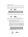
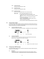
This section discusses how the transfer mechanism functions, and how to transfer data,
command list, event driven write commands, and configuration data to the ProSoft
module.
Data transfer to the module from the processor is executed through the Block Transfer
Write function. The different types of data which are transferred require slightly different
data block structures, but the basic data structure is:
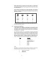
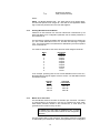
Word
0
1-63
Description
Block ID code
Data
In a PLC, the BTW length must be configured for 64 words, otherwise module
operation will be unpredictable.
Where:
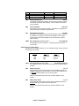
Block ID Code: A block identifier code between 0 and 255 in value. This code is used
by the ProSoft module to determine what to do with the data block. Valid codes are:
Code
0-79
80-99
255
Description
Module Data Memory
Command List
Module Communication Configuration
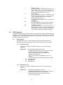
Data: The data to be written to the module. The structure of the data is dependent on
the Block ID code. The following sections provide details on the different structures.
3.1.1
Communications Configuration [Block ID Code 255]
The ProSoft Technology firmware communication parameters must be
configured at least once when the card is first powered up, and any time
thereafter when the parameters must be changed.
On power up, the module enters into a logical loop waiting to receive
configuration data from the processor. While waiting, the module sets the first
word of the BTR buffer to 255, telling the processor that the module must be
configured before anything else will be done. The module will continuously
perform block transfers until the communications configuration parameters
block is received. Upon receipt, the module will begin execution of the
command list if present, or begin looking for the command list from the
processor.
Transferring the Communications Configuration Parameters to the
module will force a reset of the communication port, as well as dropping
DTR three times (200 ms pulses) to reset any attached hardware.
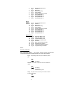
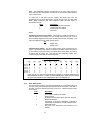
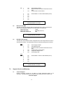
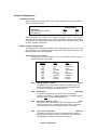
The configuration data block structure which must be transferred from the
processor to the module is as follows:
Data
Word
Description
Block ID Header = 255
Port 1
5