1
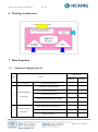
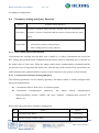
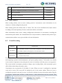
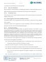
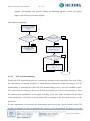
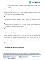
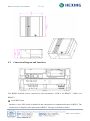
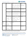
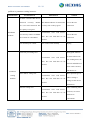
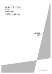
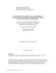
User Manual HXET100 Data Concentrator Hexing Electrical Co., Ltd. www.hxgroup.cn 2013.3 Data Concentrator User Manual 2 / 34 TABLE OF CONTENT INTRODUCTION .............................................................................................................................................................. 4 1 OVERVIEW .............................................................................................................................................................. 5 2 MAIN FEATURES ................................................................................................................................................... 6 3 APPLIED STANDARDS .......................................................................................................................................... 6 4 TECHNICAL SPECIFICATIONS .......................................................................................................................... 7 5 DATA TRANSMISSION CHANNELS ................................................................................................................... 7 6 WORKING ARCHITECTURE ............................................................................................................................... 8 7 MAIN FUNCTIONS ................................................................................................................................................. 8 8 7.1 FUNCTION CONFIGURATION LIST ......................................................................................................................... 8 7.2 DATA COLLECTION ............................................................................................................................................... 9 7.3 TYPE OF DATA COLLECTED ................................................................................................................................ 10 COLLECTION TYPE AND EXCEPTION MAINTENANCE........................................................................... 11 8.1 METER DATA COLLECTION ................................................................................................................................ 11 8.1.1 Collection Types-Time ................................................................................................................................. 11 8.1.2 Collection Types-Communication Medium ................................................................................................. 12 8.2 DATA RETRIEVE .................................................................................................................................................. 13 8.3 DATA STORAGE AND MANAGEMENT .................................................................................................................. 13 8.3.1 Storage Requirement ................................................................................................................................... 14 8.3.2 Meter Running Status Monitoring and Management .................................................................................. 14 8.4 PARAMETER SETTING AND QUERY FUNCTION ................................................................................................... 15 8.4.1 RTC Calling and Synchronization............................................................................................................... 15 8.4.2 Concentrator Parameter Setting and Query ............................................................................................... 15 8.4.3 Meter Achieves ............................................................................................................................................ 16 8.5 EVENT RECORDING ............................................................................................................................................. 16 8.6 LOCAL STATUS INDICATING................................................................................................................................ 19 8.6.1 Local Status Indicating ............................................................................................................................... 20 8.6.2 Local Maintenance Interface ...................................................................................................................... 20 8.6.3 Local Extension Interface ........................................................................................................................... 20 8.7 MAINTENANCE OF DATA CONCENTRATOR AND METER.................................................................................... 20 8.7.1 Self-testing and Abnormal Records ............................................................................................................. 20 8.7.2 Initialization ................................................................................................................................................ 21 8.7.3 Remote Upgrade of Concentrator and Meter Software .............................................................................. 22 8.8 REMOTE CONTROL .............................................................................................................................................. 24 8.9 COMMUNICATION OPTIMIZATION FUNCTION .................................................................................................... 25 8.9.1 Uplink Communication Optimization Strategy ........................................................................................... 25 8.9.2 Downlink Communication Optimization Strategy ....................................................................................... 25 8.10 EXCEPTION HANDLING ................................................................................................................................... 26 Data Concentrator User Manual 9 10 11 3 / 34 DIAGRAMS AND INSTALLATION INSTRUCTION ...................................................................................... 26 9.1 DIMENSION........................................................................................................................................................... 26 9.2 CONNECTION DIAGRAM AND INTERFACES ......................................................................................................... 27 9.3 LIGHT INDICATORS ............................................................................................................................................. 28 9.4 INSTALLATION ..................................................................................................................................................... 29 DEBUGGING AT SITE-FAQ ................................................................................................................................ 30 10.1 COMMUNICATE FAILURE BETWEEN CONCENTRATOR AND MASTER STATION............................................ 30 10.2 COMMUNICATE FAILURE BETWEEN CONCENTRATOR AND METER ............................................................. 31 TRANSPORTATION AND STORAGE ............................................................................................................... 33 Data Concentrator User Manual 4 / 34 Introduction Range of validity The present user manual applies to the meter specified on the title page. Purpose The user manual contains all the information required for application of the equipment for the intended purpose. This includes: Provision of knowledge concerning characteristics, construction and function of the data concentrator Information about possible dangers, their consequences and measures to prevent any danger Details concerning the performance of all work throughout the service life of the data concentrator Target group The contents of this user manual are intended for technically qualified personnel of energy supply companies responsible for the planning, installation, operation, and maintenance of the data concentrator. Hexing Electrical reserves the right of final interpretation Data Concentrator User Manual 5 / 34 1 Overview (for reference) Intelligent data concentrator is one important part of AMI system and remote prepaid system. HXET100 data concentrator is a low voltage centralized meter reading terminal, with a highperformance 32-bit ARM9 core hardware platform and embedded Linux operating system, which enables a huge space for function extension and system upgrade. It can collect and save various types of data of electricity meter by presetting or timing, and exchange data with system master station via wire wireless module (GPRS) or Ethernet. The HXET100 data concentrator has a large data storage space of 256M, and can ensure that data can be stored for 10 years without losing after power failure. It is equipped with various local communication ports, such as far-infrared, RS485, PS/2 .etc. During the R& D process of this product, the various suggestions and advice from the relevant R&D Institute, manufacturers, and end users have been taken into consideration. Besides, Hexing R& D team takes full advantage of the great experience accumulated over the years during the development process of electricity meters and terminal products, combined with the standards of the State Grid of China and of foreign countries, as well as the state-of-the-art mobile communications technology and high-precision energy metering technology. All of these ensures the powerful functions of this product, such as remote meter reading, energy metering, demand recording, power quality measurement, initiative reporting, low voltage PLC meter reading etc. In addition, it features in easy and stable operation, easy maintenance, high reliability, large storage capacity, open and costeffective. Data Concentrator User Manual 6 / 34 2 Main Features PLC adopts the B-PSK technology to fit with all kinds of environment and compatible with other manufacturer’s products. Integrated with Lontalks protocol to make sure the net is much more convenient and reliable; Advanced ARM9 hardware module, run by LINUX embedded operating system to ensure realtime and steady power net; Comply with IP51 standard and EN60950 standard, fit with all kinds of bad environment; Comply with several kinds of meter reading communication protocol, such as DLMS/COSEM.etc; Comply with several communication channels, such as GPRS, Ethernet. Due to running under LINUX system, it complies with standard internet protocol: PPP, TCP, UDP, FTP and so on; 256MB data storage capability with YAFFS2 document system which supports multiple file formats; Remotely updating application program and remotely downloading customized applications; Auto stat relay road. It can remember, choose, optimize, and quickly re-organize the net structure of the relay road. Enlarge the communication distance, improve the billing efficiency, the longer the system used, the more information will be stored in the net, the success ratio is up to 100% of system day time billing; 3 Applied Standards ISO: International Organization for Standardization IEC: International Electricity Committee IEEE: Institute of Electrical & Electronic Engineers IEC 60870-5-102 Telecontrol equipment and systems - Part 5: Transmission protocols - Section 102: Companion standard for the transmission of integrated totals in electric power systems IEC62056-46 Electricity metering -Data exchange for meter reading, tariff and load control Part 47: Data link layer using HDLC protocol IEC 61000-4 Testing and measurement techniques-Immunity to conducted disturbances, induced by radio-frequency fields EIA709.1 A Standard, Control Network Protocol Specification, ANSI/EIA, Arlington, USA; April 1999 EIA709.2 A Standard, Control Network Protocol Specification, ANSI/EIA, Arlington, USA; April 1999 IEEE 802.15.4 MAC 7 / 34 Data Concentrator User Manual 4 Technical Specifications Items Parameters Voltage range Rated Frequency Power consumption in voltage circuit Power supply type 80V-460V 50Hz-60Hz ≤5W switching power supply Operating system LINUX Memory capacity 32MB Storage capacity 256MB RTC accuracy Battery capacity(RTC) Protection degree 0.5s/day 1200mAh Lithium battery IP51 Operating temperature -40℃~80℃ Operating temperature limit -45℃~85℃ Storage and transportation temperature -30℃~70℃ Relative humidity Dimensions Weight ≤95% 175mm*172mm*76mm 1.22kg 5 Data Transmission Channels The data transmission channels of HXET100 data concentrator is as follows: Functions Description Up-Link Communication GPRS/Ethernet/RS485/PS2 External interfaces USB2.0 Down-Link Communication Zigbee/PLC/RS485 Data Concentrator User Manual 8 / 34 6 Working Architecture 7 Main Functions 7.1 Function Configuration List Configuration No. Items Mandatory 1 Data collection Collection of meter data √ Real-time and current data √ Historical daily data √ Historical monthly data √ Collection of important users’ data √ optional Data management 2 and storage √ Monitoring of meter running status RTC calling and synchronization √ Data concentrator parameters √ Meter parameters √ Parameter setting 3 and Query Data Concentrator User Manual 9 / 34 Configuration No. Items Mandatory optional Other(threshold value, prepaid √ information .etc) parameters 4 5 Important events record √ General events record √ Running status indication √ Local maintenance interface √ Event recording Local functions √ Local extension interface self-checking and self-restoration √ Data concentrator initialization √ Maintenance of data 6 concentrator and Remote download of data concentrator and √ electricity meters meter’s software Remote connection and disconnection of 7 √ Remote control meter’s relay data transmission Initiatively send, and send after calling by type master station √ 8 7.2 Data Collection Function Data collection Description The data concentrator achieves collection and storage of meter data 1. Task data, daily frozen energy data, daily frozen prepaid data, monthly frozen data data 2. Reading of specific data selected by user thru master station 3. Collection of real-time data and instantaneous values Data Concentrator User Manual 7.3 10 / 34 Type of Data Collected The data concentrator collects real-time energy data, daily frozen energy data, and monthly frozen energy data of meters. These data are saved with the exact meter-reading time. Below is the list of data collected by the data concentrator. No. Data Data source 1 Real-time voltage and current of 3-phase meter 2 Real-time 3-phase total active power and active power of each phase Meter 3 Real-time 3-phase total active power and reactive power of each phase meter 4 Real-time power factor meter 5 Current active(+) energy consumption data(total and each tariff) Meter 6 Current reactive(+) energy consumption data Meter 7 Current active(-) energy consumption data(total and each tariff) Meter 8 Current reactive(-) energy consumption data meter 9 Current quadrant I/IV reactive energy consumption data meter 10 Current quadrant II/III reactive energy consumption data Meter 11 Meter calendar and RTC Meter 12 Meter event status word Meter 13 Meter remote control status and record meter 14 Event meter 15 Daily frozen energy data Meter 16 Daily frozen prepaid information data Meter 17 Monthly frozen energy data Meter 11 / 34 Data Concentrator User Manual 8 Collection Type and Exception Maintenance 8.1 Meter Data Collection 8.1.1 Collection Types-Time Concentrator supports collection and storage of at least 1200 meters’ data. There are two types of task collection according to the collection time, namely, random collection and scheduled collection. 8.1.1.1 Random Collection Concentrator collects specified meters’ relevant data, configured parameters, and abnormal events directly according to the master station’s command by master station repeating meter reading method. With this method, the concentrator receives master station’s command and transmits it directly to the meter, waits for the meter to return the data and then transmits meter’s response data to the master station. During this period, the concentrator doesn’t make any processing to the command. Repeating reading data items No. Data Data source 1 Real-time voltage and current of 3-phase Meter 2 Real-time 3-phase total active power and active power of each phase Meter 3 Real-time 3-phase total active power and reactive power of each phase Meter 4 Real-time power factor meter 5 Current prepaid information meter 6 Current active(+) energy consumption data(total and each tariff) Meter 7 Current reactive(+) energy consumption data Meter 8 Current active(-) energy consumption data(total and each tariff) Meter 9 Current reactive(-) energy consumption data Meter 10 Current quadrant I/IV reactive energy consumption data Meter 11 Current quadrant II/III reactive energy consumption data Meter 12 Meter calendar and RTC Meter 13 Meter event status word Meter 12 / 34 Data Concentrator User Manual No. Data 14 Meter remote control status and record Meter 15 Event Meter 8.1.1.2 Data source Scheduled Collection Scheduled Collection is that: Concentrator automatically collects data collector or meters’ data according to the configured meter reading scheme, and automatically transmits the data to master station in the form of a task. The task can flexibly configure the data items required for the collection, and can set the collection time and transmission time interval in accordance with the task. Scheduled reading data items 8.1.2 No. Data Data source 1 Daily frozen energy data Meter 2 Daily frozen prepaid information data Meter 3 Monthly frozen energy data Meter Collection Types-Communication Medium Depending on the communication medium, it can be divided into local PLC communication module collection and RS485 collection. 8.1.2.1 Local PLC Communication Module Collection Local PLC communication module collection: it uses the low voltage distribution lines as a medium of information transmission, and transmits the digital signal by PLC. The communication module of concentrator adopts the SSC (spread spectrum communication) with high signal-to-noise ratio, and therefore features in strong anti-interference and high stability. Performance of local PLC communication interface No. Items Performance parameters 1 transmission speed ≥600 bps 2 transmission bit error rate ≤10-5 3 Transmission distance 200m~300m, can automatically repeat for 500m~1500m 13 / 34 Data Concentrator User Manual 4 success rate of one collection ≥85% 5 success rate of period ≥95%, period is 1 day Meter reading time of data 6 <5s, collect current active(+) energy consumption data concentrator 7 8.1.2.2 Time for data collection <1200 meters, 4~6 hours for collecting daily data RS 485 Collection RS485 collection: can directly connect to meter by RS485. This method features in stable communication, little environment affection, high success rate of meter reading, high transmission rate .etc. 8.2 Data Retrieve The concentrator can retrieve the collected data. If the data is wrong, it will set the data as null. If the data is not complete, they can be recalled. 3-day’s daily frozen data can be recalled. 8.3 Data Storage and Management Function Description data storage and management To realize data storage and management function 1. Data storage function 2. Abnormal events storage and handling Requirements 3. Monitoring and management of meter running status Concentrator classifies the collected data according to requirement. The classification can be daily frozen energy consumption data, daily frozen prepaid information data, historical data, etc. Abnormal events will be initiatively reported. Below table shows the stored data items: Data storage No. Data Data source 14 / 34 Data Concentrator User Manual No. Data Data source 1 Storage of daily frozen energy consumption data Meter 2 Storage of daily frozen prepaid information data Meter 3 Storage of monthly frozen energy consumption data Meter 4 Daily active(-) energy consumption data(total and each tariff) Meter 5 Daily reactive(-) energy consumption data Meter 6 Daily quadrant I/IV reactive energy consumption data Meter 7 Daily quadrant II/III reactive energy consumption data Meter 8 Active MD value and occurring time on billing date Meter 9 Active(+) energy consumption data(total and each tariff) on billing date Meter 10 Reactive(+) energy consumption data on billing date Meter Meter running status monitoring and management 8.3.1 No. Data Data source 1 Event status reading Meter 2 Event reading, storage, and initiative reporting to the master station Meter Storage Requirement 1) The data storage space of concentrator is not less than 256M; 2) The concentrator can classify and save below data: Freeze each meter’s daily energy data at 00: 00: 00, totally 2 months’ data; Daily freeze prepaid information data Freeze meter’s monthly energy data at 00:00, 1st day of each month, totally 12 months’ data 8.3.2 Meter abnormal events data Meter Running Status Monitoring and Management Concentrator can monitor the running status of meter. It can record meter’s various events such as standard event, fraud event, power grid event, relay event, and the relevant occurring time according to the requirements of the event, save meter’s abnormal data, and report to the master station 15 / 34 Data Concentrator User Manual according to configuration. 8.4 Parameter Setting and Query Function Function Parameter setting and Query To achieve parameter setting and query function, when the concentrator sets Description parameters, it must be completed within the timeout period issued by the master station. Requirement 8.4.1 1. RTC calling and synchronization 2. Concentrator parameter setting and query 3. Meter reading parameter setting and query RTC Calling and Synchronization Concentration has a timing unit, the daily error of which is ≤±1s/day. Concentrator can receive the RTC calling and synchronization command from the master station or hand held unit. It can also set the initial value of clock error. When the master station issues synchronization command and the current clock error is larger than the initial value, then this log will be recorded. The concentrator can make broadcast time synchronization for meters or data collectors in the system via local channel. 8.4.2 Concentrator Parameter Setting and Query The following parameters can be remotely queried by the master station or locally configured and queried by hand held unit. Concentrator archive, such as No. of collection points Concentrator communication parameters, like master station communication address(including primary channel and spare channel), communication protocol, IP address .etc. Below table shows the major parameter configuration. No. Items Objects 1 Concentrator logic address Concentrator 2 IP address and port of master station Concentrator Data Concentrator User Manual 8.4.3 16 / 34 3 Configuration of meter reading operation parameters Concentrator 4 Equipment configuration parameters of concentrator and meter Concentrator 5 Tasks configuration Concentrator 6 Event status configuration Concentrator 7 Uplink communication parameter configuration Concentrator Meter Achieves Meter reading scheme, such as meter reading period of concentrator, meter information can be remotely or locally configured and queried. Meter reading period: the default value is 8 hours. The value can be modified in the master station according to the actual quantity of meters connected with the concentrator. Meter information means meter reading configuration information of concentrator, including the measurement point number, the communication rate and port number, communication protocol type, communication address, user types and other relevant information. 8.5 Event Recording Function Event record The concentrator classifies event records as important events and general events Description in accordance with the event properties set in the master station. 1. Important events record 2. General events record Requirement Event log and alarm are the important functions of the concentrator. They play an important role for anti-tampering, operation fault maintenance, and power quality analysis. Concentrator can classify event records as important events and general events in accordance with the preset event properties. The events include concentrator parameters change, meter reading failure, and concentrator power off/on. Below table shows the major events. Concentrator can set properties of all kinds of events. When an event is configured to important event and it occurs, this event will be initiatively sent to the master station. When an event is configured to general event and it occurs, it will not be initiatively sent to the master station. But the concentrator’s uplink report will have a mark position 1, which means that event has occurred. Then 17 / 34 Data Concentrator User Manual the master station can recall the events later. The events can be classified concentrator events and the meter events according to the event occurring subject. Below table shows the classification of events. Concentrator events list No. Data Data source 1 Data initialization and version change record Concentrator 2 Parameter lost record Concentrator 3 Parameter change record Concentrator 4 Standard events Meter events 5 Fraud events Meter events 6 Relay events Meter events 7 Power grid events Meter events 8 Concentrator failed in meter reading Concentrator Meter events list No. Data Data source Meter standard events 1 DST switching, record the time before switching Standard events 2 RTC change-the time before change Standard events 3 RTC change-the time after change Standard events 4 RTC error Standard events 5 Battery needs replacing Standard events 6 Clear error register Standard events 7 Clear alarm register Standard events 8 Program memory error Standard events 9 Data memory error Standard events 10 Memory hardware error Standard events 11 Abnormal reset Standard events Data Concentrator User Manual 18 / 34 12 Metering system error Standard events 13 Software upgrade preparation Standard events 14 Software upgrade failed 15 Software upgrade finished Standard events 16 Switch from postpay mode to prepaid mode Standard events 17 Switch from prepaid mode to postpay mode Standard events 18 Clear all above events Standard events Tampering events 1 Open meter terminal cover Fraud events 2 Close meter terminal cover Fraud events 3 Strong magnetic field starts Fraud events 4 Strong magnetic field ends Fraud events 5 Open meter cover Fraud events 6 Close meter cover Fraud events 7 many times of communication key mistake Fraud events 8 Open module cover Fraud events 9 Close module cover Fraud events Relay events Remote relay disconnection-primary relay(enters remote 1 Relay events control mode) Remote relay reconnection-primary relay(exits from 2 Relay events remote control mode) 3 relay disconnection due to out of credit(prepaid meters) Relay events 4 relay reconnection after recharging(prepaid meters) Relay events Relay disconnection due to load control(Over the load 5 Relay events threshold) 6 Load returns to normal value, reconnect the relay Relay events 7 Energy-saving operation Relay events 19 / 34 Data Concentrator User Manual 8 Cancel energy-saving Relay events 9 primary relay disconnect(physically) Relay events 10 primary relay reconnect(physically) Relay events Power grid events 1 Meter power off Power grid events 2 Meter power on Power grid events 3 Meter under voltage Power grid events 4 Meter restore voltage Power grid events 5 Meter current loss Power grid events 6 Meter restore current Power grid events 7 Meter over voltage Power grid events 8 Meter restore voltage Power grid events 9 Reverse phase sequence start(phase 0) Power grid events 10 Reverse phase sequence end(phase 0) Power grid events 11 Current reverse ends Power grid events 12 Current reverse starts Power grid events 3-phase unbalance starts(the power exceeds the meter’s 13 Power grid events preset threshold limit) 14 8.6 3-phase unbalance ends Power grid events Local Status Indicating Function Local Status Indicating function It has functions like concentrator local status indication, local parameter Description settings, software upgrades, local maintenance and extension interface. Requirement 1. Display or indicate relevant information 2. Local maintenance interface 3. Local extension interface Data Concentrator User Manual 8.6.1 20 / 34 Local Status Indicating It has working status, communication status indicating functions. Please refer to the instructions for indicator lights for details. 8.6.2 Local Maintenance Interface It provides with local maintenance interface, supports setting parameters via handheld devices and reading energy data at site, and adopts security measures like permissions and password management such as to prevent unauthorized personnel operation. 8.6.3 Local Extension Interface It has local USB2.0 interface function, which enables upgrade or data export via local interface. 8.7 Maintenance of Data Concentrator and Meter Function Terminal maintenance Realize concentrator self-testing, self-diagnosis, initialization, remote Description upgrade, etc. Requirement 8.7.1 1 Self-testing and self-restoration function 2 Concentrator initialization function 3 Concentrator and meter software remote downloading Self-testing and Abnormal Records Concentrator can make self-checking automatically. When it detects equipment abnormal(including communication), it will record events and alarms. Concentrator has the hardware clock chip that enables clock synchronization per second. 8.7.1.1 Meter Self-diagnosis and Abnormal Alarm Definition: meter can make corresponding changes thru internal status word. Judgment method: by detecting meter status word, concentrator can judge and determine whether event occurred or not. Judgment recovery time: 1 hour by default. 8.7.1.2 Communication Self-testing Function After terminal power on, it makes communication with communication module every 30s to query Data Concentrator User Manual 21 / 34 parameters of communication module, such as APN, message center, communication addresses of master station, working condition of communication module .etc. If it discovers that the collected information is different with the information stored in the terminal, the terminal will make the relevant setting on it. Below contents need to be clarified. Currently, the communication module does not store any information, that is to say, as long as the communication module is powered on/reset, all information will be restored to its original state. Therefore, when the terminal is powered on, there will be one parameter setting to the communication module. After that, communication module can run normally. Since the channel information stored in the terminal may contain local channel (such as PS2 interface, USB interface), for which there is no need to set inside the communication module. Therefore, once the terminal discovers that the channel of information is for the local channel, it will set the corresponding channel information in the communication module as invalid. When the terminal sends heartbeat several times or other uplink report receives no response, the terminal will automatically make offline reconnection. The concentrator can set heartbeat cycle with different time intervals (such as 5 minutes, 15 minutes) according to network condition so as to ensure the normal connection of network communication. If concentrator can’t login to the master station for a long time, it will record login failure log file. 8.7.2 Initialization After concentrator receives the initialization and hardware reset commands from the master station or PC software, it can make initialization to parameters area and data area respectively. The parameters area will be set to the default and data area will be reset to zero. Hardware reset does not involve emptying the parameters and data. 8.7.2.1 Hardware Initialization The hardware reset function of concentrator does not remove any parameters and stored data, which Data Concentrator User Manual 22 / 34 is equivalent to a concentrator power off/on operation. 8.7.2.2 Data Area Initialization Keep concentrator’s internal parameters, including logical addresses, measurement point parameters, uplink communication parameters, task allocation, and clearing of meter reading data. 8.7.2.3 Concentrator Clear After concentrator clear, all data inside the concentrator will be cleared. Parameters are initialized to default ex-factory value. 8.7.3 Remote Upgrade of Concentrator and Meter Software Concentrator software can be upgraded both locally and remotely. Concentrator can also upgrade meter’s program. Concentrator software can be upgraded by message downloading or FTP auto downloading. Both approaches can realize remote file downloading and upgrade. 8.7.3.1 Message Downloading When using the message downloading method, the application function of “file transfer” in the communication protocol of concentrator is used. First split the file into N equal sections, and then through message exchange methods, these small files with fixed number are sent to the concentrator in turn with segmentation stream. After concentrator receives all the message sections, it joins them together into a complete file. In the process of transmission, response validation mechanism, identity authentication and other verification process will be used to ensure correctness and completeness of the file transfer. Concentrator supports continuing transferring from breakpoint. To try to speed up the remote upgrade process and improve its flexibility, the following mechanisms are used for the remote upgrade of concentrator. The data transmission during upgrade process is unidirectional, which cancels the process for the master station to wait for the concentrator’s response. Before and after the upgrade, concentrator parameters will not be lost. If the data is incomplete in the upgrade, the data will be rejected and not upgraded. When the concentrator and meter receive the upgrading data, verification will start and if the data is correct, the data will be upgraded. The upgrade of program is very fast. Normally less than one s. Concentrator upgrade process is continued in data blocks, this combines both the main 23 / 34 Data Concentrator User Manual program downloading and protocol library downloading together, which can greatly improve the efficiency of remote upgrade. Flow chart for upgrading: Receive the downlink message from master station Y Transmit file? N Processing and responding of other commands N Method 1 (protocol transmission) Y Transmit from the 1st segment of the file Y File transmission finish? N Transmit next segment of file 8.7.3.2 FTP Auto Downloading During the FTP downloading process, concentrator belongs to the connecting client side. When the concentrator is running normally, it automatically monitors the related parameters of FTP downloading. It automatically starts the FTP downloading process, and will establish remote TCP connection according to the server IP and port number provided in the parameters. Once the connection is established, it will login according to the user name and password provided in the parameters. After that, it can download file according to the specified directory in the parameter. For the convenience of operation, the downloading process uses the "passive mode" in the FTP method. In addition, in order to guarantee the security of file downloaded, it is better to use the Data Concentrator User Manual 24 / 34 non-anonymous way to log in to download. In the process of the FTP downloading, connection interruption may happen. In order to avoid transmission from the beginning after interruption the downloading process needs to be monitored and saved. Therefore, it is possible to continue the transmission after recovery of connection. Compared to message downloading, this method is easier and faster, and does not need to control the file transmission process. However, it requires that the corresponding FTP server program started at the remote server before starting the transmission. And the downloaded files must be stored in the correct position and the corresponding user name and password is set. 8.7.3.3 Concentrator Upgrades Meter Software Concentrator upgrades program through the PLC communication. The master station sends program software to the concentrator; the concentrator will store program software and upgrade the program of meters under it. If error occurs or upgrade failed to some meters, the concentrator records the event and submits to the master station. 8.8 Remote Control Through the concentrator, the master station can make relay disconnection and reconnection operations to the meter. The concentrator gets relevant meter information then makes those operations accordingly. And it will reply to the maser station the information of meters that have been successfully disconnected or reconnected. "Electric power system load control" refers to achieving a planned, economical, and secure manner of electricity using via the control of load so as to reach orderly power utilization. Master station can control the meter in a variety of control modes via concentrator: Emergency control Power control Energy consumption control Data Concentrator User Manual 25 / 34 8.9 Communication Optimization Function 8.9.1 Uplink Communication Optimization Strategy In places where signal intensity is not high, the method of using a long antenna and increasing transmitting power of communication module will be used to solve the problem of poor communication due to low signal intensity. Concentrator’s uplink task data are sent in package, which improves the efficiency of the uplink communication and reduces communication traffic(data flow amount). eg. task data of 8 meters can be packed and sent in one frame message. If the task data is sent meter by meter, it means the system tasks will be sent according to the number of meters, which will take up too much communication resources and increase the communication load. If the condition is extremely serious, the communication link will be blocked and made paralyzed. If the concentrator fails in sending uplink tasks and alarms due to network failure, it can store these data by itself so as to avoid data lost. Then master station can recall these data later thru the task and alarm recall system. The task data and all kinds of alarms data of concentrator adopt initiate reporting method. Therefore, the master station doesn’t need to call them. In this way, pressure of master station system is reduced, and the master station’s downlink traffic data is also reduced, which helps reduce the communication costs. Concentrator makes timely response to uplink command. The moment when it receives uplink command, it will start timing, and concentrator will reply the master station’s command within the specified response period. 8.9.2 Downlink Communication Optimization Strategy Frame head error: delete the first character, continue checking the frame format; Error in frame length, check code, and end code etc.: clear the receiving buffer Frame length is insufficient, that is, calculated frame length according to the frame format > actually received frame length: keep waiting. Concentrator has two meter reading command queues: Queue 1: for repeating, with the highest priority Data Concentrator User Manual 26 / 34 Queen 2: for meter reading at regular time and scheduled meter reading, with the lowest priority When concentrator needs to read the meter, the command will be filled into the above two queues as per the priority of command. When concentrator finds port is free, it will take command from the queue according to the queue priority, and save to sending buffer for sending. Concentrator can optimize and pack the downlink data. When concentrator receives many commands to one same meter from the master station, it will pack the data items according to the transmitting length limit and send the package to the meter. The length limit varies for different communication methods, such as PLC and RS485. Concentrator can make broadcast to different meters for the same command. When all the meters receive the command, they will do the same operation, such as broadcast time synchronization, and broadcast relay disconnection. The timeout period is set when the concentrator is reading the meter. If it does not receive the data within the prescribed period, it will make relevant timeout processing. 8.10 Exception Handling When the concentrator is configured locally or remotely, and the password does not match or the user’s permission does not match, concentrator will respond “setting operation refused” and will record the time document. When wrong data is used to operate the concentrator, it will respond failure information. The user can input password many times if it is wrong. The default input times is three. 9 Diagrams and Installation Instruction 9.1 Dimension The outline dimension of the concentrator is 175mm*171mm*76mm, as shown in below diagram. Data Concentrator User Manual 9.2 27 / 34 Connection Diagram and Interfaces Two RS485 terminals can be connected to the concentrator. 1A1B is for RS485-1, 2A2B is for RS485-2. Local RS232 port Interface: 6-core PS/2 socket is installed in the concentrator as communication port for RS232. The electrical level complies with requirement of RS232. The pins are defined as below: Data Concentrator User Manual PS/2 socket 28 / 34 pin signal 1, 2 earth 3, 5 Txd 4, 6 Rxd definition of RS-232 pin Communication baud rate: 2400bps. Even parity check, one stop bit. 9.3 Light Indicators Light indicators Description Power indicator, red. When the concentrator is powered on, the light is on Power all the time. Running indicator, red. When the concentrator is powered on, the light Run will blink. It means the concentrator is working normally. Phase A indicator, green. When it is on all the time, it means phase A is Ua powered on. Phase B indicator, green. When it is on all the time, it means phase B is Ub powered on. Phase C indicator, green. When it is on all the time, it means phase C is Uc powered on. Alarm Event alarm indicator, red. When it is on all the time, it means the Data Concentrator User Manual 29 / 34 concentrator has events to be reported to the master station. Ethernet indicator, green. When it is on all the time, it means the WAN concentrator is communicating with master station via Ethernet currently. RS485 data receiving and transmitting indicator, red and green. When the red light is always on, it means the concentrator receives data from 485-1. 485-1 When the green light is always on, it means the concentrator sends data to 485-1. RS485 data receiving and transmitting indicator, red and green. When the red light is always on, it means the concentrator receives data from 485-2. 485-2 When the green light is always on, it means the concentrator sends data to 485-2. PLC data receiving and transmitting indicator, red and green. When the red light is always on, it means the concentrator receives data from PLC. PLC When the green light is always on, it means the concentrator sends data to PLC. GPRS module power indicator, green. When it is always on, it means GPRS GPRS module is powered on. GPRS data receiving and transmitting indicator, red and green. When the green light is blinking, it means GPRS is searching for mobile network. Rx/Tx When green light and red light is alternately blinking, it means GPRS is online. 9.4 Installation For the installation as site, please connect system voltage Ua,Ub,Uc,Un respectively, and put the SIM card. When the concentrator is connected to the power supply, the power indicator is on. If the Data Concentrator User Manual 30 / 34 communication parameters are right, concentrator can log in to the master station. When the running indicator is blinking, it means concentrator and master station has been successfully connected. The installation process is finished. 10 Debugging At Site-FAQ 10.1 Communicate Failure between Concentrator and Master Station This refers to master station cannot receive the data from concentrator, or master station cannot communicate with concentrator. The reasons can be: installation problem, ISP fault, parameter setting error, master station channel problem. Classification Installation Possible Reason SIM Card poor contact Fault Phenomenon Solution Concentrator cannot log on. Its network Power off at light blinks alternately. Master station reinstall SIM Card. site, cannot communicate with concentrator. Antenna loose Concentrator cannot log on. Its network Reinstall antenna light blinks alternately. Master station cannot communicate with concentrator. Not powered on Concentrator running light is not on. Make sure the power supply wiring is correct, and circuit is powered on. ISP Fault No network coverage in the Concentrator cannot log on. Its network local light blinks alternately. Master station cannot communicate with concentrator. Contact ISP 31 / 34 Data Concentrator User Manual Poor signal in the local Concentrator indicates that signal Replace external strength is low, or signal strength antenna, move external indication is unstable, sometimes high, antenna’s position. and sometimes low. Master Station communication is always intermitted. SIM Card damaged or error Concentrator cannot log on. Its network Change SIM Card light blinks alternately. Master station cannot communicate with concentrator. SIM card doesn’t open Network indication and signal strength Inform ISP to open the relevant service or has been are normal. But master station cannot relevant closed due to running out of communicate with concentrator. charge the card. When public network is Concentrator’s Resetting using GPRS frequently, which leads to master station shake communication service and credit. for Communication, hand interval is not IP is failure changing with concentrator. But the concentrator can correctly set. upload data successfully. Parameter GPRS Concentrator cannot log on GPRS Setting Parameter Setting Problem Incorrect(APN, Master Communication Resetting Network Station IP etc) Other Reasons When the master station creates concentrator’s Modify archive archive, logical address is input wrong. 10.2 Communicate Failure between Concentrator and Meter This refers to that concentrator cannot read meter data successfully. The reasons can be installation 32 / 34 Data Concentrator User Manual problem or parameter setting incorrect. Classification Possible Reason Phenomenon Solution Terminal A and B of RS 485 are connected reversely. RS485 wire is not well connected. The The RS485 indicator of concentrator Correct the wire is always red or always green. connection. wire quality is not good. Installation problem Concentrator can’t read meter’s Not correctly connect to RS485 Correct the wire data. The sent load data are all port of meter or concentrator. connection. invalid. PLC modules poor contact PLC cannot work normally Protocol or port setting error Replug Through the function of master station realConcentrator can’t read meter’s time reading meter, the data. The sent load data are all protocol and address of invalid. meter can be ensured, and then be set. Parameter Meter address setting error Meter protocol type or Setting Concentrator can’t read meter’s Problem data. The sent load data are all address setting is wrong. Set the correct invalid. information. Baud rate setting error After confirming meter Concentrator can’t read meter’s baud rate, set correct data. The sent load data are all baud rate to invalid. concentrator. Data Concentrator User Manual Meter RS485 port is faulty 33 / 34 Concentrator can’t read meter’s Replace meter data. The sent load data are all invalid. Other reasons Meter unstable After concentrator communicates Replace meter with meter normally for a period, it suddenly can’t communicate with the meter. 11 Transportation and Storage During the transportation and packing process, the products shall not be dramatically shocked. And shall be transported and stored according to the regulations. Inventory and storage should be made in a shelf with original package. The piling height should be not more than eight layers. The storage place shall be clean, in which the ambient temperature shall be - 20℃ ~ 80 ℃ and relative humidity not more than 85%. And there are no harmful substances in the air that might cause corrosion. NOTE: Information in this document is subject to change without notice. The information is accurate at the time of printing (March, 2013) © Hexing Electrical Data Concentrator User Manual 34 / 34 Hexing Electrical Add: Shangcheng Industrial Zone, 1418 Moganshan Rd, Hangzhou, China TEL: +86-571-28020767/769 FAX: +86-571-28029263 www.hxgroup.cn [email protected]