1
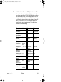
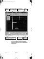
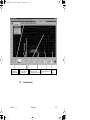
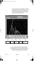
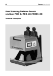
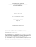
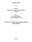
RS4so_DE.book Seite 88 Montag, 6. August 2001 2:42 02
When start interlock is active, the safety outputs of the
RS4-4 (OSSD 1 and OSSD 2) will not be enabled or switched
„active high“, even if the current detection zone is clear, until
the RESTART button has been actuated for a period of 2 to
4 seconds (24 V to pin 2 of interface X1).
When startup test is active, after the scanner has been
switched on, the safety outputs of the RS4-4 (OSSD1 and
OSSD2) will not be enabled or switched „active high“, even
if the current detection zone is clear, until the detection zone
is temporarily violated one time.
When restart interlock is active, the safety outputs
(OSSD 1 and OSSD 2) of the RS4-4 will not be enabled or
switched „active high“, even if the current detection zone is
clear, until the RESTART button has been actuated for a
period of 2 to 4 seconds (24 V to pin 2 of interface X1). This
function is active after every violation of the detection zone.
The dust suppression function of the ROTOSCAN RS4-4
is a software function for increasing the availability of the laser
scanner in the presence of dirt or small particles in the air,
such as insects. If dust suppression is activated, a somewhat
larger addition to the detection zone contour must be made.
With or without dust suppression, and with a detection zone
radius of up to 3.5 m, the addition has a value of 81 mm. With
activated dust suppression and a detection zone radius of
3.5 m or more, the addition has a value of 98 mm. The addition is shown in the echo data.
Please refer to Chapter 7 for information on defining detection
zones when the dust algorithm is active.
Due to its four freely programmable field pairs, the
ROTOSCAN RS4-4 can be used very flexibly in a wide range
of applications. The selected detection zones are checked for
plausibility when the admissible changeover sequence is
chosen in the dialog „Admissible field pair changeovers“.
Inadmissible changeover sequences are detected and cause
the OSSDs to be switched off. Furthermore, each field pair
can be defined as the system startup field pair.
These features are useful with automatic guided vehicles, for
instance, when the detection zone is changed over to accommodate straight and curved routes and when the vehicle
starts up in a straight section.
88
RS4soft
Leuze lumiflex
RS4so_DE.book Seite 89 Montag, 6. August 2001 2:42 02
Function button
"Change configuration
data"
Path within RS4soft
(from left to right)
Matrix for determining
admissible field pair
changeovers
Matrix for determining
admissible startup
field pairs
After the scanner configuration has been entered, it must be
transferred to the RS4; to do so, click on the function button
„Transfer configuration data from PC to RS4“. If you forget to
do this, the transfer dialog is automatically called up before
another subject button can be selected. Due to the safe protocol, you can now view and confirm the echo data reflected
by the scanner.
CAUTION! Since the PC is not a safety product and computer-specific errors can occur, the echo data transmitted by
the RS4-4 must be checked for errors and confirmed by an
authorized person.
Leuze lumiflex
RS4soft
89
RS4so_DE.book Seite 90 Montag, 6. August 2001 2:42 02
Display of RS4
echo data
Configuration
parameters
Selected
setting
Confirmation
button
If the echo data are returned accurately, you must confirm the
record by pressing the button „Accept“. Changing a configuration can require that the detection zones be checked again.
For information on the echo data, please refer to Chapter
7.13.
6.5.4 „Field pair 1 to 4" folders
Double-click on the folders to select the subfolders „detection
zone“ and „warning field“. Selecting one of these subfolders
causes field-specific data to appear in the right-hand section
of the dialog box: name of the field, date and time of the latest
change, field status, and information on admissible field pair
changeovers. In addition, the minimum object width is stated
with respect to the number of segments (x * 0.36˚). This
means that the lateral value in millimeters is dependent upon
the maximum radius of the field contour.
90
RS4soft
Leuze lumiflex
RS4so_DE.book Seite 91 Montag, 6. August 2001 2:42 02
6.6
Set standard values for RS4, Function Button
This function allows you to reinstate the factory-set configuration (delivery state) of the ROTOSCAN RS4-4. As an alternative to this function button, you can also press the RESTART
button (press pins 2 and 3 on connector X1) before switching
on the scanner. Release the button after approx. 2 seconds;
LEDs 2, 3 and 5 will be lit up in the scanner display. This
means that the scanner has been reset. The table below
describes the resultant setting:
Leuze lumiflex
Parameter
Value
Parameter
Value
Detection
zone range
4m
Application
Safeguarding an area
Detection
zone display
190°
Restart
Manual
Detection
zone response time
80 ms
Restart when
reset
Activated
restart
interlock
Field pair
changeover
No
changeover
Startup type
None
Startup field
pairs
1, 2, 3, 4
Dust algorithm
Activated
Detection
zone name
---
Start segment output
0
Warning field
range
5m
Stop segment
output
528
Warning field
display
190°
Baud rate
57600 bd
Warning
field, response time
80 ms
Name of the
scanner
---
Alarm signaling type
Violation of
the warning field
Description of
the scanner
---
RS4soft
91
RS4so_DE.book Seite 92 Montag, 6. August 2001 2:42 02
Please note that the reset function described above may not
be repeated for a period of 2 minutes.
After determining the scanner configuration, the setting must
be documented in suitable form at the monitored machine or
system. You need to generate a text file of the configuration
for this purpose.
The button „Generate text file“ allows you to do this. Clicking
on this button initiates a dialog for entering the file name and
converts the data into .txt format. To make a printout, open
the file (e.g. „RS4-4.txt“) in a word processing program such
as MS-Word® and click on the Print button.
The following information appears on the printout:
•
Date, user, data source
•
Scanner serial number, device type, software version
•
Non-safety-critical parameters
•
Safety-critical parameters
•
Information on the detection zones and warning fields of
all four field pairs
Read Chapter 9.1 to find out how to print out a detection zone
contour.
92
RS4soft
Leuze lumiflex
RS4so_DE.book Seite 93 Montag, 6. August 2001 2:42 02
7.
Define detection zones/warning fields,
Subject Button
This menu provides you with extensive possibilities for defining detection zones.
These include transferring data as well as creating and
modifying the detection zones (for detecting the presence
of personnel) and warning fields. Since this area involves
safety-relevant functions of the scanner, access is possible
only when the appropriate password is entered.
The smallest section of a detection zone must cover a lateral
distance of at least 3.5 cm. When defining detection zones,
make sure that no pin-shaped contours are set, as these do
not provide a guaranteed safety effect.
The maximum selectable detection zone radii vary depending
on the type of contour:
ROTOSCAN RS4-4
Range
Factory Setting
Detection zone
4m
4m
Warning field
15 m
5m
Contour measurement
50 m
---
The scanner is factory-programmed with semicircular detection zones (190˚) which will be in effect after the initial startup.
Please note that only detection zones (SF), and not warning
fields (WF), may be used for the performance of safetyrelated tasks.
Leuze lumiflex
RS4soft
93
RS4so_DE.book Seite 94 Montag, 6. August 2001 2:42 02
Load or save detection
zone/warning field data
Field catalog
Choose the basic
contours of the detection
zone/warning field
Base point of the X and Y coordinates
with the left and right field pair half
7.1
Tools for modifying the
basic contours
Factory-set detection
zones and warning fields
Data transfer
to the scanner
Optimizing
the display
Load detection zone/warning field from file,
Function Button
Click on this button to open a dialog box that will give you an
overview of the field configurations already saved on the PC
after you have entered the appropriate path and the file name.
You can call up the desired configuration (file extension „.sf“)
using the button „Open“ to make and confirm your selection.
See Chapter 7.13 for information on transferring the data.
94
RS4soft
Leuze lumiflex
RS4so_DE.book Seite 95 Montag, 6. August 2001 2:42 02
7.2
Save detection zone/warning field as a file,
Function Button
Click on this button to open a dialog box that allows you to
save the previously defined field configuration. Enter the path
and the file name. Click on the button „Save“ to confirm your
entry, and the configuration will be saved as an .sf file.
7.3
Select detection zone/warning field, Function
Button
When you click on this drop-down menu, all eight fields
(4 detection zones and 4 warning fields) will be displayed for
you to select. Use the mouse to click on the field pair you want
to define. The current contours of the detection zone and
warning field will be shown in red and green, respectively.
Unselected field pairs appear in gray/light gray.
7.4
Enter detection zone/warning field, Function
Button
Click on this button to open a dialog box for numerically
entering the dimensions of the detection zone/warning field
in millimeters. You can enter dimensions for the front, left and
right edges of the zone/field to be defined. Confirm the edge
dimensions. These will then be displayed on the screen in the
appropriate color (detection zone in red, warning field in
green).
Please refer to the subpoint „190˚ field pairs“ in Chapter 9.2 .
Leuze lumiflex
RS4soft
95
RS4so_DE.book Seite 96 Montag, 6. August 2001 2:42 02
7.5
Define elliptical detection zone/warning field,
Function Button
When you click on this button, all of the tools except Zooming
appear against a light gray background.
The program now waits for you to position the mouse pointer
and set the coordinates for the elliptical contour. You can
freely change the elliptical contour in the X- and Y-directions
as long as you keep the right mouse button pressed within
the contour field. The coordinate display is useful in helping
you check the dimensions as you set them. When you have
finished demarcating the field, release the right mouse
button. The set mouse pointer marks the intersection of the
horizontal and vertical line going to each side of the ellipsis.
Equivalent sections of the field are always generated in the
left and right halves of the display; these sections can be
modified separately at a later point in time.
Please refer to the subpoint „190˚ field pairs“ (see Chapter
9.2).
7.6
Define rectangular detection zone/warning
field, Function Button
When you click on this button, all of the tools except Zooming
appear against a light gray background.
The program now waits for you to position the mouse pointer
and set the coordinates for the rectangular contour. You
can freely change the rectangular contour in the X- and Ydirections as long as you keep the right mouse button
pressed within the contour field. The coordinate display is
useful in helping you check the dimensions as you set them.
When you have finished demarcating the field, release the
right mouse button. The set mouse pointer marks the corner
point of the horizontal and vertical line of the rectangle contour. Equivalent sections of the field are always generated in
the left and right halves of the display; these sections can be
modified separately at a later point in time.
Please refer to the subpoint „190˚ field pairs“ (see Chapter
9.2).
96
RS4soft
Leuze lumiflex
RS4so_DE.book Seite 97 Montag, 6. August 2001 2:42 02
Detection zones
and warning
fields, 1 to 4 each
X-line/Y-line intersection - defined
using the button "Define elliptical
detection zone/warning field"
Distinguishing between the left and right field
pair halves using a plus or minus sign
Defined using the button
"Define rectangular detection
zone/warning field"
Field pair center line
Selection of
five basic field
contours
Coordinates of
the mouse pointer
A minus sign preceding the mouse pointer coordinates
designates the left half of the field pair, or the area below the
scanner zero axis.
Leuze lumiflex
RS4soft
97
RS4so_DE.book Seite 98 Montag, 6. August 2001 2:42 02
7.7
Define polygonal detection zone/warning
field, Function Button
When you click on this button, all of the tools except Zooming
appear against a light gray background.
The program now waits for you to position the mouse pointer.
Click on the right-hand mouse button to „draw“ the contour of
the polygon point for point. The points along the contour are
always entered clockwise from left to right. As long as the
mouse button remains pressed within the contour field, you
can freely shift the current line segment in the X- and Y-directions. The coordinate display is useful in helping you check
the dimensions as you set them. Once you release the mouse
button, the process is complete and the line is set. Beginning
with the first point set by the mouse pointer, one line segment
is added to the contour with every click of the mouse button.
When the contour is complete, simply press the right-hand
mouse button.
Please refer to the subpoint „190˚ detection zones“ (Chapter
9.2).
98
RS4soft
Leuze lumiflex
RS4so_DE.book Seite 99 Montag, 6. August 2001 2:42 02
Button for
e.g. 1st, 2nd, 3rd and
activating the
4th mouse click for
polygon function the current field
7.8
Leuze lumiflex
End point set by
Displayed deactivated
clicking the right mouse
detection zone and
warning field (gray scale) button
Measured
contour
(freistehend)
RS4soft
99
RS4so_DE.book Seite 100 Montag, 6. August 2001 2:42 02
7.9
Change detection zone/warning field
segment, Function Button
Once a contour is specified, it can be modified by setting two
coordinate points with respect to the beam axis. When you
click on this button, all of the tools except Zooming appear
against a light gray background. The program now waits for
you to position the mouse pointer and click, thereby setting
the coordinates for the two coordinate points. Use the coordinate display to check your selection. The section of the contour between the points is a line showing the connections to
the previous contour. The connection itself follows the beam
axis. After you have set the first corrective point, the program
provides you with a yellow auxiliary line as a reference.
100
RS4soft
Leuze lumiflex
RS4so_DE.book Seite 101 Montag, 6. August 2001 2:42 02
Button for activating the segment
change (example: function active)
Connective lines following
the beam axis
Sample contour
for comparison
Auxiliary line
(beam axis)
First and second
coordinate point
7.10 Limit detection zones/warning field, Function
Button
Click on this button to open a dialog box that allows you to
limit the dimensions of the field by making a numerical input
in millimeters. This refers to the front, left and right edges of
the field. After you confirm the edge dimensions, the limited
contour will be displayed.
Leuze lumiflex
RS4soft
101
RS4so_DE.book Seite 102 Montag, 6. August 2001 2:42 02
Limiting measures to be
specified in the dialog
Button for activating
the segment limitation
Limited
contour
Sample contour
for comparison
7.11 Blanking out a detection zone/warning field
segment, Function Button
Once a contour is specified, you can blank out segments of
the detection zone by setting two coordinate points. The
segments between these two points will be blanked out.
When you click on this button, all of the tools except Zooming
appear against a light gray background.
The program now waits for you to position the mouse pointer
and click, thereby setting the coordinates for the beginning
and the end of the segment to be blanked out. The section of
102
RS4soft
Leuze lumiflex
RS4so_DE.book Seite 103 Montag, 6. August 2001 2:42 02
the contour between the points is blanked out in the direction
of the beam axis. After you have set the first corrective point,
the program provides you with a yellow auxiliary line as a
reference. The coordinate display is useful in helping you
check your setting of the blanked out area.
Button for activating
the segment change
Sample contour
for comparison
First and second
coordinate point
Auxiliary line
(beam axis)
Connective line following
the beam axis
If you blank out sectors that can be entered or walked
through, hazards to personnel can result if the minimum
safety distance is no longer met. Additional measures must
be taken to safeguard the danger zone in such cases.
Leuze lumiflex
RS4soft
103
RS4so_DE.book Seite 104 Montag, 6. August 2001 2:42 02
7.12 Delete detection zone/warning field, Function
Button
If you select this function, the detection zone definitions and
warning field definitions are replaced by the factory settings
(4 m radius for the detection zone, 5 m radius for the warning
field).
7.13 Transfer detection zone/warning field from
PC to RS4, Function Button
Click on this button to open a dialog box that gives an overview of the previously changed zone/field contours. This list
allows you to select the zones/fields that you want to be transferred to the RS4-4.
Once the dialog has been confirmed, the loading/saving
process begins and a progress bar appears on the screen.
The ROTOSCAN RS4-4 sends the information it received
back to the PC as echo data so that the data transfer can be
verified. The transferred detection zone contours appear in a
dialog; the contours must be checked and the dialog must be
acknowledged accordingly. After the check sums have been
recalculated, the transfer is concluded with an OK message.
CAUTION! Since the PC is not a safety product and computer-specific errors can occur, the echo data transmitted by
the RS4-4 must be checked for errors and confirmed by an
authorized person.
104
RS4soft
Leuze lumiflex
RS4so_DE.book Seite 105 Montag, 6. August 2001 2:42 02
Number of the
detection zone
Echo
dialog
Echo data contour
Registered maximum
values of the detection
zone
Automatically determined
detection zone addition
Date when admissible FP
changeovers were saved
Detection zone
to be transferred
The echo data contain the detection zone contours, the
maximum dimensions, the detection zone number, the date
and time they were saved, the admissible detection zone
changeovers, and the display of the detection zone addition.
The latter point must first be considered by the user when
defining the detection zones. For instructions on how to do
this, refer to the Technical Description of the ROTOSCAN
RS4-4.
Leuze lumiflex
RS4soft
105
RS4so_DE.book Seite 106 Montag, 6. August 2001 2:42 02
After the detection zone definition has been completed, the
configuration must be documented in a suitable form at the
monitored machine or system. Please see Chapter 9.1.
8
RS4 system data, Subject Button
This menu allows you to call up device-specific identification
data and special functions.
8.1
Load system data from the RS4, Function
Button
Click on this function button to transfer device data with a
logistical emphasis from the RS4-4 to the PC:
•
Software version (Firmware)
•
Designation, name
•
Additional description
•
Serial number
•
Current authorization level
These data can also be archived as a text file on the PC.
8.2
Display RS4 error list, Function Button
This function button provides you with access to an RS4-4internal ring memory in which the error messages of the eight
most recent events are documented. The first position of the
memory contains the most recent error message. In addition,
you can see the sum of all the generated error messages.
The information provided by this list enables you to draw very
good conclusions as to possible causes of error. For an interpretation of the list of parameters, please refer to Chapter 16
in the Technical Description of the ROTOSCAN RS4-4.
106
RS4soft
Leuze lumiflex
RS4so_DE.book Seite 107 Montag, 6. August 2001 2:42 02
8.3
Calibrate window monitoring, Function Button
It is necessary to perform a device-internal calibration of
the window monitoring after the scanner window has been
replaced, for instance.
Please note that only trained, expert personnel are allowed to
replace and calibrate the exit window. This function can be
accessed at the „Service“ authorization level (or higher) and
requires the use of the security diskette. The password can
be found in Chapter 3.3.
8.4
Reset RS4, Function Button
Click on this function button to send a reset command
from the PC to the scanner. This function can be used, for
instance, if there is no manual RESTART button and an error
message was issued due to dirt buildup on the scanner
window. Once the window has been cleaned and the error
message has been reset, the scanner resumes its normal
operation.
Leuze lumiflex
RS4soft
107
RS4so_DE.book Seite 108 Montag, 6. August 2001 2:42 02
9
Additional Functions on the Main Menu
Line
This chapter describes additional special functions that are
not provided by the subject buttons.
9.1
Menu „View“
Function „Save diagram as a file“
Click on the subpoint „Save diagram as a file“ to open a
dialog box for saving the displayed detection zone and
warning field contours in .bmp format (bitmap). For documentation purposes, this screen shot can be called up
using the program MS-Paint®, for instance, and supplemented with additional information. Enter the path and file
name, and then confirm both in order to save the diagram
as a file. During the storage process, a progress bar with
a confirmation message appears on the screen.
9.2
Menu „Settings“
Subpoint „PC configuration“
Function „Interface“
Click on the subpoint „Interface“ to open a dialog box that
allows you to set the parameters for the interface (comport) and the baud rate (data transfer speed).
Function „Language“
Click on the subpoint „Language“ to open a dialog box
that allows you to select the language of the user interface
and the program texts. The available languages are
German, English, and French. Please note that a change
in language will not take effect until the RS4soft program
has been restarted.
108
RS4soft
Leuze lumiflex
RS4so_DE.book Seite 109 Montag, 6. August 2001 2:42 02
Function „Change diagram color“
Click on the subpoint „Change diagram color“ to change
the background color of the contour window from black to
white (and vice versa).
This function makes the screen shots of the measurements more suitable for printing.
Function „190˚ detection zones and warning fields“
Click on the subpoint „190˚ detection zone/warning field“
to expand the definition of detection zones and warning
fields by 10˚. The registration of measurement values is
not affected by this change.
Subpoint „Display messages“
Click on the subpoint „Display messages“ to open an
information window showing a list of the operator steps
performed since the software startup. The window can be
maximized to allow for a better overview.
9.3
Menu „Detection zones/warning fields“
Function „Modified detection zones/warning fields“
Click on the subpoint „Modified detection zones/warning
fields“ to open an information window showing all of the
detection zones and warning fields that have been modified in the PC but have not yet been saved to the RS4-4.
Each of these fields is identified by a marker. The markers
remain in place until the detection zones and warning
fields are saved to the RS4-4.
9.4
Menu „Security“
Function „Change password“
Click on the subpoint „Change password“ to open a dialog
box for setting the access level (Maintenance [In] or
Authorized customer [AK]). After making your selection,
enter the password for the appropriate level. Confirm your
entry by typing the password again in the second input
field.
Leuze lumiflex
RS4soft
109
RS4so_DE.book Seite 110 Montag, 6. August 2001 2:42 02
Please note that an access level of „Authorized customer
(AK)“ is required in order to be able to change the passwords. The password must consist of at least six but no
more than eight letters and/or digits. The characters being
entered are concealed from view.
Please keep the password in a location that is inaccessible to unauthorized personnel.
Function „Reset password“
In the event that a password is lost, it is possible to define
a new password. Use the subpoints „Reset password“
and „Generate one-shot password“ to create a security
password that is shown in red. Fax or mail this password
to Leuze lumiflex along with the complete address of your
company, the user name, and the scanner serial number.
You will immediately be sent a confirmed one-shot password which must be entered in the dialog „Setting new
passwords“.
Once the new passwords have been entered in both
fields, you can access the scanner on the „Authorized
customer (AK)“ level.
If the confirmed one-shot password is entered incorrectly,
the ROTOSCAN RS4-4 signals an error message at
LED 5. In addition, an error message to that effect will
appear on the screen after approx. 2 minutes. Please note
that RS4soft is disabled during this time period and will
not be able to process any new entries.
9.5
Menu „Help“
Function „Info“
The subpoint „Info“ shows the software version and the
time at which the RS4soft software was created.
110
RS4soft
Leuze lumiflex
RS4so_DE.book Seite 111 Montag, 6. August 2001 2:42 02
10
Additional Information and Summary
10.1 Initial Configuration
Leuze lumiflex
•
Carefully study the guidelines and standards that are valid
for your application. (Consult Chapter 2.4 of the RS4-4
Technical Description.)
•
Read the RS4soft User Manual and the Technical
Description of the ROTOSCAN RS4-4 thoroughly.
•
Start your PC with all required peripheral devices – but
without the scanner connection.
•
Install RS4soft.
•
When unpacking the ROTOSCAN RS4-4, avoid touching
the exit window and the diffusing screens.
•
Plug in the ROTOSCAN RS4-4 using connector X1 as
described in the instructions.
•
Connect the ROTOSCAN RS4-4 to the PC using connector X2 as described in the instructions.
•
Once the operating voltage is applied, the scanner signals
communication readiness after approx. 20 s. You can see
this state when the message „RS4 connect“ appears on
the screen.
•
The ROTOSCAN RS4-4 is delivered with factory-set
standard parameters programmed for the maximum
detection zone size.
•
As a result of the factory setting, each field pair consists
of a detection zone and a warning field with exactly the
same dimensions, making them appear as a single contour. It is always a field pair that is activated.
•
Since restart interlock is activated, it is not possible to
enable the OSSDs until 24 V is applied at pin 2 of connector X1. Please note the supply voltage specifications in
the Technical Description of the ROTOSCAN RS4-4,
Chapter 4.2.
RS4soft
111
RS4so_DE.book Seite 112 Montag, 6. August 2001 2:42 02
•
Please be aware of detection zone violations which may
occur due to the maximum selected size of the detection
zone.
•
Please document the scanner configuration as specified
in Chapter 6.6.
10.2 Changing a Scanner Configuration or Field
Definition
112
•
Faultless data communication must be established before
any changes can be made. This state is signaled on the
screen by the message „RS4 connect“.
•
In order to make changes, you must have access to the
authorization level „Authorized customer“.
•
Changes are only possible if a configuration has been
loaded onto the PC. You can load a configuration either
from the hard drive or from the ROTOSCAN RS4-4.
•
Changes to a configuration are not accepted by RS4soft
until you confirm them by pressing the buttons „Accept“ or
„OK“.
•
Changes do not take effect until the data has been successfully transferred to the scanner.
•
If detection zones are loaded as a file from the hard drive,
for instance, you must verify the plausibility of the scanner
configuration.
•
Please consider the necessary safety distance and the
required additions to the detection zone.
•
You must comply with the safety precautions described in
the RS4soft User Manual and in the Technical Description
of ROTOSCAN RS4-4.
•
Please document the scanner configuration as specified
in Chapter 6.6.
RS4soft
Leuze lumiflex
RS4so_DE.book Seite 113 Montag, 6. August 2001 2:42 02
10.3 Creating a Configuration Without a Connected
Scanner
•
After calling up RS4soft, select the authorization level
„Authorized customer“.
•
The initial display of the measurement field does not show
any field contours.
•
Enter the password for the appropriate user level.
•
You can use the subject button „RS4 configuration“ to
load a configuration file from the hard drive onto the PC.
The file extension is „.rs“.
•
Note that configuration files contain scanner configurations as well as field definitions.
•
You can use the subject button „Define detection zones/
warning fields“ to load a field file from the hard drive onto
the PC. The file extension is „.sf“.
•
Please note that field files do not contain any scanner
configurations.
•
Saved files can be loaded onto the ROTOSCAN RS4-4.
10.4 Replacing Devices
Leuze lumiflex
•
After a replacement scanner has been connected to the
PC, load the configuration data first. The status information will then be displayed on the screen so that it can be
verified.
•
Identical configurations can be identified by the output
of the date and time when the field was saved, among
others.
•
If the scanner is new, you can program it more quickly by
transferring the previous configuration file, as long as this
still corresponds to the requirements of the application.
•
When replacing a device, make sure that the scanner
parameters and the complete detection zone definitions
are transferred correctly.
RS4soft
113
RS4so_DE.book Seite 114 Montag, 6. August 2001 2:42 02
114
•
Compare the data of the previous scanner with the echo
data of the new scanner.
•
Comply with the safety precautions in the Technical
Description of the ROTOSCAN RS4-4.
•
Please document the scanner configuration as specified
in Chapter 6.6.
RS4soft
Leuze lumiflex
RS4so_DE.book Seite 115 Montag, 6. August 2001 2:42 02
Leuze lumiflex
RS4soft
115
RS4so_DE.book Seite 116 Montag, 6. August 2001 2:42 02
116
RS4soft
Leuze lumiflex
RS4so_DE.book Seite 57 Montag, 6. August 2001 2:42 02
Sales and Service
A Austria
Ing. Franz Schmachtl KG
Postfach 362, A-4021 Linz/Donau
Tel. Int. + 43 (0) 732/76 46-0
Fax Int. + 43 (0) 732/78 50 36
E-mail: [email protected]
http://www.schmachtl.at
ARG Argentina
Nortécnica S.R.L.
103-ex Heredia 638
1672 Villa Lynch – Pcia. de
Buenos Aires, Argentinien
Tel. Int. + 54 (0) 11/47 57-3129
Fax Int. + 54 (0) 11/47 57-1088
E-mail:
[email protected]
AUS + NZ
Australia + New Zealand
Balluff-Leuze Pty. Ltd.
2 Rocco Drive
AUS-Scoresby VIC 3179
Melbourne, Australia
Tel. Int. + 61 (0) 3/97 64 23 66
Fax Int. + 61 (0) 3/97 53 32 62
E-mail: balluff_leuze@
matcol.com.au
B Belgium
Leuze electronic nv / sa
Steenweg Buda 50
B-1830 Machelen
Tel. Int. + 32 (0) 2/253 16 00
Fax Int. + 32 (0) 2/253 15 36
E-mail: [email protected]
BR Brazil
Leuze electronic Ltda.
Av. Juruá, 150-Alphaville
BR-06455-010 Barueri -S. P.
Tel. Int. + 55 (0) 11/41 95 61 34
Fax Int. + 55 (0) 11/41 95 61 77
E-mail: leuzeelectronic@
originet.com.br
CH Switzerland
Leuze electronic AG
Ruchstuckstrasse 25
CH-8306 Brüttisellen
Tel. Int. + 41 (0) 1/834 02 04
Fax Int. + 41 (0) 1/833 26 26
E-mail: [email protected]
http://www.leuze.de
CO Columbia
Componentes Electronicas Ltda.
P.O. Box 478, CO-Medellin
Tel. Int. + 57 (0) 4/351 10 49
Fax Int. + 57 (0) 4/351 10 19
E-mail:
[email protected]
CZ Czech Republic
Schmachtl CZ spol. s.r.o.
Videnská 185
CZ-25242 Vestec u. Praha
Tel. Int. + 420 (0) 2/44 00 15 00
Fax Int. + 420 (0) 2/44 91 07 00
E-mail: [email protected]
http://www.schmachtl.cz
D Germany
Lindner electronic GmbH
Schulenburger Landstr. 128
D-30165 Hannover
Tel. Int. + 49 (0) 511/96 60 57-0
Fax Int. + 49 (0) 511/96 60 57-57
E-mail: [email protected]
W+M Plantechnik
Dipl.-Ing. Wörtler GmbH + Co.
Tannenbergstraße 62
D-42103 Wuppertal
Tel. Int. + 49 (0) 202/371 12-0
Fax Int. + 49 (0) 202/31 84 95
E-mail: [email protected]
Leuze electronic GmbH + Co.
Geschäftsstelle Owen
In der Braike 1
D-73277 Owen / Teck
Tel. Int. + 49 (0) 70 21/98 50-910
Fax Int. + 49 (0) 70 21/98 50-911
E-mail: [email protected]
Leuze electronic GmbH + Co.
Geschäftsstelle Dresden
Niedersedlitzer Straße 60
D-01257 Dresden
Tel. Int. + 49 (0) 351/284 11 05
Fax Int. + 49 (0) 351/284 11 03
E-mail: [email protected]
Leuze electronic GmbH + Co.
Geschäftsstelle Frankfurt
Moselstraße 50
D-63452 Hanau
Tel. Int. + 49 (0) 6181/91 77-0
Fax Int. + 49 (0) 6181/91 77 15
E-mail: [email protected]
Leuze electronic GmbH + Co.
Geschäftsstelle München
Ehrenbreitsteiner Straße 44
D-80993 München
Tel. Int. + 49 (0) 89/143 65-200
Fax Int. + 49 (0) 89/143 65-220
E-mail: [email protected]
DK Denmark
Jokab Safety DK A/S
Rugmarken 15.1
DK-3520 Farum
Tel. Int. + 45 (0) 44 34 14 54
Fax Int. + 45 (0) 44 99 14 54
http://www.leuze.de
E Spain
Leuze electronic S.A.
C/ Joan Güell, 32
E-08028 Barcelona
Tel. Int. + 93(0) 409 79 00
Fax Int. + 93(0) 490 35 15
E-mail: [email protected]
http://www.leuze.de
F France
Leuze electronic sarl.
Z.I. Nord Torcy, B.P. 62-BAT 3
F-77202 Marne la Vallée Cedex 1
Tel. Int. + 33 (0) 160 05 12 20
Fax Int. + 33 (0) 160 05 03 65
E-mail: [email protected]
http://www.leuze-electronic.fr
FIN Finland
SKS-tekniikka Oy
P.O. Box 122, FIN-01721 Vantaa
Tel. Int. + 358 (0) 9/85 26 61
Fax Int. + 358 (0) 9/852 68 20
E-mail: [email protected]
http://www.sks.fi
GB Great Britain
Leuze Mayser electronic Ltd.
Generation Business Park
Barford Rd
GB-St. Neots, Cambs, PE19 6YQ
Tel. Int. + 44 (0) 1480/40 85 00
Fax Int. + 44 (0) 1480/40 38 08
E-mail: [email protected]
http://www.leuzemayser.co.uk
GR Greece
UTECO A.B.E.E.
5, Mavrogenous Str.
GR-18542 Piraeus
Tel. Int. + 30 (0) 1/421 00 50
Fax Int. + 30 (0) 1/421 20 33
E-mail: [email protected]
http://www.leuze.de
H Hungary
Kvalix Automatika Kft.
Pf. 83, H-1327 Budapest
Tel. Int. +36 (0) 1/399 06 15
Fax Int. +36 (0) 1/369 84 88
E-mail: [email protected]
http://www.kvalix.hu
HK Hong Kong
Sensortech Company
No. 43, 18th Street
Hong Lok Yuen
Tai Po N.T. Hongkong
Tel. Int. + 852/26 51 01 88
Fax Int. + 852/26 51 03 88
E-mail: [email protected]
RS4so_DE.book Seite 58 Montag, 6. August 2001 2:42 02
I Italy
IVO Leuze Vogtle Malanca s.r.l.
Via Soperga 54, I-20127 Milano
Tel. Int. + 39 02/284 04 93
Fax Int. + 39 02/26 11 06 40
E-mail: [email protected]
http://www.leuze.de
IL Israel
Galoz electronics Ltd.
P.O. Box 35
IL-40850 Rosh Ha’ayin
Tel. Int. + 972 (0) 3/902 34 56
Fax Int. + 972 (0) 3/902 19 90
IND India
Global Tech Corp.
403, White House, 1482, Sadashir
Peth, Tilak Road
Pune – 411030, India
Tel. Int. +91 (0) 2 12/47 00 85
Fax Int. +91 (0) 2 12/47 00 86
E-mail:
[email protected]
J Japan
Riken Optech Corporation
2 - 6 - 9 Higashi Ohi
Shinagawa-Ku
Tokyo 140-8533 Japan
Tel. Int. +81-3-3474-86 02
Fax Int. +81-3-3450-52 95
MAL Malaysia
Ingermark (M) SDN.BHD
No. 29 Jalan KPK 1/8
Kawasan Perindustrian Kundang
MAL-48020 Rawang,
Selangor Darul Ehsan
Tel. Int. + 60 (0) 3/60 34 27 88
Fax Int. + 60 (0) 3/60 34 21 88
E-mail: [email protected]
N Norway
Automasjon og Sikkerhet
Skolhusveien 25
N-1433 Vinterbro
Tel. Int. + 47/64 94 58 60
Fax Int. + 47/64 94 61 60
NL The Netherlands
Leuze electronic B.V.
Postbus 1276
NL-3430 BG Nieuwegein
Tel. Int. + 31 (0) 30/606 63 00
Fax Int. + 31 (0) 30/606 09 70
E-mail: [email protected]
http://www.leuze.nl
P Portugal
LA2P, Lda.
Rua Teófilo Braga 156 A-F
Edif. S. Domingos Cabeco do Mouro
P-2785 - 122 S. Dom. de Rana
Tel. Int. +351 21/444 70 70
Fax Int. +351 21/444 70 75
E-mail: [email protected]
http://www.la2p.pt
PL Poland
Balluff Sp.z o.o.
ul. Powsinska 106
PL-02-903 Warszawa
Tel. Int. + 48 (0) 22/ 651 96 79
Fax Int. + 48 (0) 22/ 842 97 28
E-mail: [email protected]
http://www.leuze.de
RCH Chile
Imp. Tec. Vignola S.A.I.C.
Plaza Justicia, Sub El Peral 25
Casilla 93-V, RCH-Valparaiso
Tel. Int. + 56 (0) 32/25 65 21
Fax Int. + 56 (0) 32/25 85 71
E-mail: [email protected]
ROC Taiwan
Great Cofue Technology Co. Ltd.
4F-8, 39, Sec. 4, Chung Hsin Road
San-Chung City
Taipei Hsien, Taiwan R.O.C.
Tel. Int. + 886 (0) 2/29 83 80 77
Fax Int. + 886 (0) 2/29 85 33 73
E-mail: [email protected]
S Sweden
Jokab Safety A/S
Boplatsgatan 3, S-21376 Malmö
Tel. Int. + 46 (0) 40/14 36 30
Fax Int. + 46 (0) 40/22 92 88
E-mail: [email protected]
http://www.jokabsafety.se
SGP Singapore
Balluff Asia Pte Ltd
Blk 1004, Toa Payoh,
Industrial Parc, Lorong 8 #03-1489
Singapore 319076
Tel. Int. + 65/252 43 84
Fax Int. + 65/252 90 60
E-mail: [email protected]
SK Slovak. Republic
SCHMACHTL SK s.r.o.
Bardosova 2/A, SK-83309 Bratislava
Tel. Int. + 421 (0) 7/54 77 74 84
Fax Int. + 421 (0) 7/54 77 74 91
E-mail: [email protected]
http://www.schmachtl.sk
SLO Slovenia
Tipteh d.o.o.
Cesta v Gorice 40
SLO-1111 Ljubljana
Tel. Int. + 386 (0) 61/200 51 50
Fax Int. + 386 (0) 61/200 51 51
E-mail: [email protected]
http://www.Tipteh.si
T Thailand
Industrial Electrical Co. Ltd.
ROK South Korea
85/2, 85/3 Soi Sot Phin San
Rang Nam Road, Rajthevee
Useong Electrade Co.
No 3325, Gadong, Chungang, Civc. T-10400 Bangkok - Thailand
Tel. Int. + 66 (0) 2/642 67 00
No 1258, Guro-Bondong, Guroku
Fax Int. + 66 (0) 2/642 42 50
Seoul, Korea
Tel. Int. + 82 (0) 2/6 86 73 14/5
Fax Int. + 82 (0) 2/6 86 73 16
TR Turkey
E-Mail: [email protected]
MEGA Teknik elek. San. ve Tic. Ltd.
http://www.leuze.co.kr
Perpa Ticaret Is Merkezi
A Blok Kat 2 No: 9/0026 80270
RP Philippines
TR-80270 Okmeydani Istanbul
Tel. Int. + 90 (0) 212/320 04 11
JMTI Industrial Corporation
Fax Int. + 90 (0) 212/320 04 16
No. 5, Saturn Street
E-mail: [email protected]
Bricktown, Moonwalk
http://www.leuze.de
Paranaque
Metro Manila, Philippines
Tel. Int. + 63 (0) 2/844 63 26
USA + CDN + MEX
Fax Int. + 63 (0) 2/893 22 02
RSA South Africa
Countapulse Controls (PTY.) Ltd.
P.O.Box 40393
RSA-Cleveland 2022
Tel. Int. + 27 (0) 11/615 75 56-8
Fax Int. + 27 (0) 11/615 75 13
United States +
Canada + Mexico
Leuze Lumiflex Inc.
300 Roundhill Drive, Unit 4
USA-Rockaway, NJ 07866
Tel. Int. + 1 (0) 973/586-0100
Fax Int. + 1 (0) 973/586-3230
E-mail: [email protected]
http://www.leuze-lumiflex.com
RS4so_DE.book Seite 1 Montag, 6. August 2001 2:42 02
RS4so_DE.book Seite 2 Montag, 6. August 2001 2:42 02
Leuze lumiflex GmbH + Co.
Ehrenbreitsteiner Str. 44
D-80993 München
Tel. + 49 (0) 89 / 1 43 65-0
Fax + 49 (0) 89 / 1 43 65-190
e-mail: [email protected]
http://www.leuze.de