1
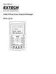
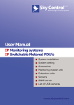
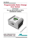
ELECTRICAL MEASUREMENT SOLUTIONS
DTS View
©1997-2005 Measurlogic Inc
10235 S. Progress Way, Unit 1
Parker, CO 80134
USA
+1 (303) 805 5252
Configuration & Monitoring
Software System
MEASURLOGIC
The DTS View Configuration &
Monitoring Software System from
Measurlogic Inc. has been developed
specifically for use with the DTS range of
electrical measurement, communications
and display products.
This Microsoft Windows™ based system
is easily installed within minutes on most
standard personal computers. In the
configuration mode, DTS View allows for
the configuration of all input and output
variables on the DTS 100, DTS 300, DTS
Plus, and DTS Display products.
DTS View also provides the user with
ease of remote configuration of the
communications parameters of the DTS
Com device.
In the monitoring mode, DTS View allows
for the real-time monitoring and logging
of user selected variables. DTS View
allows for simple remote diagnostics of
the DTS range of electrical measurement
modules and their output extender
modules for first-line maintenance and
commissioning purposes.
DTS View does not require any
specialised hardware and will run on
most standard personal computers. In
general, DTS View's user interface
makes use of standard Windows™
screens, menus and techniques, making
for simple navigation and operation. Pulldown menus, icons and help functions
make most of the operations selfexplanatory and minimises the need for
specific training courses.
DTS View Manual Rev F.
DTS 100 & DTS 300 Configuration
•
•
•
•
•
Inputs
Outputs
Serial transmission parameters
Number of measured channels
Diagnostics
•
Windows® 95, 98, NT,
2000 & XP
•
Real-time Monitoring
•
Configuration of full
range of DTS products
•
Diagnostic tool
•
User-friendly interface
•
Standard PC hardware
platform
DTS Plus Configuration
•
•
Outputs
Diagnostics
DTS Display Configuration
•
•
•
Display parameters
Nominal values
Hi and Lo alarm values
DTS Com Configuration
•
•
Communications parameters
Protocol selection
Monitoring Functions
•
•
Real-time display and logging of
up to 30 variables
Easy addition, removal and
grouping of displayed data
©Measurlogic Inc.
ELECTRICAL MEASUREMENT SOLUTIONS
Installing DTS View
The DTS View Installshield© Setup Wizard makes installation of the software easier than ever.
Before You Begin
Before you install DTS View, make sure your computer meets the following minimum system requirements:
♦
♦
♦
♦
♦
♦
486DX, 66MHz or higher processor
24MB of RAM
2MB of space available on your hard disk drive
VGA or higher resolution monitor (preferably 800 x 600)
Pointing device
Standard serial port
Running DTS View Setup
Insert the DTS View CD into your disk drive or download DTS View files from www.measurlogic.com.
Select “Start” - “Run”.
The Run dialog appears prompting for a file to Open.
Type “View1-XX.exe” and select the “Ok” button. Win-zip will run and ask for the folder to which the files will be extracted.
In the Folder selected you will find 2 sub folders called DISK 1 and DISK 2. In the DISK 1 folder select and run “setup.exe”
The Installshield© Wizard will now guide you through the installation procedure.
Running DTS View Software
To run the DTS View software, select the DTS View icon from your desktop or select “Start” - “Programs” – “Measurlogic” - “DTS View”.
Getting Started
DTS View's user interface makes use of standard Windows™ screens, menus and techniques, making for simple navigation and
operation. Pull-down menus, icons and help functions make most of the operations self-explanatory and minimises the need for
specific training courses.
Title Bar
Menu Bar
Toolbar
Main Window
DTS View Manual Rev F.
©Measurlogic Inc.
ELECTRICAL MEASUREMENT SOLUTIONS
DTS View Menu Bar
The DTS View menu bar allows the user access to the powerful features of the Configuration & Monitoring software.
File
Used to exit from DTS View.
Configure
The configuration of the attached DTS device is performed using this drop-down menu.
Configure - Inputs
The desired input parameters of an attached DTS 100 or 300 device are
configured by accessing this menu item. These include the physical
voltage and current connection, as well as the CT and VT ratio for each input.
Configure - Outputs
The desired output parameters of an attached DTS 100, 300 or Plus
device are configured by accessing this menu item. These include the
scaling of the analog or relay outputs as well as the mapping of the
required measurement parameter to the required output.
Configure - Diagnostics
The DTS diagnostic feature allows the user to make, break or pulse
any relay output as well as set any value to an analog output. This
is extremely useful in commissioning the system.
Configure - Monitors
Allows the user to add, remove and group real time on-screen variables.
A maximum of 30 variables can be displayed at one time. It also provides
for the logging of variables to a delimited text file.
Configure - Display
The user can configure the position of a selected variable on any of 3 lines
per page of information. A maximum of 8 pages are available. For each
variable, the user can configure its nominal value as well as HIGH and LOW
alarm thresholds.
Configure - Com
The desired parameters of an attached DTS Com are configured by
accessing this menu item. These include the baud rate and the device
address.
Configure - Options
The user can provide their name to be attached to print files.
!
NOTE:
Selection of any of the above
configuration functions will
result
in the relevant Configuration
dialog. No configuration of
any of the above items can
be made without the correct
DTS device connected and
its information uploaded into
DTS View.
DTS
The communication to and from an attached DTS 100 or 300 device, as well as setting up the transmission parameters, registering your
DTS View software to make use of the calibration features of DTS View, and restoring factory settings are accessed using this menu.
DTS - Upload from DTS
The parameters of an attached DTS 100, 300 or Plus
device are uploaded into DTS View.
DTS - Download to DTS
New parameters are downloaded to an attached
DTS 100, 300 or Plus device. Caution should be
exercised as this will overwrite the existing setup
profile of the attached DTS device.
DTS View Manual Rev F.
©Measurlogic Inc.
ELECTRICAL MEASUREMENT SOLUTIONS
DTS - Transmission Setup
The desired serial port and setup is configured by selecting this menu item. The default is a baud rate of 9600, no parity,
8 data bits and 1 stop bit.
DTS - Registration
Allows for the registration of DTS View to make use of its powerful calibration features.
DTS - Restore Factory Defaults
Allows the user to restore factory default settings for an attached DTS device.
DTS – Query Talk Version
Allows the version of DTS Talk protocol to be identified for an attached DTS device.
DTS – Password
Allows the user to specify a password preventing unauthorized persons from altering DTS configurations.
View
Used to toggle toolbar and status bar on and off.
Help
DTS View About screen and help.
DTS VIEW TOOLBAR
Visual button style access to the most important DTS View menu bar functions.
The parameters of an attached DTS 100, 300 or Plus device are upload into DTS View.
New parameters are downloaded to an attached DTS 100, 300 or Plus device.
CAUTION: This could result in the configuration of the attached DTS device to be changed.
The desired input parameters of an attached DTS 100 or 300 device, are configured by
selecting this button.
The desired output parameters of an attached DTS 100, 300 or Plus device are configured
by selecting this button.
DTS View Manual Rev F.
©Measurlogic Inc.
ELECTRICAL MEASUREMENT SOLUTIONS
Allows for the configuration of on-screen monitors and logging by selecting
this button.
Allows the user to set the status of any relay output as well as set a value of any analog
output. Factory Configuration might be available depending on user rights.
The desired parameters of an attached DTS Display are configured by selecting
this button.
The desired parameters of an attached or internal DTS Com are configured by
selecting this button.
Reveals the type of DTS device attached to the system.
Displays the DTS View About screen and system configuration as depicted below.
MEASURLOGIC
Provides On Line HELP with DTS View
DTS View Manual Rev F.
©Measurlogic Inc.
ELECTRICAL MEASUREMENT SOLUTIONS
Configuring a DTS 100, 300 or Plus
Before You Begin Configuration
Ensure that a DTS device (DTS100 or 300 with/without DTS Plus)
is connected to your PC with the correct communications cable.
The attached DTS devices should have an auxiliary supply
connected and the Power LED indicating an “on’ condition.
It is essential that you Upload from DTS to be able to configure the
attached device. Should you not upload from DTS prior to accessing
any of the Configure menu items or toolbar buttons, DTS View will not
allow the entry of any parameters. DTS View will Inform you of a
completed upload.
Configuring DTS 100/300 Inputs
Select Inputs from the drop-down menu or the Configure Inputs toolbar button. The DTS Input Configuration dialog appears.
The dialog contains four tabs namely Channel 1, Channel 2, Channel 3 and 3 Phase Settings. The first three tabs are identical and
each represents an individual input channel on the connected DTS. In the case where an upload was performed from a connected DTS
100, only channel 1 becomes available for configuration, while the remaining two channels are selectable but completely disabled. If an
upload was performed from a DTS 300 all three channels are enabled for configuration. The 3 Phase Settings tab allows the toggle
between Line-Neutral or Line-Line display of voltages.
Each channel tab contains a Name field, which could be used for a descriptive text string up to a maximum of 20 characters. It further
contains two frames, one for the Voltage Input and another for the Current Input.
DTS View Manual Rev F.
©Measurlogic Inc.
ELECTRICAL MEASUREMENT SOLUTIONS
Voltage and Current Input frame:
Voltage phase selection is done from within the Phase combo box shown below.
In the case where a voltage input is not required, this parameter can be specified as Not Connected. It can also be selected as
Independent in which case the same selection should be made for the current phase. Independent measurement refers to a
measurement system where the voltage and current input sources are unrelated.
The remaining options are used to describe the phase relationship between the connected voltage and current for that particular
channel. Here it is of utmost importance to specify the correct phasing relationship in order for the system to calculate the correct power
and energy values.
V[an], V[bn] and V[cn] refers to phase-to-neutral voltages for phases A, B and C respectively. V[ab], V[bc] and V[ca] refers to phase-tophase voltages (line voltages) constructed from the addition of phasors V[an]/V[bn], V[bn]/V[cn] and V[cn]/V[an] respectively.
It is important to realise that the voltage and current inputs for each channel in the input configuration dialog is associated with an input
pair on a DTS 300 for instance. In other words, channel 1’s voltage and current inputs are referring to physical inputs V1 and I1 on the
DTS device. Similarly channel 2’s voltage and current inputs are associated with physical inputs V2 and I2 on the DTS 300.
To give an example, suggest that a DTS 300 device was connected in WYE with V1 accepting phase A and phase B voltages in that
order, V2 accepting phase B and phase C voltages and V3 accepting phase C and phase A voltages, again in that order. The correct
voltage phasing setup for this configuration would be to select V[ab] for channel 1’s voltage input, V[bc] for channel 2 and V[ca] for
channel 3.
Similarly, the current input phasing is done from the Phase combo box within the Current Input frame. The same rules apply for the
current phasing than does for the voltage. DTS would even allow for the measurement of delta line currents, and here the correct
phasing selection would be I[ab], I[bc] or I[ca].
The system can further be configured for any voltage/potential transformer (VT/PT) and current transformer (CT) ratios. Simply uncheck
the relevant Coupled Directly checkbox and supply the VT/PT and CT ratio values. Where a combo box is available one of the standard
values can be selected or any custom value can be entered. The primary voltage must be specified in 100 V units. In other words, the
program will round an entry of 123456 V to 123,5 kV.
Secondary voltage can be entered in 1 V units, while primary and secondary currents are entered in 1 A units.
DTS View Manual Rev F.
©Measurlogic Inc.
ELECTRICAL MEASUREMENT SOLUTIONS
Open existing template
Save template
Save template with a new name
Print template
Configuring DTS 100/300 or Plus Outputs
Select Outputs from the Configure drop-down menu or the Configure Outputs toolbar button.
The DTS Output Configuration dialog appears. At this point it is assumed that a successful upload has been performed from the
attached DTS device. In case you wish to make alterations to the configuration of one or more DTS Plus devices, these devices have
had to be connected to a DTS 300 device and powered before the upload from the DTS 300 was performed (Refer to the DTS Plus
user manual for details on how to connect DTS Plus devices to a DTS 300 device).
The DTS Output Configuration dialog contains twelve possible physical outputs, each with an associated configure button. These
outputs appear as combo-boxes and are normally disabled to the user. The option shown in each is the factory fitted configuration and
cannot be altered by the user. One of four different cases will apply to each output slot:
1)
2)
3)
4)
“Analog Output” – the factory configuration for the particular output slot was for an output of the analog type.
“Relay Output” – the factory configuration for the particular output slot was for an output of the relay type.
“Not Available” – no output was installed in the particular slot.
Blank box – A virtual slot was not found for the particular output. In the case of a DTS100 only the first four output slots
actually exist. The remaining eight slots would appear blank.
DTS View Manual Rev F.
©Measurlogic Inc.
ELECTRICAL MEASUREMENT SOLUTIONS
Configuring an Analog Output
To configure any available analog output, click on its associated configure button in the DTS Output Configuration dialog.
The dialog displays the currently selected entity and phase information, minimum and maximum engineering values and their
corresponding output values, a nominal output range selection, and a checkbox labelled Secondary.
DTS View Manual Rev F.
©Measurlogic Inc.
ELECTRICAL MEASUREMENT SOLUTIONS
The range setting gets factory set to the customers’ requirements and is disabled under normal conditions. The value given for the
range indicates the nominal output value and also the type of output: current (mA) or voltage (V).
The first step in configuring or re-configuring any output is to select the required input (measured) entity for the operation. Click on the
Change button inside the Entity frame. The Entity Selection dialog appears.
For analog outputs only current, voltage, frequency, power factor, and all power entities are available for selection. These are all nonaccumulative entities. Once the required entity has been selected, the user must specify which phase (if multiple phases are available)
is to be assigned to the output. Once this has been done, click on O.K. The new entity and phase info is now displayed in the Analog
Configuration dialog.
DTS View will provide default values for minimum and maximum engineering values. The maximum value is based upon the nominal
voltage and current input ranges, assuming unity power factor. For frequency the default minimum and maximum values are 45Hz and
55Hz respectively.
The user can edit these values by clicking inside the appropriate box and typing the new value in base units, or kilo/mega units where
scaling is performed in primary units. Take care when typing minimum and maximum values. First confirm the status of the Secondary
checkbox. If this box is checked, minimum and maximum values must be given as secondary quantities. If this is not done it will result
in massive scaling errors. Next select the corresponding analog output values from the respective combo boxes.
If the scaling was done in secondary units (Secondary checkbox checked), uncheck the Secondary checkbox to confirm the correct
primary value scaling. Once you are satisfied with the configuration, click on the O.K. button in the top right hand corner of the
Configure Analog Output dialog. DTS View returns to the DTS Output Configuration dialog. If you wish to configure another analog
output click on its corresponding configure button. If you are done configuring outputs, close the DTS Output Configuration dialog in
the bottom left hand corner.
NOTE
Remember, settings will only take effect once a successful download has been performed to the attached DTS device.
Configuring a Relay Output
To configure any available relay output click on its associated configure button in the DTS Output Configuration dialog.
The dialog displays the currently selected entity and phase information. The dialog further contains a threshold and pulse section. If any
non-energy entity is selected (voltage, current, power etc.), the threshold output section is automatically enabled and the pulse output
section is disabled. If an energy entity is selected, DTS View disables the threshold section and enables the pulse output section.
Click on the change button inside the entity frame. The Choose Measuring Entity dialog appears. For relay outputs all possible
entities are available for selection. Make the required entity and phase selection and click on the O.K. button. The new entity and phase
information is displayed.
Configure threshold relay outputs
DTS View Manual Rev F.
©Measurlogic Inc.
ELECTRICAL MEASUREMENT SOLUTIONS
If any non-accumulative entity was selected, DTS View enables the threshold output section. A threshold value can be specified in
either primary or secondary units (check status of Secondary Values checkbox), together with a percentage hysteresis. The hysteresis
value is taken as a percentage of the threshold value and not the nominal output value. The user can further specify the method of
triggering, as either rising or falling edge.
The solid-state relay present inside the DTS device has only one contact. Triggering will energise the relay causing an approaching
short-circuit of the particular output contact pair on the DTS device.
In case of a rising edge configuration, the relay will energise when the measured value exceeds the specified threshold value. The relay
will de-energise once the measured value drops below the specified threshold value less the specified percentage of the threshold
value.
In case of a falling edge configuration, the relay will energise when the measured value first drops below the specified threshold value.
The relay will de-energise once the measured value exceeds the specified threshold value plus the specified percentage of the
threshold value.
Configure pulse relay outputs
If any accumulative entity was selected (energy), DTS View enables the pulse output section. A power value (active, apparent or
reactive) can be specified in either primary or secondary units (check status of Secondary Values checkbox), together with a pulsesper-hour pulse rate. In other words, the system is provided with a quantity of power, which is equated to a number of pulses in a
specified time.
To put this into perspective let’s look at an example. Suggest that the pulse output was configured for 1 kW and 3600 pph (pulses-perhour). The system is started and the pulse counter is reset to zero. Now you apply exactly 1 kW to the inputs for exactly 1 hour. The
reading on the counter after one hour would be 3600. To convert this to kWh, simply divide the number of pulses, at any point in time,
by 3600. Let’s say that the input power is reduced to 500 W after one hour, and kept at that level for another hour. After this hour the
counter total would be 3600 + 1800 = 5400. Take the total count and divide by 3600 to yield 1.5 kWh.
Alternatively, if the configuration parameters provided an energy per pulse specification, say one pulse equals 0.3 Wh of energy, the
following conversion needs to be done to configure the pulse output correctly:
Energy-per-pulse = 0.3Wh
Power
= Energy-per-pulse * pph (choose pph as 3600 or less)
= 0.3Wh * 3600
= 1080W
= 1.08kW
DTS View Manual Rev F.
©Measurlogic Inc.
ELECTRICAL MEASUREMENT SOLUTIONS
OR
Power
= Energy-per-pulse * pph
= 0.3Wh * 1800
= 540W
Both of the above configurations will yield the same result. In the case of 3600 pph specified, the proportional power quantity must be
1.08kW to achieve 0.3Wh per pulse. In the case of 1800 pph specified, the proportional power quantity must be 540W to again achieve
0.3Wh per pulse.
Configuring of DTS monitors and logging:
Select Monitors from the Configure drop-down menu or the Configure Monitors toolbar button.
The DTS Configure Monitoring dialog appears. Once again it is assumed that a successful upload has been performed from the
attached DTS device.
The dialog contains a list of already monitored entities, add and remove buttons, display positioning buttons, and open- and close log
buttons. If monitors were previously set up for a particular installation of DTS View, these monitors will re-appear on the screen after the
first successful upload from a DTS 300 or DTS 100. Any non-relevant or invalid monitors for the upload will be removed automatically.
Adding entities to be monitored
To add an entity to the list to be displayed, simply click on the Add button in the Configure Monitoring dialog. The Choose
Measuring Entity dialog appears. Select the electrical entity from the list of available entities and specify a phase. Click on the Add
button next to the Close button. Repeat this process for all the required entities. Once done, click on the Close button to return to the
Configure Monitoring dialog. The new list of entities is displayed.
To rearrange the selection of entities, click on a particular entity to highlight it, and then scroll it to the required position in the list using
the up/down arrow buttons on the dialog.
Removing entities already being monitored
Select an individual entity by clicking on its description in the list. The selection is highlighted. Click on the Remove button to remove
the entity from the list. To select and remove more than one entity in one operation, click on the first entity and drag the cursor down to
the last entity to be removed. The entire range of entities is highlighted. Click on the Remove button to remove the selected entities.
DTS View Manual Rev F.
©Measurlogic Inc.
ELECTRICAL MEASUREMENT SOLUTIONS
Opening and closing of logging files
To start a log file in the Configure Monitoring dialog, pre-select the monitors to be logged. Only selected monitors will be logged. By
clicking on the Open Log button, the user specifies an already existing log file for overwriting, or a new file name. Select an appropriate
logging interval in seconds and click on the OK button. Logging to a semicolon delimited text file will commence once all dialogs are
closed.
To terminate the logging process, simply open the Configure Monitoring dialog and click on the Close Log button. The file is closed
and can now be accessed by other programs for analysis and processing.
DTS View Manual Rev F.
©Measurlogic Inc.
ELECTRICAL MEASUREMENT SOLUTIONS
Should you wish to monitor the secondary values on-screen, simply check the Show Secondary Values check box that appears below
the on-screen monitors.
Typical on-screen monitor displaying the secondary values
The Status Bar at the bottom of the screen indicates the communications status between DTS View and the attached DTS device.
An LED labelled COMMS changes from green to red depending on the communications status. Green representing communication
between DTS View and an attached DTS device while red indicates a communications break.
Communication OK
Communication Break
DTS View Manual Rev F.
©Measurlogic Inc.
ELECTRICAL MEASUREMENT SOLUTIONS
Configuring DTS Display
Before selecting Display from the Configure drop-down menu or the Configure DTS Display toolbar button, ensure that the DTS
Display has been connected to the proper serial port on your PC. By selecting one of these options, an “upload” is effectively performed
from the display.
The DTS Display Configuration dialog appears. At this point the dialog will display the current setup of the connected DTS Display.
Any parameter can now be edited, or the user can open an existing template (see section on DTS Templates) for download to the
display.
Scroll through the up- and down-arrows in the Select Current Page & Line frame to select a preferred page and line to be edited. In
the Layout for the Current Page & Line frame, select the preferred Channel. One to three represents an actual input channel on a
DTS device. For a DTS Display to be connected to a DTS 100, only channel 1 can be used. For a DTS 300, all three channels and the
3-phase virtual channel apply. Select the value to be displayed as either secondary or primary from the Display Value drop-down box.
To configure the way in which a particular value is displayed, the correct combination of Units and Decimal Point must be selected. If
units are specified as kilo it would result in a scaling factor a thousand times smaller than when base units are specified. For example,
if the primary voltage is to be displayed, lets say 11000V, with units selected as V the displayed value will be 11000 V with a decimal
point specified as (0.). If units were specified as kV, the displayed value will be 11.00 kV with a decimal point specified as (0.00).
Any nominal, low and high values can be specified as long as they make sense logically. These values are merely for indicative
purposes and if any of the high and low conditions are met, the DTS-Display will merely give a visual indication to the operator by
displaying the variable in reverse video mode.
Use can be made of a previously saved display template for configuration, or the user can save a just-configured template for future
use.
Once satisfied with the entire configuration, simply click on the OK button to perform a download to the attached DTS-Display device.
DTS View Manual Rev F.
©Measurlogic Inc.
ELECTRICAL MEASUREMENT SOLUTIONS
Configuring the Communication Parameters
The Communication parameters can be configured via DTS View depending on the specific configuration of DTS 100 or 300 ordered.
For the DTS 300 device the communications port is built into the device and can be configured by selecting Com from the pull-down
menu Configure. It can also be configured using the DTS Com icon on the toolbar. In the case of a DTS 100 device, the
communications port is in the DTS Com module which is separate from the DTS 100. With The DTS Com module connected to the
DTS 100 it can be configured by selecting Com from the pull-down menu Configure. It can also be configured using the DTS Com icon
on the toolbar.
The DTS Com Configuration dialog is now displayed.
The Unit ID, Attached device, Baud rate, Parity, Data Bits, Stop bits, Handshake as well as the required protocol can be selected and
modified in the dialog.
Once configured, download the new configuration by clicking on the OK button.
DTS View Manual Rev F.
©Measurlogic Inc.
ELECTRICAL MEASUREMENT SOLUTIONS
Contact Details
Measurlogic Inc., synonymous with the design and
manufacturing of electrical measurement systems for the past
30 years, introduces a flexible and fully configurable range of
new generation, digital electrical measurement solutions.
Measurlogic has a long and proven track-record of
manufacturing, providing and supporting high quality analog
electrical measurement products and has rightly been
recognised as a world leader in this field.
Measurlogic Inc. can also provide a complete range of power
monitors, electrical transducers, Power Quality Recorders and
Analyzers as well as the DPI and VDC range of Voltage Dip
Proofing Inverters.
DTS is a family of products which caters for all electrical
measurement applications - from the most simple single-phase
measurements to the most advanced multi-phase monitoring
and control applications. DTS provides for the needs of all
users in all applications - from the power supply industry to
power users, from energy management consultants to system
planners, from managers to engineers, from maintenance
technicians to project leaders, from refurbishment of existing
plants to new installations.
Note : Information and specifications in this document are subject to change at
any time.
MEASURLOGIC INC.
10235 S. Progress Way, Unit 1
Parker, CO 80134, USA.
TEL: +1 (303) 805 5252
FAX: +1 (425) 799 4780
e-mail:
website:
[email protected]
www.measurlogic.com
Represented by :
DTS View Manual Rev F.
©Measurlogic Inc.