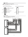
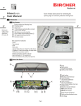
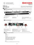
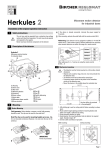
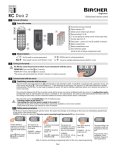
1
EN ISO
9001
This product meets or exceeds
ANSI standard 156.10 as independently
tested by TÜV Rheinland North America
Quality
1”
international
level
PrimeTec
User Manual
2”
1
Combined microwave (motion)/active infrared (safety) sensor
for activating and protecting automatic pedestrian sliding doors
Introduction
1.1 Box Contents
D
EN ISO
9001
3”
This product meets or exceeds
ANSI standard 156.10 as independently
tested by TÜV Rheinland North America
Quality
international
level
Combined microwave (motion)/active infrared (safety) sensor
for activating and protecting automatic pedestrian sliding doors
3”
0641&7%6+10
Box Contents
EN ISO
9001
Quality
international
level
This product meets or exceeds
ANSI standard 156.10 as independently
tested by TÜV Rheinland North America
Combined microwave (motion)/active infrared (safety) sensor
for activating and protecting automatic pedestrian sliding doors
0641&7%6+10
A
B
C
Box Contents
The box contains the following items:
Markings for
safety curtain
adjustment
(See page 6)
Markings for
safety curtain
adjustment
(See page 6)
E
Markings for
safety curtain
adjustment
(See page 6)
E
PrimeTec sensor
Sensor cover
Click-in safety curtain masking covers (2)
Instruction manual
Self-tapping mounting screws (2)
10’ (3 m) 8-wire electrical cable to connect
sensor to door operator
N ISO
9001
Qu l y
ternational
le el
Parts of the Sensor
This product meets or exceeds
ANSI standard 156.10 as independently
tested by TÜV Rheinland North America
Combined microwave (motion)/active infrared (safety) sensor
for activating and protecting automatic pedestrian sliding doors
0641&7%6+10
Box Contents
Marking for
safety curtain
adjustment
(See page 6)
The box contains the following items:
PrimeTec sensor
Sensor cover
10’ (3 m) 8-wire electrical cable to connect
sensor to door operator
Self-adhesive mounting template
Click-in safety curtain masking covers (2)
Self-tapping mounting screws (2)
Instruction manual
Tools required for installation:
- Ladder
- Tape measure
- Level
- Wire cutter
- 4 gauge (5 mm dia.) wire stripper for cable sleeve
- 26 gauge (0.14 mm²) wire stripper for single wires
- Phillips head screwdriver (size #1)
- Flathead screwdriver 1/8” (#1/ 3.6 mm)
- Electric drill with 1/2” (12 mm) drill bit
- Electric screwdriver with phillips head (size #2)
Pa ts of the Sensor
Self-adhesive mounting template
Tools required for installation:
- Ladder
- Tape measure
- Level
- Wire cutter
- 4 gauge (5 mm dia.) wire stripper for cable sleeve
- 26 gauge (0.14 mm²) wire stripper for single wires
- Phillips head screwdriver (size #1)
- Flathead screwdriver 1/8” (#1/ 3.6 mm)
- Electric drill with 1/2” (12 mm) drill bit
- Electric screwdriver with phillips head (size #2)
PrimeTec Self-Adhesive Mounting Template
Screw
Sc ew
Align with center of door header
D a. 1/2” (12 mm) for cable exit
PrimeTec sensor
Sensor cover
Click-in safety curtain masking covers (2)
Instruction manual
Self-tapping mounting screws (2)
10’ (3 m) 8-wire electrical cable to connect
sensor to door operator
PrimeTec sensor
Sensor cover
Click-in safety curtain masking covers (2)
D Instruction manual
E Self-tapping mounting screws (2)
F 10’ (3 m) 8-wire electrical cable to connect
sensor to door operator
Self-adhesive mounting template
PrimeTec Self-Adhesive Mounting Template
Screw
Screw
Align with center of door header
Dia. 1/2” (12 mm) for cable exit
Tools Required for Installation
- Ladder
- Tape measure
- Level
- Wire cutter
- 4 gauge (5 mm dia.) wire stripper for cable sleeve
- 26 gauge (0.14 mm²) wire stripper for single wires
- Phillips head screwdriver (size #1)
- Flathead screwdriver 1/8” (#1/ 3.6 mm)
- Electric drill with 1/2” (12 mm) drill bit
- Electric screwdriver with phillips head (size #2)
Parts of the Sensor
C
S
4”
B
F
G
A
PrimeTec Self-Adhesive Mounting Template
Screw
G
Self-adhesive mounting template
Screw
Align with center of door header
Dia. 1/2” (12 mm) for cable exit
Ali
ith b ttom f d
h d
1.2 Tools Required for Installation
5”
- Ladder
- Tape measure
- Level
- Wire cutter
- 4 gauge (5 mm dia.) wire stripper for cable sleeve
- 26 gauge (0.14 mm²) wire stripper for single wires
- Phillips head screwdriver (size #1)
- Flathead screwdriver 1/8” (#1/ 3.6 mm)
- Electric drill with 1/2” (12 mm) drill bit
- Electric screwdriver with phillips head (size #2)
1.3 Parts of the Sensor
A Cover
B Safety sensor
A
C
B
C
D
Motion sensor
indicator LED window
E
Cable bushing
Mounting screw holes (2x)
Cable connector
(for new installations)
Screw terminals
(for retrofit installations)
Active infrared safety curtain lens
(safety sensor)
Safety sensor indicator LED (red)
Red button (function)
Black button (value)
Motion sensor indicator LED (green)
F
D
G
E
H
F
I
J
K
L
M
F
G
H
I
J K
L M
N
O
P
N
O
P
Page 1
indicator LED window
Safety curtain window
Safety curtain adjustment screw
Microwave module (motion sensor)
LCD display
2
Safety Precautions
2.1 General Safety
Warning: failure to follow these safety precautions may cause damage to sensor or objects, serious personal injury, or death.
-This product is designed to be mounted on the header of an automatic sliding or telescopic door.
-Do not use this product other than for its specified application.
-Observe all local, national, and international door safety standards, codes, and laws.
-Only trained and qualified personnel may install and initialize the sensor.
-Only authorized Bircher Reglomat personnel may perform hardware/software changes or repairs to the product.
-The unit should only be operated from a safety extra low voltage (SELV) system with safe electrical separation.
-Always consider the safety functions of your applications as a whole, never just in relation to one individual section of the system.
-The installer is responsible for testing the system to ensure it meets all applicable safety standards (e.g. ANSI 156.10).
-Never touch any electronic components or lenses.
2.2 Installation Safety
-Follow all steps outlined in this manual in order for proper installation of the product.
-Stop all pedestrian traffic through the door before installing sensor.
-Ensure there is no pedestrian traffic through the door until sensor is installed and tested for compliance with all applicable safety standards
(e.g. ANSI 156.10).
-Verify proper installation of door equipment before installing sensor.
-Shut off all power before attempting any wiring procedures.
-Always use wire terminals to terminate stranded wire ends.
-Check placement of wiring to ensure moving parts are not impeded by wires.
-Make sure wiring is correct before applying power to the sensor to avoid damage to equipment.
-Ensure door & header coverplate are properly grounded to protective earth (PE).
-Ensure (e.g. by walk testing) that installation is in compliance with all applicable standards (e.g. ANSI 156.10) after completion of installation.
-If the sensor sustains damages (e.g falls), replace it with a new unit.
-If a satisfactory solution cannot be achieved after troubleshooting a problem, please call Bircher Reglomat at 800-252-1272 or
visit our website at www.bircherreglomat.com.
DO NOT LEAVE ANY PROBLEMS UNRESOLVED! DO NOT SACRIFICE SAFETY FOR ANY REASON!
3
Mounting the Sensor
3.1 Special Considerations
Ensure door header coverplate is always in place and
held tightly by screws.
Mount the PrimeTec rain
cover, (PTCR) if sensor is
exposed to rain.
Obstruction can affect
performace. Ensure safety
& motion sensors have
unobstructed views.
3.2 Removing the Cover
Grasp cover firmly and insert one finger
beneath the mounting screw holes on the
sensor baseplate. Pull the sensor toward
you to remove the cover.
To remove cover once the sensor is
mounted on the door frame, grasp the
cover firmly on either side and pull toward you.
Page 2
Mount sensor away from
fluorescent or HID light
sources.
3.3 Wiring the Sensor
New installation using gray cable
with plug
Insert the female plug on the gray
cable into the male receptacle on the
sensor. Ensure the plug is fully inserted.
Proper insertion of the cable
connector into receptacle
Retrofit installation using
detachable screw terminal
The cable will only fit into the receptacle if the grooves are lined up
properly. Do not force the connector into the receptacle or
damage could result.
Shown above is the 4-wire retrofit
wiring scenario using the detachable screw terminal. Insert the
proper wires into terminal (based
on the wiring diagram on page 4)
and tighten the screws with a 1/8”
flathead screwdriver.
Important note: for both options, slide the cable into the cable bushing to hold it firmly in place.
Use of the cable bushing is important to prevent water from seeping into the sensor.
3.4 Routing the Cable (for retrofit installations with existing cable hole)
Route the cable in the cable channels so it is flush against the back of the sensor.
Several options are shown- select the best option for your installation.
3.5 Positioning & Attaching the Sensor
Middle of door opening
PrimeTec Self-Adhesive Mounting Template
Screw
Screw
Align with center of door header
Dia. 1/2” (12 mm) for cable exit
Align with bottom of door header
= Cable feed space
Template
MT-PT 0611
-1” / + 3” tolerance
Maximum mounting height = 13’ (4 m)
1. Position the removable self-adhesive mounting template on
the door header frame in the middle of the opening (see illustrations) Ensure template is level on the door header frame
and the bottom of the template is aligned with the bottom of
the door header frame (-1” / + 3” tolerance).
2. Drill hole for cable in marked location using 1/4” drill bit for
cable only or 1/2” for cable + connector.
Double
ouble sliding door
Single sliding door
3. Using an electric screwdriver, insert self-tapping screws in
marked location. Torque rating is 3.7 ft-lb (5 Nm).
4. Remove the mounting template.
5. Attach sensor to screws and tighten to hold the sensor
firmly on the door header frame.
Page 3
4
Electrical Connections
4.1 4-Wire Connection: Standard Option (Combined motion & safety outputs)
New installation using gray cable with plug
Cable
Retrofit installation using detachable screw terminal
Black
Red
11.5 - 36 VDC/
10 - 28 VAC
Power
White
Green
COM
NO
Motion/
Safety
Power
11.5 - 36 VDC/
10 - 28 VAC
COM
NO
4.2 6-Wire Connection: Recommended Option (Enhanced performace through separate motion & safety outputs)
Sensor must be programmed for this wiring configuration.
Press and hold the black value button for 8 seconds to separate motion & safety outputs.
For more details, please see section 8.
This option may only be used with the included gray cable.
Black
11.5 - 36 VDC/
10 - 28 VAC
Red
Cable
Power
White
COM
NO (NC)
Green
Motion
Brown
+
Blue
COM
NO (NC)
Safety
Check for correct polarity
4.3 8-Wire Connection: Best Option (Additional safety through monitoring)
Monitoring function is self-configurating and will be active as soon as unit is powered on if the following wiring is used.
May not be available for all door operators.
Sensor must be programmed for this wiring configuration.
Press and hold the black value button for 8 seconds to separate motion & safety outputs.
For more details, please see section 8.
This option may only be used with the included gray cable.
Black
11.5 - 36 VDC/
10 - 28 VAC
Red
Power
White
COM
NO (NC)
Green
Cable
Brown
Blue
+
Motion
COM
NO (NC)
Safety
Check for correct polarity
Orange
Yellow
+
Monitoring
Page 4
Check for correct polarity
Motion/
Safety
5
Initialization
Green LED
(Motion)
Red LED
(Safety)
REMOVE all foreign OBJECTS that are not part of the normal
door system environment BEFORE powering on the sensor.
Make sure no people or moving objects are in the door area,
otherwise correct startup will not be possible.
The alternate flashing LED’s indicate the initialization (teach-in) of the sensor.
(Duration 10 - 15 sec.) The LED’s will then remain continuously lit for 10 more
seconds. Please see below for LCD screen readouts.
The door system is now operational at this point.
The safety/motion LED’s will only illuminate when a detection occurs.
If using combined outputs (standard), the green LED will illuminate together with
the red LED when a safety detection occurs.
6
Screen during
initialization
Screen after
initialization
Safety Curtain Adjustment
6.1 Adjusting the Safety Curtain Width
The width of the safety curtain can be adjusted by clicking in the plastic masking cover in front of the sensor lens.
Safety Curtain Dimensions
Rule of thumb: field width is approximately equal to
mounting height.
Sensor without masking cover: full pattern size (factory setting)
Field width: approx. 6’6” (2 m) at 7’ (2.1 m) mounting height
Field depth: approx 8” (.2 m) for 2 rows
Possible safety curtain width settings
The field size varies depending on which sections of the lens are masked by the click-in covers.
Red button
A
B C
D
A
B
C
D
A
B
C
D
A
B
C
D
A
B
C
Adjusting the safety curtain width using click-in masking covers
Location of safety curtain
masking covers inside sensor
cover
Insert masking cover in slot
below lens
Click into place
Page 5
Location of slot below lens
D
6.2 Adjusting the Safety Curtain Distance from the Door
– +
7°
Please refer to current published
ANSI standard for exact measurements.
The built-in self-monitoring could
malfunction or indicate an error if
the safety curtain is angled too far
away from the door panel.
For troubleshooting, please see
section 9.
7
For assistance, use the measuring guide on the front of the
manual to determine this
distance.
2° (factory setting)
0°
-5°
1/8 turn » 1° » 1”
Hold the guide no more than
10” (25 cm) off the ground and
move it from the door opening
into the safety field until the red
LED illuminates.
1° of adjustment (1/8 or 45° turn with a
screwdriver), is approximately equal to 1”
of curtain movement on the floor.
Factory setting = 2°
Motion Sensor Adjustment
7.1 Changing the Motion Field Pattern
The motion field pattern can be changed by rotating the microwave module.
Standard Field
Narrow Field
1
Release the side clip
by hand or with a
screwdriver
2
Rotate
3
Standard field microwave
module poition
Push module into place
until it clicks
Page 6
Narrow field microwave
module poition
7.2 Adjusting the Motion Field Size to Meet Standard Requirements
In order to meet ANSI standard 156.10, the sensor’s
motion field pattern must cover the ANSI-specified field
dimensions (designated by x’s in the drawing).
Please refer to the current published ANSI standard for
details.
7.3 Motion Field Dimensions
Narrow Field
7’ (2.1 m)
7’ (2.1 m)
Standard Field
0 ft
ft
ft
0 ft
3 ft
ft
ft
3 ft
0 ft
ft
6 ft
ft
6 ft
ft
3 ft
ft
9 ft
ft
9 ft
ft
6 ft
ft
ft
9 ft
0 ft
ft
12 ft
ft
3 ft
ft
Minimum Field Size: W x D = 20” x 10” (0.5 x 0.25 m)
Maximum Field Size: W x D = 13’ x 6’ 6” (4 x 2 m)
Measured at 30° angle
Minimum Field Size: W x D = 6” x 30” (0.16 x 0.8 m )
Maximum Field Size: W x D = 6’ 6” x 13’ (2 x 4 m)
Measured at 30° angle
Rule of thumb: The width:depth ratio of the motion field is approximately 2:1 (standard field) or 1:2 (narrow field)
Field size changes with mounting height.
7.4 Placement of Motion Field
Inclination
-5° to 90° in 5° increments
Pivot
-20° to 20° in 5° increments
Factory setting: 20° (5 clicks up from end)
Factory setting: 0°
+
–
–
+
+
–
–
Page 7
+
8
Configuration (Operator Buttons)
8.1 Entering Configuration Mode
Red button
LCD panel location
Black button
1
Start in
automatic
mode
Shortly press
the red
&
black buttons
simultaneously
to enter configuration mode.
Once in configuration mode, the circled number in the
LCD display will
start to blink. Press
the red button until
you reach the desired function block.
1
Once in the desired fun- Once all changes End in
ction block, press the are complete, automatic
red button to browse press the red & mode
through the options. black buttons
Functions
Use the black button to simultaneously
Press the black button change the value. twice to return to
to select the function
automatic mode.
block shown in the dis- Selections are saved
play.
immediately.
Sensor returns to automatic mode in
60 seconds if no action is taken.
1 = Motion Functions
2 = Safety Functions
1 2 = General
8.2 Motion Sensor Settings
Motion Functions
Function
(Select with
RED button)
Field Size/Sensitivity
1
Direction Recognition
2
1
Cross Traffic Optimization
(CTO)
4
LCD
1
1
1
Values
Description
(Select with
Factory settings in bold with *
BLACK button)
1-5
1 = Smallest field
4 = Standard field*
5 = Largest field
1, 2
1 = Off (traffic both ways activates
sensor)
2 = Towards sensor only*
1, 2
1 = Off*
2 = Masking of cross traffic
(to reduce unwanted openings
from people walking by the door)
1, 2
1 = Off*
2 = On (keeps door open after initial
activation for people
hesitating/pausing before
reaching the safety curtain)
1, 2
1 = Filter off*
2 = Filter on
for EM interference, fluorescent
.......tubes, door movement, etc
(section 9.1)
1
Slow Motion Detection .(SMD)
5
1
Interference Filter
6
Output Logic
7
1 = NO*
1
1, 2
2 = NC
Page 8
8.3 Safety Curtain Settings
Safety Functions
2
Function
(Select with
RED button)
LCD
Values
Description
(Select with
Factory settings in bold with *
BLACK button)
2
1
Sensitivity
2, 3
2 = Regular sensitivity*
3 = Snow mode
1-5
1 = 10 seconds
2 = 30 seconds*
3 = 60 seconds
4 = 180 seconds
5 = 15 minutes
Teach-In Time
The amount of time until
the sensor recognizes a
motionless person/object in
the safety curtain field as
part of the background
2
2
1 = NO*
2
3
Output Logic
1, 2
2 = NC
8.4 General Settings
General Settings
1 2
Function
(Select with
RED button)
LCD
Values
Description
(Select with
Factory settings in bold with *
BLACK button)
1 2
Combined/separate outputs
2
LCD after using
shortcut:
1, 2
1 = 4-wire configuration*
(combined outputs for motion
& safety)
2 = 6-wire configuration
(separate outputs for motion
& safety)
Shortcut: Press & hold black
button for 8 seconds to separate
motion & safety outputs
Frequency of safety curtain
Can be changed to prevent
cross-talk from two sensors
on the same door (e.g. very
wide door)
1 2
3
1, 2
1 = Frequency 1*
2 = Frequency 2
Please note: some settings may not meet all applicaple standards (eg. ANSI 156.10). Please see page 2 for more details.
Ensure (e.g. by walk testing) that installation is in compliance with all applicable standards (e.g. ANSI 156.10)
after completion of installation.
8.5 Restarting the Sensor
To restart the sensor, press & hold the red button for 1 second. This is equivalent to recycling power
(powering down the sensor and up again).
8.6 Factory Reset
To reset the sensor to factory defaults settings, press & hold both red & black buttons simultaneously for 8 seconds.
Page 9
9
Troubleshooting
9.1 Remedying False Tripping
Red LED
(Safety)
Green LED
(Motion)
Fault
Remedy
1. Ensure door header coverplate is in place and held.tightly by screws.
Off
On
2. Set angle of microwave further away from door (section 7.4).
Door reverses while closing
3. Reduce microwave field size/sensitivity (section 8.2).
1. Make sure there are no moving objects such as plants, etc in
.....the vicinity of the sensor.
Off
Opening signal without
apparent external influence
On
2. Mount sensor away from fluorescent or HID light sources.
3. Direct microwave module away from other microwave
sensors in the area (section 7.4).
4. Activate filter (section 8.2).
1. Ensure door header coverplate is in place and held.tightly by screws.
2. Move door manually.
If sensor sees door:
1
On
On
1
Door reverses while closing
- Set angle of safety
curtain further away
from door panel
(section 6.2).
If sensor does not see door but
problem persists (ie. experiencing EM disturbance):
- Reduce sensitivity of the IR safety
curtain (snow mode) (section 8.3).
- Use separate power supply for
The built-in self-monitoring
sensor & door operator. Ensure
could malfunction or indicate
an error if the safety curtain is it meets minimum sensor
voltage requirement of 12V.
angled too far away from the
door panel.
- Use recommended 6-wire
wiring with separate motion &
safety signals (section 4.2).
If using
separate
safety &
motion
outputs, only
red indicator
LED will be
illuminated.
1. Mount sensor away from fluorescent or HID light sources.
2. Avoid puddles of water on the ground.
3. Avoid interference from other IR sensors by using
a different frequency setting (section 8.4).
1
On
On
1
Off
If using
separate
safety &
motion
outputs, only
red indicator
LED will be
illuminated.
Off
Safety detection without
apparent external influence
4. Use reduced sensitivity (snow mode) (section 8.3).
5. Use separate power supply for sensor & door operator.
Make sure it meets minimum sensor voltage requirement
of 12V.
6. Use recommended 6-wire wiring with separate motion &
safety signals (section 4.2).
1. Change output logic of safety or motion output (NO/NC) (section 8).
Door stays open
If a satisfactory solution cannot be achieved after troubleshooting a problem, please call Bircher Reglomat at 800-252-1272
or visit our website at www.bircherreglomat.com.
DO NOT LEAVE ANY PROBLEMS UNRESOLVED! DO NOT SACRIFICE SAFETY FOR ANY REASON!
Page 10
9.2 Error Messages
Red LED Green LED
(Safety) (Motion)
LCD
1
Flashing
Fault
Remedy
1. Power down & repower sensor
or restart sensor by pressing & holding
1: Self test (RAM/ROM)
red button for 1 second.
2: Watchdog
2. If sensor displays same error or does not start,
exchange sensor.
1
Off
1. Power down & repower sensor
or restart sensor by pressing & holding
red button for 1 second.
2
2
Flashing
5: Safety curtain fault
6: Safety output fault
Off
2. Clean safety curtain window on unit cover.
2a. Remove safety curtain masking covers.
Bircher Reglomat PrimeTec Sensor Wiring
Diagram
foror does not start,
3. If sensor
displays same error
exchange sensor.
Besam UniSlide Door Operator
6-Wire Connection: Recommended option (enhanced performance through separate motion & safety outputs)
Common
Other Door
optionsOperator
available Wiring
- please Diagrams
see PrimeTec manual or contact Bircher Reglomat for assistance.
Besam UniSlide
10.1 PrimeTec
Sensor must be programmed for this wiring configuration.
!
Press &Sensor
hold themust
black
button forfor
8 seconds
to separate
motion & safety outputs.
bevalue
programmed
this wiring
configuration.
For more
details,
please
to PrimeTec
manual.
Press
and hold
therefer
black
value button
for 8 seconds to separate motion & safety outputs.
For more details, please see section 8.
6 7 8
17 18
10
16
15
14
13
12
11
10
9
8
7
6
5
4
(+) 24 V DC
3
2
1
(+) 24 V DVC
0 V DC, Monitored safety/Only photocell transmitters
C-Switch/Monitored inner impulse (only TÜV/FRW-DE)
Presence impulse 2
Blue cable outside sensor
Stop impulse
(+) 24 V DC
Blue cable inside sensor
Brown cable inside & outside sensor
Red cable outside sensor
Outer impulse
(-) 0 V DC
Green cable outside sensor
Black & white cable outside sensor
Presence impulse 1
(-) 0 V DC
Inner impulse
(-) 0 V DC
18
17
Page 11
Red cable inside sensor
Green cable inside sensor
Black & white cable inside sensor
10.2 Door Controls DC One
Sensor must be programmed for this wiring configuration.
Press and hold the black value button for 8 seconds to separate motion & safety outputs.
For more details, please see section 8.
Black inside & outside PrimeTecs
Red inside & outside PrimeTecs
Alternatively black inside & outside PrimeTecs
Alternatively red inside & outside PrimeTecs
White outside PrimeTec
Green outside PrimeTec
White inside PrimeTec
Green inside PrimeTec
Brown inside & outside PrimeTecs
Blue inside & outside PrimeTecs
10.3
1
2
3
4
Dorma ESA-II 5
6
Sensor must be7 programmed for this wiring configuration.
8
Press and hold the
9 black value button for 8 seconds to separate
For more details,10please see section 8.
11
12
13
motion & safety outputs.
PrimeTec
Outside
Red
Black
White
Green
Brown
Blue
Yellow
Orange
14 - 27v +
15 - Radar Outside
16 - Ground
17 - 27v +
18 - Radar Inside
19 - Ground
20 - 27v +
21 - Presence 2
22 - 27v +
23 - Monitoring 2 out
24 - Ground
25 - 27v +
26 - Presence 1
27 - 27v +
28 - Monitoring 1 out
29 - Ground
30
31
32
33
34
Red
Black
White
Green
Brown
Blue
Yellow
Orange
Power
Motion
Safety
Monitoring
Power
Motion
Safety
Monitoring
PrimeTec
Inside
Page 12
10.4 Horton C2150
Sensor must be programmed for this wiring configuration.
Press and hold the black value button for 8 seconds to separate motion & safety outputs.
For more details, please see section 8.
3
G
INT
MOT
R
EXT
MOT
Y
SAF
BEM
6
G
TOG
SW
7.
Y
CLS
MON
9.
G
SW
A
10
Y
SW
B
11.
R
SW
C
O
KEY
SW
4.
5
Blue inside & outside PrimeTecs
Brown inside & outside PrimeTecs
2
8
12
13
14
15.
16
1 +24VDC
2 INTERIOR SW.
3 EXTERIOR SW
4 COMMON
5 +24VDC
6 SAFTY BEAM
7 COMMON
8 TOGGLE SW
9 COMMON
10 CLS MON SW
11 COMMON
12 PART'L OPEN
13 2WAY / 1WAY
14 NIGHT SW
15 COMMON
16 DAY/NITE SW
1
Red inside & outside PrimeTecs
Green inside PrimeTec
Green outside PrimeTec
Black & white inside and outside PrimeTecs
1
2
3
4.
5
6
7.
8
9.
10
11.
12
13
14
15.
16
10.5 Record Series 5100
Sensor must be programmed for this wiring configuration.
Press and hold the black value button for 8 seconds to separate motion & safety outputs.
For more details, please see section 8.
Press & hold the blue Control Switch for 4 flashes of the red Control LED,
then release. The first screen at right should appear on the jamb-mounted
Display Control Panel. Scroll down to and select "Input", then scroll down
and select "Aux. Sw"; next scroll down and select "Safety Beam".
Connect the PrimeTec’s as shown below.
SERIES 5100
Nr. 019.808.187
25 26 27 28
019.808.187
VX.XX XX/XX
3
1
4
2
5
Input
Input
Ext. Sw
Aux. Sw
IN
Emerg.Opn/Cls Ext. Sw IN
Aux. Sw
disabled
Emerg.Opn/Cls
Aux. Sw
Safety Beam disabled
Aux. Sw
Safety Beam
Sidescrn sensr
Sidescrn sensr
1 2 3 4 5 6 7 8 9 10 11 12 13 14 15 16 17 18 21 22 23 30 31 32 33 34 35 36 37
GRN
WHT
RED
BLK
BRN
BLU
GRN
WHT
RED
BLK
Control LED
Control Switch
Parameter
Driving cycle Parameter
Time delayopen Control panel
Locking
Drive
Input
BRN
BLU
Interior PrimeTec
Exterior PrimeTec
Page 13
10.6 Stanley MC 521
Sensor must be programmed for this wiring configuration.
Press and hold the black value button for 8 seconds to separate motion & safety outputs.
For more details, please see section 8.
Connector TB3: Separate motion/safety outputs
Connector TB4: Combined motion/safety outputs
12Vac o 1
12Vac o 2
Common o 3
Inside sensor o 4
12Vac o 5
12Vac o 6
Common o 7
Outside sensor o 8
o1
Alternatively black inside and outside PrimeTecs
Alternatively red inside and outside PrimeTecs
o2
o3
White inside PrimeTec
Green inside PrimeTec
o4
o5
Black inside and outside PrimeTecs
o6
Red inside and outside PrimeTecs
White outside PrimeTec
Green outside PrimeTec
Brown inside and outside PrimeTecs
Common o 7
Holding beam o 8
Blue inside and outside PrimeTecs
o9
o9
o 10
o 10
10.7 Tormax iMotion
Sensor must be programmed for this wiring configuration.
Press and hold the black value button for 8 seconds to separate motion & safety outputs.
For more details, please see section 8.
A
C
safetie s
sf1
sf2
GND IN OUT 24V GND IN
PrimeTec B ES/01 Inside
Brown & Orange
Blue
Yellow
Black & White
Green
Red
PrimeTec B ES/01 Outside
Brown & Orange
Blue
Yellow
Black & White
Green
Red
Page 14
OUT 24V
inputs
in2
in1
GND IN 24V GND IN 24V
10.8 Additional Door Operator Wiring Diagrams
Please visit www.bircherreglomat.com for additional door operator wiring digrams.
11 FCC Approval
This device complies with Part 15 of the FCC Rules and with RSS-210 of Industry Canada.
Operation is subject to the following two conditions:
- This device may not cause harmful interference.
- This device must accept any interference received, including interference that may cause undesired operation.
This equipment has been tested and found to comply with the limits for a Class B digital device, pursuant to Part 15 of the FCC Rules.
These limits are designed to provide reasonable protection against harmful interference in a residential installation. This equipment generates, uses, and can radiate radio frequency energy and, if not installed and used in accordance with the instructions, may cause harmful
interference to radio communications. However, there is no guarantee that interference will not occurr in a particular installation. If this
equipment does cause harmful interference to radio or television reception, which can be determined by turning the equipment off and on,
the user is encouraged to try to correct the interference by one or more of the following measures:
- Reorient or relocate the receiving antenna.
- Increase the separation between the equipment and receiver.
- Connect the equipment into an outlet on a circuit different from that to which the receiver is connected.
- Consult the dealer or an experienced radio/TV technician for help.
Warning: Changes or modifications to this equipment not expresssly approved by Bircher Reglomat may void the FCC authorization to
operate this equipment.
Page 15
Technical Data
Specification
Motion sensor technology
Output (motion/combined)
Value
Microwave double field module, 24.125 GHz
Solid state relay: 60 V DC / 42.5 V AC, 100 mA
Safety sensor technology
Number of IR Spots
IR spot dimensions
Safety curtain angle settings
Response time (safety)
Output (safety)
Active infrared (wavelength: 880 nm)
24 (2 x 12)
1 .2" x 1.2" (3 cm x 3 cm) at 7' (2.1 m) mounting height
Continuously adjustable from -5° to 7°
< 200 ms
Optocoupler (50 VDC, 50mA)
Mounting height
6' to 13' (1.8 m to 4 m)
10 - 28 VAC (45 - 65 Hz)
11.5 - 36 VDC
Electrical power supply
13
Power consumption
< 4 watts
≤ 150 mA
Making current
Protection class
EMC/RTTE
Operating temperature
Dimensions
Weight
Service lifetime
Product designation
≤ 800 mA
Suitable for use acc. to NEMA 3 (IP54)
Acc. to EMC and RTTE directives (see below)
- 4° to 140° F (- 20° to 60° C)
L x W x D = 10” x 2.3” x 2” (260 x 60 x 48.5 mm)
8.8 ounces (250 g)
20 years
PrimeTec B ES/01 bk
Optional Accessories
Rain Cover
PTCR
For areas exposed to rain
14
Ceiling Mount
PTCM
Recessed Ceiling Mount
PTIS (white shown also available in black)
Circular Line Adapter
PTCA
For mounting on
revolving doors
PrimeScan Sensor
PrimeScan B ES/01 bk
For sidelite protection
Declaration of Conformity
Manufacturer:
Importer:
Bircher Reglomat AG, Wiesengasse 20, CH-8222 Beringen, Switzerland, www.bircher-reglomat.com
Bircher America, Inc. 870 Pratt Ave N, Schaumburg, IL 60193, USA, www.bircherreglomat.com
Directives observed:
Standards taken into account:
2006/42/EC, R&TTE directive 1999/5/EC, EMV-directive 004/108/EC
EN 61000-6-1, EN 61000-6-2, EN 61000-6-3, EN 61000-6-4, EN 12978:2003+A1:2009,
EN ISO 13849-1:2008, Cat. 2/PL d (safety curtain), 1997/BS7036-1 & BS7036-2
UXS2
6902A-UXS2
Bircher Reglomat reserves the right to change any information in this document without notice.
For the latest version, please visit www.bircherreglomat.com or call 800-252-1272 to request a copy.
FCC:
IC:
Important note:
Bircher Reglomat
870 Pratt Avenue N
Schaumburg, IL 60193
Phone: 847-952-3730
Toll-Free: 800-252-1272
Fax: 847-952-2005
Email: [email protected]
Web: www.bircherreglomat.com
291851/F 2/13
12