1
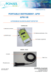
Water under your control
SLUDGE CONCENTRATION
MES-METER APF-MES
REF : PONAPFMES-TRANS
Za du Buisson de la Couldre – 9 allée des châtaigniers
78190 Trappes
TEL : 01 30 16 50 60 – FAX : 01 30 62 43 75
Email : [email protected]– Web : www .ponsel-web.com
Water under your control
User Manual
Including installation and use of MES5 sonde
MES-TRANS meter with MES5 sonde
PONCIR-MES5-S10
Absorbsion Infra red sonde
(5 mm optical sonde)
2
Water under your control
TABLE of CONTENT
ASSEMBLY AND SET UP OF APF-MES-TRANS METER and MES5-S10 SONDE
1. INSTALLATION OF SONDE MES5-S10 ..................................................................................................... 4
2. INSTALLATION OF APF-MES-TRANS METER ....................................................................................... 5
3. Cabling the APF-MES-TRANS and fixing the MES5-S10 sonde to the meter............................................... 5
Drawing I................................................................................................................................................................. 6
3.1. Power supply ........................................................................................................................................... 7
3.2. Cabling of the 4-20mA output.................................................................................................................. 7
4. CONNECTING THE SENSOR TO THE METER......................................................................................... 7
FRONT USER INTERFACE OF APF-MES-TRANS
1.
DESCRIPTION OF THE FRONT USER INTERFACE OF APF-MES-TRANS .......................................... 8
1.1. « M/A » switch (ON/OFF), « MARCHE » (ON) watch led, « FUS » fuse ............................................... 8
1.2. Digital screen .......................................................................................................................................... 8
1.3. Potentiometer «ETAL ». .......................................................................................................................... 8
1.4. Push buttonr « MEM ». ........................................................................................................................... 8
1.5. Potentiometer « Z ». ................................................................................................................................ 9
1.6. Potentiometer « Amt ». ............................................................................................................................ 9
Drawing II .................................................................................................................... Erreur ! Signet non défini.
CALIBRATION OF THE MES-METER WITH ITS SENSOR
1.
3.
Setting the ZERO .......................................................................................................................................... 11
Setting the SLOPE......................................................................................................................................... 11
MAINTENANCE OF THE MES5-S10 SENSOR
1.
Maintenance .................................................................................................................................................. 12
OTHER INFORMATIONS
1.
2.
MAXIMUM PRESSURE LIMIT IN USE .................................................................................................... 13
FIXING THE SENSOR INSIDE PIPES ....................................................................................................... 13
3
Water under your control
ASSEMBLY, SET UP AND INSTALLATION OF APF-MES-TRANS METER and
MES5-S10 SONDE
1.
INSTALLATION OF SONDE MES5-S10.
This sensor is delivered with a standard 10 meter cable (-S10) sealed to the sensor, allowing
up to 5 bar water pressure for 50 meter depths.
For a fixed installation in a basin or in an open canal, we supply PVC perches (50mm tubes)
and fixtures allowing to perform the measures in optimal conditions. You can also get them
directly from your domestic market. Please consult us for more information or before
mounting sensors inside pipes.
Note 1:
This perch is 2,60 meter long, straight or elbowed and can be cut to your size. The sensor is
fixed to the perch through a BP3P-50 connecting joint.
Note 2 :
For optimal results, please follow these suggestions :
•
The sensor must be at least 30 cm under the water surface
•
Avoid dead areas without any water flow.
•
If there is a water flow in one particular direction, it is recommended to position the
optical slot of the sensor in the same direction.
4
Water under your control
2.
INSTALLATION OF THE APF-MES-TRANS METER
See external dimensions in Annexe 4 « TECHNICAL SPECIFICATIONS».
The APF-MES-TRANS box can be fixed indoors or outdoors (protection IP 659 with cover
closed), high enough not to be flooded.
Note :
Avoid putting this equipment in an environment with strong electromagnetic fields.
For instance, do not fix the sensor cable together with high intensity power supply cables, like
pumps : commutations, frequent on and off commands of power elements can be disturbing
despite the excellent shielding of our cables.
In order to allow easy access for calibrations, the APF-MES-TRANS box should be placed at
eyes height and the installation should take in account the need to easily open the transparent
front cover (see appendix ).
The APF-MES-TRANS box has 4 feet to fix it to any vertical surface with 4 screws (∅ 5mm)
which are not supplied.
3.
Cabling the APF-MES-TRANS meter and fixing the SONDE MES5-S10 to the
meter (see drawing 1)
Once the meter firmly fixed on a wall or any vertical surface, proceed like follows:.
1.
2.
Pull away the complete transparent front cover of the meter box after having
unscrewed the 4 screws.
Pull away the lower part which protects the electrical contacts after having unscrewed
the 2 screws: the contacts are now unprotected.
Only 5 out of the available 11 contacts are to be used..
5
Water under your control
Drawing 1
Cabling the APF-MES-TRANS meter and fixing the SONDE MES5-S10 to the meter
6
Water under your control
3.1.
Power supply:
Use a three threads power supply cable (220 V / 50 Hz / 40 VA / 3 x 1,5 mm2) ,
pass it through the watertight right entry on the bottom face of the box, and use
contacts 9 – 10 – 11 on the right side (green-yellow for earth, blue and brown
for 220 V).
Note :
It is essential to check that the 220 V power supply complies with existing
norms, knowing that a lot of disturbances in measuring processes have their
source in an incorrect power supply.
3.2.
Cabling of the 4-20mA output:
The 4-20 mA output has its own power supply and will not deliver more than
24 mA in order not to harm any remote equipment.
1.
Use a telephone pair cable, pass it through the watertight left entry on
the bottom face of the box, and use contacts 1 – 2 on the left side
(contact 1 : – / contact 2 : +)
2.
Screw back the contacts protection and the front cover of the meter.
____________________________________________________________________________
Note :
Maximum allowed load on the 4-20 mA curl is 500 Ω.
Drawing of the contacts in APF-MES-TRANS
7
Water under your control
4.
CONNECTING THE SENSOR TO THE METER.
Simply stick the sensor cable termination into the central plug of the bottom face of the meter
and screw.
The equipment is ready for calibration.
FRONT USER INTERFACE OF APF-MES-TRANS
1.
DESCRIPTION OF THE FRONT FACE OF APF-MES-TRANS (drawing II)
1.1.
« M/A » switch (ON/OFF), « MARCHE » (ON) watch led, « FUS » fuse.
When the “M/A” switch is on “M” the meter is powered, the “MARCHE” led is
permanently lit.
The fuse « FUS » if needed, should be replaced by a 1 A fuse.
1.2.
Digital screen:
The screen is a LCD3 1/2digits (2 000 points). It will count up to 75,00 or 78,00,
suspended matters being measured in g/l as units. Above that value, it will saturate.
1.3.
Potentiometer «ETAL ».
The use of this potentiometer is described in the chapter « CALIBRATION OF THE
MES-METER WITH ITS SENSOR”, setting the SLOPE..
1.4.
Push-button « MEM ».
The use of this button is described in the chapter « CALIBRATION OF THE MESMETER WITH ITS SENSOR”, setting the SLOPE.
8
Water under your control
1.5.
Potentiometer « Z ».
The use of this button is described in the chapter « CALIBRATION OF THE MESMETER WITH ITS SENSOR”, setting the ZERO.
1.6.
Potentiometer « Amt ».
Access to this potentiometer requires taking off the complete cover. It is located on the
right upper part in the box.
This potentiometer allows amortizing the signal when calibrating or measuring.
Turning « AM » clockwise will decrease instability.
9
Water under your control
Drawing 2
Front face of APF-MES-TRANS/REG
10
Water under your control
CALIBRATION OF THE MES-METER WITH ITS SENSOR
1.
Setting the ZERO
1.
First of all, clean the MES5-S10 sensor. The optical glasses of the slot must be cleared
from any dirt or dry sludge.( clean the optical slot with a wet cloth). Then immerse the
sensor in clear water (tape water for instance).
2.
wait eventually during a few minutes for the temperature compensation to be
stabilized, (account for 10 sec./° C temperature spread between sensor and measured
medium, i.e. 5 minutes for ∆ ± 30°C).
2.
Turn potentiometer « Z » until screen displays « 0.00 » (+/- 0.01).
3.
Setting the SLOPE
1.
Setting the slope of the instrument is required before measuring in g/l units suspended
solids concentration in any new medium or sludge. Once this slope is set, no more
slope calibration will be needed for this environment. It requires a laboratory service
able to perform a normalized analysis by filtration or centrifugation
2.
Take a sample of the medium to be measured significant enough in size in order to
allow to immerse completely the sensor (a bucket for instance)
3.
Immerse the sensor in the bucket and gently stir in order to maintain the suspension.
4.
Take a note of :
-
-
5.
The value « a » or its average which is displayed on the screen of the meter.
The value of the slope « x1 »displayed on the same screen when the « MEM »
button on the left of the “Z” potentiometer is pushed and kept in this pushed
position in order to unable a stable reading.
.
Hand over the sample to the Laboratory service which will perform a normalized
analysis by filtration or centrifugation and give back an accurate value of the
suspended solids concentration in g/l .
If necessary, you can ask for several results and take in account only the average
value.
11
Water under your control
6.
If the difference between the result of the Laboratory analysis and the value « a » read
previously on the screen is considered as too important, introduce the slope correction
as follows :
If :
a (mg/l)
X1
b (mg/l)
x2
:
:
:
:
the initial concentration value displayed on the screen.
the initial value of the slope .
the Laboratory value for the medium concentration.
the new value of the slope.
a / x1 = b / x2 → x2 = x1 . (b / a)
Push the « MEM » button and while keeping it pushed, turn the potentiometer
« ETAL » until x2 is displayed on the screen
MAINTENANCE OF THE MES5-S10 SENSOR
Periodically, clean the sensor head with a water spray, insisting particularly on the surfaces
inside the optical slot.
Note :
It is practically impossible to recommend a given frequency for cleaning the sensor, numerous
parameters interfering in the process, among which the quality of the sludge most importantly.
In certain applications, cleaning once a month is enough, in others, it is necessary to clean
every second day.
Progressive and continuous drift in measuring values very often mean the optical surfaces
have been tarnished or covered by a biofilm.
1.
2.
Clean carefully the optical surfaces.
Control and reset if needed the ZERO (see : calibration, setting the ZERO).
12
Water under your control
OTHER INFORMATIONS
1.
MAXIMUM PRESSURE LIMIT IN USE:
The sensor is perfectly water tight, thanks to the excellent sealing between the cable and the
sensor.
Still, we recommend 5 bars as the maximal pressure for permanent use.
For higher pressures, please contact us.
2.
FIXING THE SENSOR INSIDE PIPES:
We have a lot of experience using our sensors in various applications which necessitate
special mountings and fixtures.
Please contact us for:
•
Insertion in pipes with or without pressure;
•
Use in special aggressive mediums;
13
Water under your control
14
Water under your control
ATTACHEMENTS
15
Water under your control
16
Water under your control
17
Water under your control
18