1
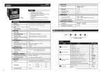
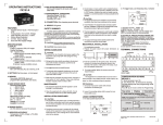
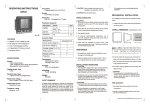
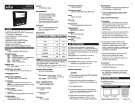
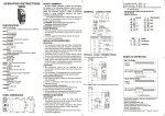
FRONT KEYS DESCRIPTION
FUNCTIONAL SPECIFICATIONS
Programming
Method
Windows based software
for ladder program &
HMI configuration
Memory
Data memory: 16K
Code memory: 128K
No of Objects
Maximum 5000
(as per memory)
Minimum Scan Time
200 µsec
General key description (internal menu)
Display 1
Display 2
Display 3
To Enter into internal menu
(In Internal menu system
settings, digital input
ENT Enter
/output status and
communication settings
can be viewed)
MMI
VER
2.01
SCN
1 (Scan
rate in millisec. with a
least count
of 1ms)
ms
To view system settings,
digital input and output
status when in internal
menu
Press ENT to go to
previous screen.
SET
FUNCTIONAL BLOCKS
FEATURES
= Upto 8 Digital inputs
= Upto 5 Relays / Digital outputs
= One analog input
SPECIFICATIONS
Display
7 segment led
Digits
3 digit + (4 + 4) digit
No. of Keys
5
4
DIGITAL INPUT
No. of Digital Inputs
8
Input Type
PNP
Input Voltage
Range
11 - 28 VDC
(abs. max.: 30 VDC)
Response Time
(Inputs other than
fast counter)
Isolation
For 8DI
IX0,IX1 (2 inputs) - 1 ms
(without debounce)
Others - 10 ms
(with debounce)
Timer
Display Format
Sec, Min, Hr, Day, Min.
Sec, Hr.Min, Day.Hr,
Hr.Min.Sec, Day.Hr.Min.Sec
Counter (8 digits)
Up Counter, Down
Counter, Up / Down
Counter
Isolation
2 kV
Response Time
20 ms
Digital
Digital
Inputs
Outputs
(Status
(Status
DI0 to DI7) DO0 to DO4)
8N2
(Word
Length,
Parity,
Stop Bits)
OFF
OFF
PID Control, Analog input
Key
Communication
Ports
RS485 ports (slave)
SET
User Configurable
(Dual key definition is also possible)
Allows switching between sign (+ve or -ve) for
signed variables
Communication
Protocol
MODBUS/RTU
F1
User configurable
(Dual key definition is also possible)
Moves the cursor to the right by one digit
Memory Retention
10 years
F2
User configurable
(Dual key definition is also possible)
Decrements the digit of the parameter in edit
mode by 1
F3
User configurable
(Dual key definition is also possible)
Increments the digit of the parameter in edit
mode by 1
Not User Configurable
Saves the selected / edited parameter
Supply Voltage
90 - 270 VAC//DC
Temperature
Operating: 0 to 50oC
Storage: -20 to 60oC
Humidity
(non-condensing)
95%
Weight
258 gms
ENT
Edit Mode (Accept data entry task)
User defined HMI Mode
TERMINAL CONNECTIONS
ORDERING INFORMATION
FRONT PANEL DESCRIPTION
LED
Bank A Display 1
LED
Bank B
B
1 2 3 4 5 6 7 8 9 10
Input:- TC / RTD /
0-10V / 0-20 mA
(User selectable)
OFF
Other Blocks
A
ANALOG INPUT
OFF
User defined HMI page
To Exit from internal menu
SET
selec
F1
Display 2
1
2
3
F2
Display 3
4
5
6
-
NO type;
5 A resistive@240 VAC
1
19K2
(Slave ID) (Baud
Rate)
LED Bank A LED Bank B
Key operation in user defined HMI modes
2 kV
No. of Relay Outputs 5
No of Inputs / Type
F1
ENT
DIGITAL OUTPUT- Relay
Relay (NO Type)
Contact rating
To view communication
settings, digital input and
output status when in
internal menu.
Press ENT to go to
previous screen.
TC + /RTD1
ANA IP +
No. of Configurable
Keys
Timer
On Delay, Off Delay,
Operational Modes
Pulse Special (Up / Down)
(Least count .01 sec) Timer(10 ms)
ANA IP TC /RTD2
NTC
SENSOR
MM1010-230V (48X96)
Operating Instructions
RTD3
selec
IP6
IP5
IP4
IP3
IP2
IP1
1
2
3
4
5
6
22
IP7
RS485 +
24
21
IP8
RS485 -
23
7
8
9
10
11 12 13 14 15 16 17 18 19 20
F3
+24V GND NO1 NO2 NO3 NO4 NO5 COM
ENT
MM1010
L(+)
Product
Order Code
MM1010
MM1010-230V
(ordered seperately)
Accessories
Order Code
Communication cable
ACH-001.
Windows-based software
for ladder programming
ACD-003
RS485 to RS232
converter
AC - RS485 - RS232 - 01
N(-)
Document name: Operating/1004/MM1010-230V/ OP-256-VO2
Page 1 of 2
SAFETY PRECAUTIONS
This manual is meant for personnel involved in
wiring, installation, operation and routine
maintenance of the equipment. All safety related
codifications, symbols and instructions that appear
in this operating manual or on the equipment must
be strictly followed to ensure operator and
instrument safety. Any misuse may impair the
protection provided by the equipment.
CAUTION: Read complete instructions prior to
installation and operation of the unit.
ELECTRICAL PRECAUTIONS DURING USE
(CONTD.)
Typical connections for loads :
For load current < 0.5A
MAINTENANCE
1. To avoid blockage of ventilation holes, clean the
equipment regularly using a clean soft cloth.
2. Do not use Isopropyl alcohol or any other organic
solvents for cleaning.
PLC
PLC
C
LOAD
NO
R
L
C
N
Snubber
For bigger loads use interposing relay/contactor
CAUTION: Risk of electric shock.
PLC
INSTALLATION INSTRUCTIONS
CAUTION
1. This equipment, being built-in-type, normally
becomes a part of the main control panel and
the terminals do not remain accessible to the
user after installation.
2. Conductors must not come in contact with the
internal circuitry of the equipment else it may
lead to a safety hazard that may endanger life
or cause electrical shock to the operator.
3. The equipment shall not be installed in
environmental conditions other than those
specified in this manual.
4. Since this equipment forms part of the main
control panel, its output terminals get
connected to the host equipment. Such
equipment shall also comply to EMI/EMC and
safety requirements like BSEN 61326-1 and BS
EN 61010.
5. Thermal dissipation of equipment is met through
ventilation holes provided on chassis of
equipment. Obstruction of these ventilation
holes may lead to a safety hazard.
6. The output terminals shall be loaded strictly as
per the values/range specified by the
manufacturer.
Contactor
PLC
C
NO
R
Snubber
C
LOAD
N
NOTE: Use snubber as shown above to increase life
of internal relay of temperature controller.
B) Use separate shielded wires for inputs.
MECHANICAL INSTALLATION
Outline dimensions (in mm)
Step 1: Make the necessary connection between
MM1010, RS485 to RS232 converter and PC.
Step 2 : Save the ladder to be downloaded in the
PLC and its corresponding HMI and compile
using the Compile option present in Menu Bar
Step 3 : Select the download option from
Communication option from Menu Bar. A
downloader window as shown below appears:
MM1010 is a PLC with built in HMI. The user can
configure the product using SELPRO software.
This software is provided with the product. For
details of the software and configuration method,
please refer to its user manual with the product.
97.5
46
45
To reduce noise:
A) Use of MOV / Snubber circuits across the load
is recommended.
1. Snubber Part no.: APRC-01.
2. MOV Part no.: AP-MOV-03
CAUTION
1. To prevent risk of electric shock, power supply to
the equipment must be kept OFF while wiring.
2. Terminals and electrically charged parts must not
be touched when the power is ON.
3. Wiring shall be done strictly according to the
terminal layout provided in the operating manual.
4. Use lugged terminals to meet M3.5 screws.
5. To eliminate electromagnetic interference use
short wire with adequate ratings and twists of
equal size.
6. The power supply connection cable must have a
cross section of 1sq.mm or greater and insulation
capacity of atleast 1.5KV.
Downloading application programs:
For downloading application program from the PC
to the PLC, follow the steps given below, in
sequence:
FUNCTIONAL DETAILS
Panel cutout
dimensions (in mm)
50
10
WIRING INSTRUCTIONS
MM1010 has one serial RS485 communication
port. Serial communication port is used:
1. To download application program from PC to
PLC.
2. For Online simulation
3. For Standard modbus communication of all the
user defined variables in ladder; PLC acting as
a slave device. The modbus variable table is
generated by the ladder editor and can be
viewed on demand.
SELPRO has two sections:
1. Ladder logic programming section
2. Selec Machine Interface, used for configuration of
HMI
ELECTRICAL PRECAUTIONS DURING USE
Electrical noise generated by switching of
inductive loads can create momentary disruption,
erratic display, latch up, data loss or permanent
damage to the instrument.
C
L
EMC Guidelines:
1. Use proper input power cables with shortest
connections and twisted type.
2. Layout of connecting cables shall be away from
any internal EMI source.
92
88
The display shows pages as configured by the user
in Selec Machine Interface. An internal window is
provided to the user to view status of physical
inputs, physical outputs, system settings and
communication settings. No editing is possible in
this view.
Note: At least one page has to be defined in HMI
2. Remove the clamp from the PLC.
3. Fix the unit into the cutout. Insert the clamp from
both sides and tighten the screws.
CAUTION
The equipment in its installed state must not come
in close proximity to any heating sources, caustic
vapors, oils, steam, or other unwanted process
byproducts.
At power ON the control would go to the first page or
the page sequence defined by user or the page
defined under STR would appear.
Enter password for downloading which is 9303.
Change communication settings as per target
settings.Click on the 'Download' button to start
downloading.
NOTE: Communication settings show default
values. Downloading would take place only if
target comm-unication settings and
communication settings of project match.
(Specifications subject to change as development is a
continuous process).
COMMUNICATION
!
While making communication
connections, make sure that the power
supply to the unit is OFF.
Selec Controls Pvt. Ltd., India,
Tel:91-22-28476443/1882, Fax:91-22-28471733,
Toll free: 1800 227 353, Website: www.selec.com
E- mail: [email protected].
Document name: Operating/1004/MM1010-230V/ OP-256-VO2
Page 2 of 2