1
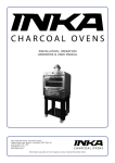
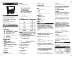
OPERATING INSTRUCTIONS
PIC101-N
8. ISOLATION BREAKDOWN RATINGS:
AC line with respect to all inputs and outputs:
2000 Volts
9. ENVIRONMENTAL CONDITIONS:
Operating Range: 0 to 50oC
Storage Range: -20 to 75oC
Humidity: 85% max.
10. CONNECTION: Wire clamping screw terminal
48 x 96
FEATURES
!
!
!
!
!
Accepts Sensor Inputs : Thermocouple /
RTD
Analog inputs: mV, Current, Voltage.
High Indication Accuracy: ± 0.25%.
Sensor Break Detection.
24 VDC Sensor Supply.
85 to 270 VAC Supply Voltage.
11. WEIGHT: 250 grams
SAFETY SUMMARY
All safety related codifications, symbols and instructions
that appear in this operating manual or on the equipment
must be strictly followed to ensure the safety of the operating
personnel as well as the instrument.
If the equipment is not handled in a manner specified by
the manufacturer it might impair the protection provided by the
equipment.
!
SPECIFICATIONS
1. DISPLAY
4-digit (7 segment LED) 0.5" height
Display Messages:
“Or” - Appears when
1) Measurement exceeds display scaling
range (9999)
2) Open sensor is detected.
“rE” - Appears when
1) Measurement is below display scaling
range (-1999)
2) Sensor reverse condition occurs.
2. POWER SUPPLY
85 to 270 VAC/DC (AC: 50 or 60 Hz), 5 VA
3. SETTINGS Via three keys on front panel.
4. MEMORY
Nonvolatile EEPROM retains all
programmable parameters and values.
5. MAIN SENSOR INPUT
Thermocouple inputs
J : -200 to 750oC
K : -200 to 1350oC
T : -200 to 400oC
R : 0 to 1750oC
S : 0 to 1750oC
RTD input (2 wire or 3 wire)
PT100: -100 to 850oC
mV : 0 - 56 mV
Voltage: 0 to 10 VDC
Current: 0 to 20 mA
6. SENSOR SUPPLY
24 VDC (30mA) to power the sensors
7. INDICATION ACCURACY
Temperature: 0.25% of Span ±1oC (After
20min. Warmup)
CAUTION: Read complete instructions prior to
Installation and operation of the unit.
CAUTION: Risk of electric shock.
WIRING GUIDELINES
CAUTION:
1. To prevent the risk of electric shock power supply to the
equipment must be kept OFF while doing the wiring
arrangement.
2. Wiring shall be done strictly according to the terminal
layout with shortest connections. Confirm that all
connections are correct.
3. Use lugged terminals to meet M3 screws.
4. To eliminate electromagnetic interference use of short
wire with adequate ratings and twists of the same in
equal size shall be made.
5. Cable used for connection to power source, must have a
cross section of 1mm2 or greater. These wires shall have
insulation capacity made of at least 1.5KV.
3. Circuit breaker or mains switch must be installed between
power source and supply terminals to facilitate power 'ON'
or 'OFF' function. However this switch or breaker must be
installed in a convenient position normally accessible to the
operator.
2. Fuse Protection: The equipment does not have a built-intype fuse. Installation of external fuse ofrating75VAC/1Amp
for electrical circuitry is highly recommended.
3. Thermal dissipation of equipment is met through ventilation
holes provided on chassis of equipment. Such ventilation
holes shall not be obstructed else it can lead to a safety
hazard.
4. The output terminals shall be strictly loaded to the
manufacturer specified values/range.
MECHANICAL INSTALLATION:
For installing the controller
1. Prepare the panel cutout with proper dimensions as
shown (in mm)
C
Contactor
NO
R
MOV
C
Snubber
C
LOAD
1) Snubber Part No.: APRC - 01.
2) MOV Part No.: AP-MOV - 03.
Note: For inductive loads, use of snubber and
MOV, as shown above, is recommended.
ELECTRICAL PRECAUTIONS DURING USE
Electrical noise generated by switching of inductive
loads can create momentary disruption, erratic display,
latch up, data loss or permanent damage to the instrument. To reduce noise:
a) Use of MOV across supply of temperature
controller & snubber circuits across loads are
Recommended
b) Use s eparate shielded wires for inputs.
TERMINAL CONNECTIONS
mV/TC/RTD
45 46
50
-
+
Panel Cutout
B
A
97.5
10
92
88
2. Push the controller into the panel cutout. Secure the
controller in its place by pushing the clamp on the
rear side. The screws, of the pane of the clamp, must
be in the farthest forward slot.
3. For proper sealing, tighten the screws evenly with
required torque.
1
2
3
B’
4
V
mA
+ -
+ -
5
6
7
8
CONFIG
9
10
22
24
21
23
11 12 13 14 15 16 17 18 N
L
+24V GND
-
sensor supply
+
! CAUTION:
The equipment in its installed state must not come in
close proximity to any heating sources, caustic vapors, oils,
steam, or other unwanted process by-products.
EMC Guidelines:
1. Use proper input power cables with shortest
connections and twisted type.
2. Clean the equipment with a clean soft cloth . Do not
use isopropyl alcohol or any other cleaning agent.
2. Layout of connecting cables shall be away from any
internal EMI source.
INSTALLATION GUIDELINES
LOAD CONNECTIONS
! CAUTION:
1. This equipment, being built-in-type, normally becomes a
part of main control panel and in such case the terminals
do not remain accessible to the end user after installation
and internal wiring.
1. For load current less than 0.5A
2. Conductors must not come in contact with the internal
circuitry of the equipment or else it may lead to a safety
hazard that may in turn endanger life or cause electrical
shock to the operator.
TC
TC
! CAUTION:
1. The equipment shall not be installed in environmental
conditions other than those mentioned in this manual.
1. The equipment should be cleaned regularly to avoid
blockage of ventilating parts.
MAINTENANCE
2. For bigger loads, use interposing relay / contactor
CONFIGURATION SCHEME
METHOD 1:
1. Short terminals 9 and 10.
2. Turn Power ON. 3. Remove the shorting.
Unit will directly enter into programming mode.
METHOD 2:
Press
+
for 3 sec to enter into Programming
Key press
Display
Description
1. Lock code for program entry
Factory setting:
NOTE: This parameter will not be prompted if programming is
entered using METHOD 1.
N
L
(Display
for 1 second)
TC
TC
C
NO
LOAD
R
C
Press
as
+
key and program the lock code
MOV
Snubber
Document name: Operating / 0807/ PIC101-N /
Page 1 of 2
OP162-V03
Key press
2. Press
Display
Description
to program Sensor type
for 1 second)
(Display
J : -200 to 750 C
Press
+
K : -200 to 1350oC
Press
+
T : -200 to 400oC
o
R : 0 to 1750 C
+
S : 0 to 1750 C
PT100
(-100 to 850OC)
+
Press
+
Press
+
Press
+
Current
Press
+
Voltage
3. Press
Range:DSCL to 9999
( display as per decimal
point selected.)
NOTE: Valid for analog inputs (mV, current, voltage)
(Display
mV : 0 to 56 mV
Press +
/
to change value.
for 1 second)
Range : ISCL to
9. Press
To scale the controller, two scaling points are necessary.
Each scaling point has a coordinate pair of Display Values
and Input Values. It is recommended that the two scaling
points be at the low and high ends of the input signal being
measured. Process value scaling will be linear between and
continue past the entered points to the limits of the input
range. (Factory settings example will display 0.0 at 0 mA
input and display 9999 at 20.00 mA input.) Reverse acting
indication can be accomplished by setting
DISPLAY
9999
0.0
key to select Reverse scaling
Factory setting:
0.00mA
ISC.L = 0.00
DSC.L = 0.0
RSCL = no
for 1 second)
O
(Display
TC/RTD: 1 / 0.1 C
Press
Analog input: 1/
0.1/0.01/0.001
(Decimal point
position)
+
Press
+
Press
+
4. Press
Factory setting:
for 1 second)
Press
NOTE: Valid for analog inputs (mV, current, voltage)
(Display
Press + /
to change value.
for 1 second)
-
Factory setting:
+
mA
(Display
Press +
/
to change value.
for 1 second)
(Display
(Display
Press +
/
to change value.
Range: 0.0mA/V/mV
to ISCH
K
2
3
4
5
7
6
8
9
10
22
24
21
23
11 12 13 14 15 16 17 18 N
+24V GND
Press +
/
to change value.
Range : -99.9 to
+ 99.9 OC
+
+
12. Press
Factory setting:
Press
+
External
24 VDC
Supply
-
A
1
B
2
3
B’
4
V
mA
+ -
+ -
5
6
7
8
CONFIG
9
key to reset all the parameters
10
22
24
21
23
11 12 13 14 15 16 17 18 N
Press
DISPLAY
VALUE
0.0
0.0
10.0
10.0
0.0
0.0
20.0
20.0
CHECKED BY:
mV/TC/RTD
+
for 1 second)
CALIBRATION
VALUE
( 0.1Resolution)
-
key to select reset all
(Display
-
Two-wire
Transmitter
DISPLAY
VALUE
(oc)
35.0
700.0
1350
0.0
500.0
800.0
Unit is accepted as accuracy is within the
specified limit of claimed accuracy and certificate
is valid up to one year from the date of issue
+
(Fixed 0.1 resl for TC/RTD
& 1 unit for analog input)
CALIBRATION
TEMP.(OC)
( 0.1Resolution)
35.0
700.0
1350
0.0
500.0
800.0
The thermocouple / RTD curves are linearised in
this microprocessor based product; and hence the
values interpolated between the readings shown
above are also equally accurate; at every point in
the curve.
L
-
Voltage
(VDC)
Current
(mA)
for 1 second)
for 1 second)
(default value changes
as per analog input selected)
CONFIG
Connection with external 24VDC supply :
6. Press
key to program Input
Factory setting:
scaling point low
NOTE: Valid for analog inputs (mV, current, voltage)
Two-wire
Transmitter
+ -
1
Range : OFF, 1 to
99 sec.
key to program PV Bias
Range: -1999 to DSCH
( display as per decimal
point selected.)
SENSOR
SENSOR
key to program Filter time
Factory setting:
Factory setting:
The calibration of this unit has been verified at the
following values:
Connection with Internal 24VDC Sensor supply :
+
key to program Display
Multimeter calibration report no:
ERTL (W), Mumbai, INDIA
PT100
Eg. : for 4-20 mA input
+
11. Press
scaling point low
Sources calibrated against:
Hinditron Multimeter, Model 86, Sr.No.:1094
for 1 second)
key to select Temperature unit.
(Display
5. Press
ISC.H = 20.00
DSC.H = 9999
reverse scaling parameter
as YES. In this case
referring the above eg.
for 0.00 mA input the
display will show 9999 and
20.00 mA input the display
will show 0.0.
NOTE : This change will
not be visible in the
programming menu.
Claimed Accuracy: ± 0.25 % of full scale ± 1
digit (After 20min warmup time)
Connection with 2-wire Transmitter
10. Press
constant
NOTE: Valid for TC / RTD inputs
Press
INPUT
20.00mA
Factory setting:
NOTE: Valid for analog inputs (mV, current, voltage)
(Display
Model No:
Sr. No.:
USER GUIDE
20.00mA/10.00V/56mV
(default value changes as per
analog input selected)
to program Resolution.
Date:
Unit will auto exit the programming
mode if no key is pressed for 60 sec
SCALING FOR ANALOG INPUT:
8. Press
key to program Input
scaling point high
Factory setting:
o
Press
Press +
/
to change value.
for 1 second)
CALIBRATION CERTIFICATE
Program Exit:
Press
+ key for 3 sec
Description
NOTE: Valid for analog inputs (mV, current, voltage)
o
Press
Display
7. Press
key to program Display
Factory setting:
scaling point high
Factory setting:
(Display
Key press
+24V
Sensor
GND
supply
-
(Specifications subject to change as development
is a continuous process).
Selec Controls Pvt. Ltd., India.
(Formerly Selectron Process Controls Pvt. Ltd.)
L
Tel:91-22-28476443/1882, Fax:91-22-28471733,
Toll free: 1800 227 353, Website: www.selecindia.com
E- mail: [email protected].
+
Document name: Operating / 0807/ PIC101-N /
Page 2 of 2
OP162-V03