1
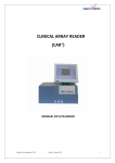
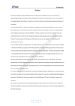
Clinical Array Reader (CAR)
User Manual
CLINICAL
ARRAY READER
(CAR)
USER MANUAL
Clinical Array reader (CAR) Manual
Version 4
July 2009
1
Clinical Array Reader (CAR)
User Manual
1. TABLE OF CONTENTS
1. Table of contents
1
2. Introduction
4
3. Components Description and Specifications
5
4. Installation
7
4.1 Precautions
4.2 Unlock/lLock
4.3 Assembling Screen
4.4 Connecting screen and reader
5. Safety Notes
11
6. Procedural Limitations
11
7. Switching on/off
12
8. Performing Strips (ASs)
8.1 Setting Samples Number
14
8.2 Setting Assay IDs
17
8.3 Setting Sample IDs
18
8.4 Working List
20
8.5 Reading
20
8.6 Summary Report and Results
22
8.7 Sample Reanalysis
25
9 Performing ATs
10.
9.1 Placing ATs on the Adaptor
28
9.2 Changing Rack Type
29
9.3 Setting Samples Number
30
9.4 Setting Assay IDs
31
9.5 Setting Sample IDs
32
9.6 Working List
34
9.7 Reading Process
34
9.8 Summary Report and Results
36
9.9 Sample Reanalysis
38
Main Menu Options
10.1 Archive
42
10.2 Service
43
10.2.1 Import
44
10.2.2 System
44
Clinical Array reader (CAR) Manual
Version 4
July 2009
2
Clinical Array Reader (CAR)
User Manual
10.2.3 Backup/Backup Path
45
10.2.4 Settings
49
11. FAQ
11.1 Updating software
50
11.2 Exporting results – Backup path
53
11.3 Barcode Reader: Characteristics and Installation
56
11.4 Dongle. What it is and its use
56
Appendix 1- Abbreviations Used
57
Appendix 2 - Symbols and Warning Signs
57
Clinical Array reader (CAR) Manual
Version 4
July 2009
3
Clinical Array Reader (CAR)
User Manual
2. INTRODUCTION
The Clinical Array Reader (CAR) has been designed for a quick detection and analysis of
ASs. This detection and analysis represent the second step of an ASs assay. The first
step of a complete ASs assay also involves experimental procedures (sample preparation,
DNA extraction, DNA amplification and target labelling, specific hybridisation and
visualization of the results).
Visualization
Experimental Procedures
The detection and analysis of ASs by the CAR is always performed immediately after
developing the specific precipitation staining pattern on the ASs chip. Developing of this
pattern generates a dot micromatrix (microarray) on the glass slide at the bottom of the
ASs. This micromatrix can be detected and analysed by the CAR. The results obtained by
the CAR are automatically shown on the touch screen and can be printed or exported to
your LIMS or pen-drive by its USB connection.
Sample preparation, DNA extraction and
DNA amplification/labelling of targeted
molecules
Standard
laboratory
equipment
Specific hybridisation: labelled sample
incubation against AS-chip.
Visualization: conjugation and precipitation
of the staining.
Colorimetric Detection and Analysis.
CAR
(Clinical Array
Reader)
Clinical Array reader (CAR) Manual
Version 4
July 2009
4
Clinical Array Reader (CAR)
User Manual
3. COMPONENTS DESCRIPTION
Touch screen
Reader’s tray
Function’s gauge
Performance:
Resolution on the sample: 3 µm
Camera pixel resolution: 8.3 Mpixel
Scan time for complete 96-well plate: 2-3 minutes
Dynamic Range: 8-bits, 255 greyscale
Mechanical:
Dimensions
Width
Height
Depth
44 cm
21 cm
34 cm
Additional 10 cm space must be provided in front of the instrument for microplate loading,
as well as an additional 10 cm space at the back for cables and ventilation.
Weight (without tactile screen) 15 Kg
Replacement fan filter 80x80mm NMB, Part No.: F80/MR
Environmental:
Environmental Conditions
Operating Temperature
Storage Temperature
Relative Humidity (noncondensing)
0 – 70 ºC
-40 a + 85 ºC
10 – 75 %
Clinical Array reader (CAR) Manual
Version 4
July 2009
5
Clinical Array Reader (CAR)
User Manual
Electrical:
Electrical Specifications
Rated Power
Fuse type and rating two
fuses
Voltage
150 W
5x20 mm, 250V 1.6A slowblow
110 – 230 V (AC) a 50/60
Hz
Image storage format 8-bit BMP greyscale
Results storage format CSV spreadsheet
Internal PC:
Specifications
Operating System
Processor
RAM Memory
Hard Disk
Connections
Windows XP home edition
Intel Pentium II 1.6 GHz ( o mayor)
1 GByte DDR-2
40 GByte
VGA, RS-232 (mouse and keyboard),
Serial100 Base-T Ethernet, 3x USB2
Touch screen:
Characteristics
Type
Resolution
Colours
Connections
12.1” TFT LCD
800x600
264 K
12V, VGA, USB-B,
Mechanical mount VESA 75
Max current for 12VDC tactile screen supply: 3 Amp.
Clinical Array reader (CAR) Manual
Version 4
July 2009
6
Clinical Array Reader (CAR)
User Manual
4. INSTALATION
Please, follow the indications described in this manual to set up the Clinical
Array Reader (CAR).
4.1 PRECAUTIONS
- Verify that the instrument does not present any obvious sign of damage. If any
damage is found, please contact immediately to your local GENOMICA’s
representative.
- Prepare approximately 1 m3 free area in the lab for the installation of the CAR.
Once unpacked, place your CAR in a standing position on the bench space you
have just prepared. Relocation of your CAR is only recommended by lifting it,
DO NEVER PUSH YOUR CAR.
- Make sure that the CAR is placed on a stable and perfectly horizontal bench.
- Before connecting it to the power supply, make sure that your power line voltage
corresponds to the operating voltage of 110-230 V (AC) at 50/60 Hz.
- Do not install the CAR in the influence area of a heat or intense light source.
4.2 UNLOCK/LOCK THE READER
In order to avoid system damages during transport, internal mobile components
of the CAR are locked. In order to unlock the reader, remove the big screw on
the back and side.
Readers contain two locking systems, one on the rear side and one in the right side.
During transportations, the position of the tray holder is fixed by lock screws, in order to
protect the mechanical components. Remove these screws before switching on the
instrument for the first time and keep them for the posterior assembling of the screen.
No special tools are required to remove both screws.
Clinical Array reader (CAR) Manual
Version 4
July 2009
7
Clinical Array Reader (CAR)
User Manual
Fig.1: Unlocking the CAR. Position of the locking screws.
Place the white plastic cap attached in the hole left by the lock screw at the side of the
CAR (Fig. 2)
Fig. 2: Covering the side hole left by the screw..
Should you need to send or ship your instrument, the lock screws must be screwed
securely in their positions.
To install the transport lock screws, please follow these short instructions:
- Turn off the instrument and remove the main power connection.
- Slowly slide the tray holder manually fully towards the rear wall and place the
screw at the rear of the CAR.
- Then slide the tray holder fully to the right and place the screw on the side.
- Tight them securely.
Clinical Array reader (CAR) Manual
Version 4
July 2009
8
Clinical Array Reader (CAR)
User Manual
4.3 ASSEMBLING THE SCREEN
Touch screen is provided separately. In order to connect it, please follow these
indications:
1. Unscrew partially the two lower screws (yellow), and totally those marked in red,
all of them are placed on the rear side of the reader.
2. Lean the screen over the reader fitting the screws with the positions marked in
yellow. Insert the safety lock screws recently removed (green circles, below) in the
positions marked in red (See below).
3. Once installed, screen’s arm should appears as follow:
Clinical Array reader (CAR) Manual
Version 4
July 2009
9
Clinical Array Reader (CAR)
User Manual
4.4 CONNECTING SCREEN AND READER
2
1a, 1b, 1c
Clinical Array reader (CAR) Manual
Version 4
July 2009 10
Clinical Array Reader (CAR)
User Manual
1. Connecting cables:
1a) Connect the power supply (Type Jack 3.5)
1b) Connect the USB connection to one of those at the right side.
1c) Connect the VGA connection to the blue connector.
2. Switch on the screen by pressing the button on top.
5. SAFETY NOTES
Please, be particularly aware of electrical hazards. Standard electrical safety
precautions must be applied at all times. Only qualified personnel are permitted to
perform electrical servicing.
- Never touch switchers or outlets with wet hands.
- Always switch off the instrument before disconnecting the AC power cord.
- Always unplug the instrument prior to cleaning major liquid spills and prior to
servicing the electrical or internal components.
- Do not open the instrument case.
- Avoid any movement or vibration during reading operation.
6. PROCEDURAL LIMITATIONS
-
Clinical Array Reader (CAR) was designed for the detection and analysis of ASs
(Array Strips) or ATs (Array Tubes) only. Any other tubes, vials, or material must not
be used with this equipment.
-
Only use Array Strips or Array Tubes processed in accordance to the AS/AT
experiment protocols provided by GENOMICA.
-
Use of this equipment in a different way of that described in this manual will result in
lost of your warranty rights
Please take care that the USB used for software updates or results export does
not contain any virus. GENOMICA is not responsible about virus infections and
CAR cleaning will not be considered as a part of the technical support.
Clinical Array reader (CAR) Manual
Version 4
July 2009 11
Clinical Array Reader (CAR)
User Manual
7. SWITCHING ON/OFF THE CAR
7.1 SWITCHING ON
Connect the Dongle to a free USB port (see FAQ 11.4).
Plug in the reader and switch it on. The main switcher is on the rear (right) side of the
device. Once pressed, function gauge will display a yellow light.
Press then the secondary switcher, on the front side of the CAR and wait until function’s
gauge turns green.
Once your CAR is switched on the instrument will initialise, during this time the instrument
will verify its good performance by a series of self tests.
After finishing this set of self tests the “Main Menu” screen will appear on the touch screen
which will allow to start reading and analyzing the samples.
Fig.: Secondary switcher at the front side
7.2 SWITCHING OFF
Press first “Shut Down” box on the main menu to switch off the CAR and then turn off the
main switcher at the back side.
It is important to shut down the CAR when not required, as this may lengthen its half-life
(Fig. 1).
Clinical Array reader (CAR) Manual
Version 4
July 2009 12
Clinical Array Reader (CAR)
User Manual
Fig. 1: Shut down option at the GENOMICA’S main menu
Do not switch off the reader directly since it could damage it.
Clinical Array reader (CAR) Manual
Version 4
July 2009 13
Clinical Array Reader (CAR)
User Manual
8. 8. PERFORMING STRIPS (ASs)
Reading and analyzing samples is a sequential easy procedure, compose by multiple
menus where user can choose among the several options of the application.
For starting a new analysis, choose option “New Analysis” on the application’s main menu
(Fig. 2).
Fig.2: Main menu of the GENOMICA’s application
Once this option is selected, a new menu will pop up on the screen, where 96 wells
microplate sketch is depicted (Fig. 3).
Fig. 3: 96 wells microplate sketch on the “New Analysis” menu.
This menu (Fig. 3) represents the cornerstone of the application, since it allows the user
to:
-
Set rack type: choose between 96 wells microtitter plate (AS) or tubes adaptor (AT).
Clinical Array reader (CAR) Manual
Version 4
July 2009 14
Clinical Array Reader (CAR)
-
User Manual
Set the sample’s number to be processed.
Set assay ID (HPV, Pneumovir, Entherpex...).
Set sample ID (Sample Reference).
8.1 SETTING SAMPLE’S NUMBER
The number of samples to be analysed can be introduced manually or automatically,
using a barcode reader.
It’s not necessary to place the ASs in correlative positions for their lecture.
Nevertheless, when the CAR is included in a Clinical Array Processor (CAP),
ASs must be placed in correlative order, at the left side of the frame.
Automatic setting:
For the automatic setting of sample’s number, user will need a bar-code reader connected
to the CAR (normal USB connection)(See FAQ). GENOMICA will provide the user with
specific bar codes for each assay.
Press “Set Assay IDs” option, placed on the lower left side of the screen and all ASs will
turn unselected on the “New Analysis” menu (Fig. 4).
Fig.4: Left: Set Assay ID option on the lower left side of the screen. Right: All strips turn unselected when chosen this option
When reading a barcode, an AS is activated, automatically, on the microplate sketch and
colour combination turns from grey into a specific assay’s colour combination. (Fig.5)
Clinical Array reader (CAR) Manual
Version 4
July 2009 15
Clinical Array Reader (CAR)
User Manual
Fig. 5: Specific colours combinations. Red: HPV, Blue: Pneumovir, Green: Entherpex.
Manual setting:
Software’s default settings, establish the analysis of the whole microplate, composed by
up to 12 ASs. All ASs not included in the process, must be manually unselected by the
user.
symbol, which will turn into
, indicating
To unselect them, proceed to press on the
the “no selection” of the AS. The unselected AS appears on a light-grey colour (Fig. 6).
Fig. 6: Selection of AS number.
Sample’s number should be, always, a whole multiple of eight, which is the
number of wells included in each AS.
Clinical Array reader (CAR) Manual
Version 4
July 2009 16
Clinical Array Reader (CAR)
User Manual
8.2 SETTING ASSAYS IDs
The automatic setting of sample’s number, in the previous section, allows the user
to skip this step.
Setting Assays IDs Manually:
Software processes by default the CLART® HPV2 assay. To read or analyse any other
GENOMICA’S CLART® Kit, press the
button on the “New Analysis” menu (Fig. 7a),
placed under each column.
Option “Edit” activates a new window (Fig. 7b) that lets the user choose among those
shown in the pull-down menu.
User can apply same Assay ID to the whole plate from the Edit menu.
Fig.7a: Selecting “Edit” option on the”New Analysis” menu.
Fig. 7b: Manual setting of Assays IDs. A pull down menu shows the multiple choices to choose among
Clinical Array reader (CAR) Manual
Version 4
July 2009 17
Clinical Array Reader (CAR)
User Manual
Press “OK” when finish, to return to previous menu and follow up with the visualization
process.
Once assigned the assays’ IDs, strips will turn to the different colour combination specific
for each type of analysis (Fig. 7C)
Fig.7c: Diferent colours combinations corresponding to different assays.
8.3 SETTING SAMPLES IDs
In the same way that in previous sections, setting Samples IDs can be carried out,
automatically or manually.
In case of no Samples IDs assigment, software will set automatically a
correlative number to each sample, from 1 to 96, starting with the sample placed
in position 1A (upper-left).
Setting Samples IDs Automatically
Barcode reader is required to set Samples IDs automatically and barcodes must
be set and printed before start setting the IDs.
Set and print barcodes before starting.
Clinical Array reader (CAR) Manual
Version 4
July 2009 18
Clinical Array Reader (CAR)
User Manual
Press “Set Samples IDs” option and read the previously assigned barcodes normally. The
software associates automatically a barcode to a sample position. Samples with already
assigned ID will appear in black (Fig. 8)
Fig 8: Setting Samples ID automatically.
Once finished importing IDs, press “Stop Import” to return to the “New Analysis” menu.
Setting Samples IDs Manually
Select each position individually by pressing twice on it. A new window representing a
“tactile key board” will pop up on the screen (Fig. 9). Use it to set samples ID manually.
Fig 9: Setting “Samples IDs” manually, using the tactile keyboard.
Clinical Array reader (CAR) Manual
Version 4
July 2009 19
Clinical Array Reader (CAR)
User Manual
The user can check the sample position at any time, since it appears at the upper-left side
of the screen.
Once finished with samples’ identification process, press “OK” to go back to the “New
Analysis” menu (Fig.2).
Then press “NEXT”.
8.4 WORKING LIST
The working list allows the user to check, whether the already introduced information
(samples references, assays...) is correct or not.
To change any data, just press “Back” and repeat the setting process again (see “Set
Samples IDs Manually” and “Set Assays ID Manually").
If all information is correct, press “Start” to carry on with the reading process (Fig. 10).
Fig. 10: Working list, prior to analyzing. The working list includes necessary information for the samples’ traceability
(references, assay ID, position on the microplate...).
8.5 READING PROCESS/ TAKING IMAGES
Reader’s tray opening and closing processes are automatic. Do not try to force
or move it manually. If neccessary, press the emergency button placed on the
rear side of the CAR.
User will be requested to initialize the process (Fig. 11), by pressing the “Open Tray” box.
Clinical Array reader (CAR) Manual
Version 4
July 2009 20
Clinical Array Reader (CAR)
User Manual
Fig.11: Message to initialize the reading process.
Once finished the opening process, place the microplate (ASs) manually in the tray and
operate the “Close Tray” box. (Fig.12).
Fig. 12: Message to activate the closing process of reader’s tray.
Reading procedure can be monitored in the screen since samples/wells change their
colour indicating the reading status (Fig.13):
-
Wells in green: Sample already analysed. Grid alignment
agreed.
-
Wells in red: Sample may be reanalyzed. Grid alignment failed
(see “Sample Reanalyze” section below).
-
Wells in yellow: Sample has not been analyzed yet.
Clinical Array reader (CAR) Manual
Version 4
July 2009 21
Clinical Array Reader (CAR)
User Manual
Fig.13: Monitoring the reading process in the CAR’s screen. Different colours for different analysis status.
Once finished the reading process, user will be requested again to initialize the opening
and closing procedures. (Figs. 12 and 13).
Results will be shown once the microplate has been removed from reader’s and tray is
closed.
8.6 SUMMARY REPORT AND RESULTS
SUMMARY REPORT
The CAR generates a final report including following information:
-
Date and time
Position of the sample
Assay ID
Sample ID
Results for each sample
User can look up the final report by selecting “Report View” option. It’s possible to print out
this run report in PDF format, just by pressing the print option on the upper right side of
the screen (Fig. 14).
Clinical Array reader (CAR) Manual
Version 4
July 2009 22
Clinical Array Reader (CAR)
User Manual
Fig. 14: Summary report created by the CAR at the end of the analyzing process..
RESULTS
To visualize a specific sample’s result, select the sample/position on the microplate sketch
(Fig.15) by pressing twice on it. A new menu, showing working list and results, will appear
on the screen (Fig. 16). On this menu, following options are shown:
Export: To export reports and results to an external server, LIMS or USB.
Print: If an external printer is connected via USB port, the selected result’s page or
all results data pages, including test image, can be printed by operating the "Print"
button (See FAQ)
Image: To visualize the image obtained by the CAR (Fig.18).
Raw Data: To consult raw and normalized numerical values obtained in the analysis
of the samples.
Clinical Array reader (CAR) Manual
Version 4
July 2009 23
Clinical Array Reader (CAR)
User Manual
Fig.16: Results menu
By selecting the “Image” option, user accesses to the image corresponding to the
analyzed sample (Fig. 17 and 18)
Fig.17: Selecting “Image” option
Clinical Array reader (CAR) Manual
Fig. 18: Example of a HPV assay performed in strips (metal
markers).
Version 4
July 2009 24
Clinical Array Reader (CAR)
User Manual
By selecting “Raw Data” option, user accesses to the numerical values measured
for each virus type (Fig. 19 and 20).
Fig. 19: Selecting “Raw Data” option
Fig.20: Raw data and normalized values
8.7 REANALYZING SAMPLES
After the analysis process, red coloured wells, where the grid alignment has failed, can be
reanalyze manually by user.
In the microplate sketch menu (Fig.15), press on a red coloured sample/position to
activate the reanalysis main menu window.
Browse the proper Assay among those from the pull down menu (Fig.21) and press “Start
Reanalyze”.
Fig.21: Main menu of the reanalyze option for ASs.
By operating “Start Reanalyze” button, user accedes to the reanalysis application.
Clinical Array reader (CAR) Manual
Version 4
July 2009 25
Clinical Array Reader (CAR)
User Manual
The correct grid alignment consist in positioning the upper left marker over the upper left
metal marker and then, adjusting the whole grid size by using the lower right metal
marker. Once the grid is squared properly, according to array’s dot micromatrix, press
“Reanalyze” button (Fig. 22).
Fig. 22: Placing metal markers according array’s matrix.
Zoom tool, placed on the upper right corner of the screen, facilitates the reanalysis
process:
Fig. 23: Manual grid alignment in strips, using metal markers, and zoom tool.
Once the metal markers are aligned, press “Reanalyse” option (Fig 23) and an image with
the grid will show the final alignment. If both, dots and metal markers fits press “Accept”
(lower- right side). If new adjustments are required, press “Retry” (Fig. 24)
Clinical Array reader (CAR) Manual
Version 4
July 2009 26
Clinical Array Reader (CAR)
User Manual
Fig. 24: Grid alignment checking
Manual grid alignment implies user’s intervention in the results. If a manual grid
alignment is required, an informative message will be shown in the run report.
The image has been reanalyzed.
Fig.25: Informative message indicating the manual reanalysis.
Clinical Array reader (CAR) Manual
Version 4
July 2009 27
Clinical Array Reader (CAR)
User Manual
9. PERFORMING ARRAY TUBES
9.1 PLACING ARRAY TUBES ON THE TUBE ADAPTOR
The ATs adaptor is provided by GENOMICA and allows the user to place up to 12 ATs for
analyzing.
For the adequate analysis of the tubes, is necessary to place them properly on the
adaptor.
Open the AT tube completely and turn back its cap. Hold the tube in this position and
introduce both, tube and cap, at the same time into the adaptor as shown in Fig. 26.
Tubes will be read in columns, like the ASs, starting from position A1, which is placed on
the blunted square of the tube adaptor (upper left position).
Fig. 26: Placing tubes in the adaptor.
Select “New Analysis” option at the main menu of Genomica’s application (Fig. 27).
Fig. 27: Selecting “New Analysis” at the main menu of Genomica’s application.
Clinical Array reader (CAR) Manual
Version 4
July 2009 28
Clinical Array Reader (CAR)
User Manual
9.2 CHANGING RACK TYPE
The software establishes the analysis of a whole 96 plate as default, composed by up to
12 ASs.
In case of analyzing ATs, user should change the rack type.
To change the rack type, just select the pull down menu “Select Rack” on the top of the
screen and choose “Tube adaptor” (Fig. 28) instead of “96 well plate”.
Fig. 28: “Select rack” option at the upper left side of screen.
A new window will pop up showing the tube adaptor sketch (Fig. 29).
Fig 29: Main menu when reading ATs.
Clinical Array reader (CAR) Manual
Version 4
July 2009 29
Clinical Array Reader (CAR)
User Manual
9.3 SETTING SAMPLE’S NUMBER
The number of samples to be analysed can be introduced manually or automatically, by
using a barcode reader.
Automatic setting:
For the automatic setting of sample’s number, user will need a bar-code reader connected
to the CAR (normal USB or PS/2 connection).
Once the adaptor type is changed (see “Changing Rack Type” above) press “Set Assay
IDs” option on the lower left side of the screen and all positions will turn unselected (Fig
30 and 31). Read as many barcodes as sample’s number you have and tubes will turn to
the specific assay’s colour combination (Fig. 32).
Fig. 30 and 31: Setting Assay IDs automatically
.
Fig. 32: Different colours combinations for each array type
Clinical Array reader (CAR) Manual
Version 4
July 2009 30
Clinical Array Reader (CAR)
User Manual
Manual setting:
In case of analyzing ATs, those tubes that are not going to be processed, should be
unselected manually by pressing on
indicated with
(Fig. 33).
symbol. The no selection of one tube will be
symbol and the tube position will turn into a light/dark grey combination
Fig.33: Selected positions appearing in assay’s specific combination. Unselected positions turned into light/dark grey
combination.
9.4 SETTING ASSAYS IDs
The automatic setting of sample’s number, in the previous section, allows the user to skip
this step, because assays ID’s are already set.
Setting Assays IDs Manually:
Software processes by default the CLART® HPV2 tubes. To read or analyse any other
GENOMICA’S CLART® KIT, select the position (by pressing on it) and then press “Edit
Assay” option.
Select the proper assay from those appearing in the pull-down menu as shown (Fig. 34)
Clinical Array reader (CAR) Manual
Version 4
July 2009 31
Clinical Array Reader (CAR)
User Manual
Fig.34: Multiple assays choices.
Software gives also the possibility to select all tubes and edit the assay ID in all of them at
same time. In case of processing all samples with same assay, user should select the
“Assign Assay to all samples” on the Edit menu (Fig. 34).
9.5 SETTING SAMPLES IDs
In the same way that in previous sections, setting Samples IDs can be carried out,
automatically or manually.
In case of no Samples IDs assigment, software will set automatically a
correlative number to each sample, from 1 to 12, starting with the sample placed
in position 1A (upper-left).
Setting Samples IDs Automatically
Barcode reader is required to set Samples IDs automatically and barcodes must
be set and printed before start setting the IDs.
Set and print barcodes.
Press “Set Samples IDs” option and read the previously assigned barcodes normally. The
software associates automatically a barcode to a sample position. Samples with already
assigned ID will appear in black (Fig. 35)
Clinical Array reader (CAR) Manual
Version 4
July 2009 32
Clinical Array Reader (CAR)
User Manual
Fig. 35: Setting Samples ID automatically.
Once finished importing IDs, press “Stop Import” to return to the “New Analysis” menu.
Setting Samples IDs Manually
Select each position individually by pressing twice on it. A new window representing a
“tactile key board” will pop up on the screen (Fig. 36). Use it to set samples ID manually.
Fig 36: Setting “Samples IDs” manually, using the tactile keyboard.
The user can check the sample position at any time, since it appears at the upper-left side
of the screen.
Once finished with the samples’ identification process, press “OK” to go back to the “New
Analysis” menu (Fig.29).
Then press “NEXT”.
Clinical Array reader (CAR) Manual
Version 4
July 2009 33
Clinical Array Reader (CAR)
User Manual
9.6 WORKING LIST
The working list allows the user to check, whether the already introduced information
(samples references, assays...) is correct or not.
To change any data, just press “Back” and repeat the setting process again (see “Set
Samples IDs Manually” and “Set Assays ID Manually").
If all information is correct, press “Start” to carry on with the reading process (Fig. 37).
Fig. 37: Workinglist when performing ATs
9.7 READING PROCESS
Reader’s tray opening and closing processes are automatic. Do not try to force
or move it manually. If neccessary, press the emergency button placed on the
rear side of the CAR.
User will be requested to initialize the process (Fig. 38), by pressing the “Open Tray” box.
Clinical Array reader (CAR) Manual
Version 4
July 2009 34
Clinical Array Reader (CAR)
User Manual
Fig. 38: Message to initialize the reading process.
Once finished the opening process, place the tubes adaptor (ATs) manually in the tray
and operate the “Close Tray” box. (Fig.39).
Fig. 39: Message to activate the closing process of reader’s tray.
Reading procedure can be monitored in the screen since samples/wells change their
colours indicating the reading status (Fig. 40):
-
Wells in green: Sample is already analyzed. Grid alignment
succeded.
-
Wells in red: Sample may be reanalyzed. Grid alignment failed
(see “Sample Reanalyze” section below).
-
Wells in yellow: Sample has not been analyzed yet.
Clinical Array reader (CAR) Manual
Version 4
July 2009 35
Clinical Array Reader (CAR)
User Manual
Fig. 40: Reading process
9.8 SUMMARY REPORT AND RESULTS
SUMMARY REPORT
The CAR generates a final report including following information:
-
Date and time
Position of the sample
Assay ID
Sample ID
Results for each sample
User can look up the final report by selecting “Report View” option. From this menu, it is
also possible to print it out in PDF format. (Fig. 14).
Fig. 14: Summary report created by the CAR at the end of the analyzing process.
Clinical Array reader (CAR) Manual
Version 4
July 2009 36
Clinical Array Reader (CAR)
User Manual
RESULTS
To visualize a specific sample’s result, select the sample/position on the microplate sketch
screen (Fig.15) by pressing twice on it. A new menu, showing working list and results, will
appear on the screen (Fig. 16). On this menu, following options are shown:
Export: To export reports and results to an external server, LIMS or USB.
Print: If an external printer is connected via USB port, the selected result’s page or
all results data pages, including test image, can be printed by operating the "Print"
button (See FAQ)
Image: To visualize the image obtained by the CAR (Fig.18). This image can be
exported or printed individually with “print” option
Raw Data: To consult raw and normalized numerical values obtained in the analysis
of the samples.
Fig.16: Results menu
By selecting the “Image” option, user accesses to the image corresponding to the
analyzed sample (Fig. 17 and 18)
Clinical Array reader (CAR) Manual
Version 4
July 2009 37
Clinical Array Reader (CAR)
User Manual
Fig.17: Selecting “Image” option
Fig. 18: Example of a HPV assay performed in strips (metal
markers).
By selecting “Raw Data” option, user accesses to the numerical values measured
for each virus type (Fig. 19 and 20).
Fig. 19: Selecting “Raw Data” option
Fig.20: Raw data and normalized values
9.9 SAMPLE REANALYSIS
After the analysis process, red coloured wells, where the grid alignment has failed, can be
reanalyze manually by the user.
In the tube adaptor sketch menu (Fig.41), press on a red coloured sample/position to
activate the reanalysis main menu window (Fig.42)
Clinical Array reader (CAR) Manual
Version 4
July 2009 38
Clinical Array Reader (CAR)
User Manual
Fig. 41: Grid alignment failed positions when performing Pneumovir Kit.
When performing CLART HPV2 in tubes, alignment must be carried out with
the biotin markers instead of Metal Markers. Protocol stays the same (See Fig.
40)
The correct grid alignment consist in positioning the upper left marker over the upper left
array’s dot and then, adjusting the whole grid size by using the lower right marker. Once
the grid is squared properly, according to array’s dot micromatrix, press “Reanalyze”
button.
Fig. 42: Manual grid alignment screen.
Clinical Array reader (CAR) Manual
Version 4
July 2009 39
Clinical Array Reader (CAR)
User Manual
Fig. 43: Aligning the metal markers on the reanalysis menu.
Zoom tool, placed on the upper right corner of the screen, facilitates the reanalysis to user
(Fig. 44):
Fig. 44: Manual grid alignment in strips, using metal markers, and zoom tool.
Once the metal markers are aligned, press “Reanalyse” option (Fig. 44) and a image with
the grid will show the final alignment. If both, dots and metal markers, are well aligned,
then press “Accept” (lower- right side). If new adjustments are required, press “Retry” (Fig.
45)
Clinical Array reader (CAR) Manual
Version 4
July 2009 40
Clinical Array Reader (CAR)
User Manual
Fig. 45: Grid alignment checking
Manual grid alignment implies user’s intervention in the results. If a manual grid
alignment is required, an informative message will be shown in the run report.
The image has been reanalysed.
Fig.25: Informative message indicating the manual reanalysis.
Clinical Array reader (CAR) Manual
Version 4
July 2009 41
Clinical Array Reader (CAR)
User Manual
10. MAIN MENU
10.1 ARCHIVE
By operating the “Archive” option (Fig. 46), user accedes to a result’s search engine.
Search must be enclosed between two dates, established by the user, a starting date and
an ending date (Fig. 46). Set the searching dates required and press “Next”.
Fig. 46: “Archive” option on the main menu
Fig. 47: Menu to set the searching period time.
Search engine will find out all results contained between the two indicated dates. In order
to specify the search, three extra searching parameters are available (Fig. 48) in a next
menu:
-
Sample ID: Search samples with same code or ID analyzed during the specified
time period.
-
Assay ID: Search samples processed with same procedure or assay during the
specified time.
-
None: Search for all samples included in the indicated time period.
Fig. 48: Available searching parameters.
Clinical Array reader (CAR) Manual
Version 4
July 2009 42
Clinical Array Reader (CAR)
User Manual
10.2 SERVICE
By operating the “Service” button (49), user accedes to a submenu containing several
reader’s options (Fig. 50):
Fig.49: Selecting “Service” option from the Main Menu.
.
Fig. 50: Multiple options of the “Service” submenu.
Clinical Array reader (CAR) Manual
Version 4
July 2009 43
Clinical Array Reader (CAR)
User Manual
10.2.1 IMPORT
This option (Fig. 51) is mainly used for eventual updates in the software version (See
section 9.1 for an extended explanations).
Fig. 51: Selecting “Import” option at the Service Menu.
Fig. 52: Multiple importing sources.
10.2.2 SYSTEM
System menu provides the user with information regarding, software, hardware and CAP’s
serial number (Fig. 53).
Clinical Array reader (CAR) Manual
Version 4
July 2009 44
Clinical Array Reader (CAR)
User Manual
Fig. 53: Selecting System option.
Fig. 54: Information included in “System” menu.
Press “Back” to return to the “Service” menu.
10.2.3 BACKUP/ BACKUP PATH
Reader’s storage capacity is limited to 40 Gb. “Backup” option represents a useful tool to
save both, data (results, reports...) and CAR’s settings.
Before saving results with the backup option, user must set the “Backup Path”.
Clinical Array reader (CAR) Manual
Version 4
July 2009 45
Clinical Array Reader (CAR)
User Manual
SETTING BACKUP PATH
Backup path sets up the target destination for the back up. A remote folder or any other
network drive can be specified..
To set the backup path, go to “Settings” option (Fig. 55):
Fig. 55: Selecting “Settings” option at the “Service” menu
Press “...” button:
Fig. 56: “...” Box position
Browse directories and external devices connected to the CAR and select the destination
(Fig. 57). Press OK when finished.
Clinical Array reader (CAR) Manual
Version 4
July 2009 46
Clinical Array Reader (CAR)
User Manual
Fig. 57: Selecting directories or external devices.
Once set the back up path, user can backup results by pressing the “Backup” button (Fig.
58):
Fig. 58: Selecting “Backup” option.
Next select “Results” (Fig. 59) on the touch screen and then “Next”.
Clinical Array reader (CAR) Manual
Version 4
July 2009 47
Clinical Array Reader (CAR)
User Manual
Fig. 59: Selecting “Results” backup.
To speed up data backup, user can introduce a time interval. All results/reports included
between the starting date and ending date will be back up (Fig. 60). Then press “Next”.
Fig.60: Introducing dates for the backup
All selected runs are shown on an extra menu (Fig.61).
Both options: “Backup only” or “Backup and Delete” are possible. User decides whether to
keep data on the CAR’s reader or erase the already saved results.
Clinical Array reader (CAR) Manual
Version 4
July 2009 48
Clinical Array Reader (CAR)
User Manual
Fig. 61: List with selected results and the two backup options.
Press “Next” to finalize the backup process.
User can change the backup path at any time on the “Settings” menu (See
FAQ).
10.2.4 SETTINGS
“Settings” menu (Fig. 62) allows the user to:
-
Adjust data/time manually.
Insert both, data export and backup path.
Language (only English, Spanish, French and Greek are available).
Default Assay (Pneumovir, HPV2, HPV2 MM, Entherpex)
Fig. 62:Setting Default Assay
Clinical Array reader (CAR) Manual
Version 4
July 2009 49
Clinical Array Reader (CAR)
User Manual
11. FAQ
11.1 SOFTWARE UPDATING
GENOMICA will provide the software necessary to read eventual updates or changes in
the kits.
Please take care that the USB used does not contain any virus. GENOMICA is
not responsible about virus infections and CAR cleaning will not be consider as
a part of the technical support.
Uncompress the zip file we have sent you on your pen-drive.
Check that the pen-drive now contains one folder called ”patch” and one or more .bat files
with the name of the kit that you want to install. It is important that all of them are in the
main directory (e.g. D:\) and not included inside any folder.
Fig. 63:
Connect your pen-drive to a free USB connection available on the back of the reader.
Clinical Array reader (CAR) Manual
Version 4
July 2009 50
Clinical Array Reader (CAR)
User Manual
Fig. 64:
Go to the “Service” menu.
Fig. 65: Selecting “Service” option.
Press “Import” button.
Clinical Array reader (CAR) Manual
Version 4
July 2009 51
Clinical Array Reader (CAR)
User Manual
Fig. 66:
In the dialog box you should see both drives: C:\ and D:\(Corresponding to the USB stick).
In some cases, it takes a couple of minutes to the reader to recognize the pen-drive. In
those cases, go back to the principal menu and try again in a few seconds.
Fig. 67:
Browse the pen-drive contents by pressing on the plus symbol. You can see there the
“patch” folder and the kits installation programs (in blue).
Clinical Array reader (CAR) Manual
Version 4
July 2009 52
Clinical Array Reader (CAR)
User Manual
Fig. 68:
Select the kit that you want to install and press “Import”.
Fig. 69:
Installation will be finished when a new window pops up indicating that the process has
been completed successfully. Please, close that window by pressing “Cross” button on the
top right square. If the installation of more kits is required, repeat the process from step 4.
Once finished, get back to the “Main Manu” and reinitialize the reader.
In case that an error occurs during the installation process, please contact the technical
service. Do not forget to attach the appearing error messages in your assistance request.
Clinical Array reader (CAR) Manual
Version 4
July 2009 53
Clinical Array Reader (CAR)
User Manual
Fig. 70
11.2 EXPORTING DATA- EXPORT PATH
User can select where to export all data. Results can be exported to a USB stick, an
external hard disk or to the LIMS just by selecting the proper export path.
Steps for exporting results to an USB stick:
Press “Service” option of the Genomica´s main menu:
Fig. 71
Select “Settings” options on the secondary menu:
Clinical Array reader (CAR) Manual
Version 4
July 2009 54
Clinical Array Reader (CAR)
User Manual
Fig. 72
Browse directories by using the “...” option and select directory “D:\” which corresponds to
the USB stick:
Fig. 73
Once selected the export path, all exported data will be send using the export path.
Data exporting should be done from the “Archive” menu, following the next protocol:
Select “Archive”
Main Menu:
Clinical Array reader (CAR) Manual
option
Version 4
from
the
July 2009 55
Clinical Array Reader (CAR)
User Manual
Fig. 74
Once selected this option, a searching engine will pop up. On this new window it’s
possible to restrict the searching time period, inserting a start searching date and end
searching date.
Fig. 75
Search engine will find out all results contained between the two indicated dates. In order
to specify the search, three extra searching parameters are available:
-
Sample ID: Search for samples with same code or ID analyzed during the
specified time period..
-
Assay ID: Search samples processed with same procedure or assay during the
specified time.
-
None: Search all samples included in the indicated time period.
Clinical Array reader (CAR) Manual
Version 4
July 2009 56
Clinical Array Reader (CAR)
User Manual
Fig. 76
Press “Next” to continue.
11.3 BARCODE READER: CHARACTERISTICS AND
INSTALLATION
A simple barcode reader will be advisable since installation process is done automatically
by the device just by connecting it at the rear PS/2 or USB port.
PS/2 port
Clinical Array reader (CAR) Manual
Version 4
July 2009 57
Clinical Array Reader (CAR)
User Manual
Barcode Reader specifications (recommendation):
Type
Scanning Element
Light Source
Scanner
Barcode
Connectivity
Power
Requirements
Operating
Conditions
Barcode Scanner
CCD
660 nm red visible LED
UPC-E, UPC-A, EAN-8, EAN 13, JAN, UCC /
EAN 128, ISBN, ISSN, Code 39, Code 93,
Code 128, Interleave 2 of 5, MSI, Industrial 2 of
Decode Capability
5, Matrix 2 of 5, IATA 2 of 5, China Post Code,
Code 32, Codabar, ABC Codabar, CX Codabar,
Code 11, UK Plessey, Telepen
Scanning Speed
45 scans per second
Decode Speed
100 scans per second
Max Working Distance 1"
Interface
Voltage
Consumption
Temperature
Humidity
PS/2
+5 VDC
Decoded: Standby <30 mA, Working <95 mA
0 to 50 Degrees C
20% to 80% non condensing
11.4 DONGLE. WHAT IT IS AND ITS USE
Dongle is the name of an electronic key with USB appereance. It’s placed in the rear side
of the CAR and attached with a bridle. Please insert the Dongle in a free USB port in order
to let the CAR work. Without the Dobgle, CAR will start a maximun of 30 times before stop
working.
Please, do not remove the Dongle from the CAR.
Dongle
Clinical Array reader (CAR) Manual
Version 4
July 2009 58
Clinical Array Reader (CAR)
User Manual
12. APPENDIX 1
ABBREVIATIONS USED
AS: Array Strips
AT: Array Tube
CAR: Clinical Array Reader
Fig. : Figure
PCR: Polimerase Chain Reaction
PDF: Portable Document Format generate by Adobe.
LIMS: Laboratory Information Management System
CLART: Clinical Array Technology
13. APPENDIX 2
SYMBOLS AND WARNING SIGNS
Yellow triangles indicate general warnings. Warnings
include the risk injury to the user, or serious equipment damage.
This symbol indicates severe injury to the instrument operator due to
interference of the user with moving parts of the CAR.
This symbol indicates the risk of loss of life or severe
injury to the user due to high voltage.
This symbol indicates important information about the
CAR and analyzing process. Please read these instructions carefully.
This symbol indicates important information regarding ATs analyse.
Clinical Array reader (CAR) Manual
Version 4
July 2009 59