1
2100LR12 Receiver
Technical Manual
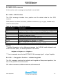
E.4.3 GSA – GPS DOP and Active Satellites ................................................ 48
E.4.4 GSV – Satellite Information .................................................................. 48
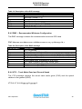
E.4.5 RMC – Recommended Minimum Configuration ................................... 49
E.4.6 VTG – Track Made Good and Ground Speed ...................................... 49
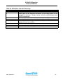
E.4.7 ZDA – Time and Date ........................................................................... 50
E.4.8 GST – GPS pseudorange noise statistics ............................................ 50
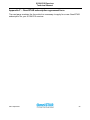
Appendix F – OmniSTAR subscription agreement form................................... 52
List of figures
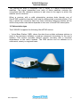
Figure 1: OmniSTAR 2100LR12 ............................................................................. 2
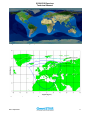
Figure 2: World coverage map for the OmniSTAR service ................................. 3
Figure 3: EMS spotbeam for coverage in Europe................................................ 3
Figure 4: Multipath.................................................................................................. 4
Figure 5: Zener Diode Installation ......................................................................... 7
Figure 6: 2100LR12 Mounting Details ................................................................. 10
Figure 7: LED Location and Colours................................................................... 12
Figure 8: 9 pin sub-D connector on data cable.................................................. 16
Figure 9: User and Antenna Cable ...................................................................... 17
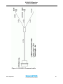
Figure 10: 2100LR12 Command cable ................................................................ 18
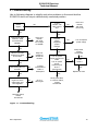
Figure 11: Troubleshooting ................................................................................. 19
Figure 12: Location and coverage area per satellite ......................................... 38
Figure 13: Location and coverage area per satellite ......................................... 39
List of tables
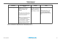
Table 1: Red LED Function .................................................................................. 12
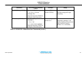
Table 2: 1st Yellow LED Function ....................................................................... 13
Table 3: 2nd Yellow LED Function ...................................................................... 13
Table 4: Green LED Function............................................................................... 14
Table 5: Pin-out for I/O Connector ...................................................................... 16
Table 6: 2100LR12 L-Band Receiver Commands............................................... 21
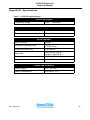
Table 7: 2100LR12 specifications ....................................................................... 36
Table 8: Worldwide satellite frequencies and symbol rates ............................. 38
Table 9: Reference stations on EMS ................................................................... 40
Table 10: Reference stations on EA-SAT ........................................................... 41
Table 11: Reference stations on AP-Sat ............................................................. 42
Table 12: Reference stations on AM-Sat ............................................................ 43
Table 13: Reference stations on Optus .............................................................. 43
Table 14: Reference stations on AMSC .............................................................. 44
Table 15: NMEA 0183 message options ............................................................. 45
Table 16: Description of the GGA message ....................................................... 47
Issue April 2001
v