1
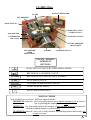
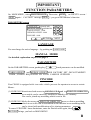
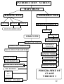
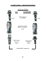
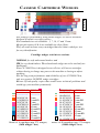
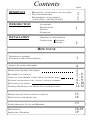
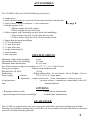
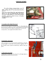
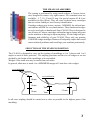
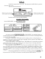
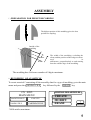
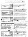
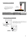
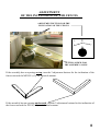
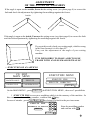
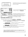
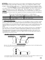
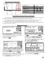
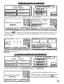
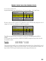
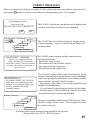
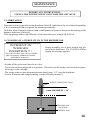
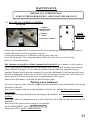
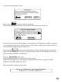
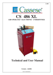
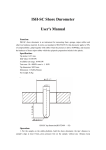
CS 4095 Ultra
Technical and User
Manual
V4 02/2002
CS 4095 Ultra
DIGITAL KEYBOARD
CLAMP
TOP PRESSER
BACK FENCES
EMERGENCY STOP
/ START BUTTON
MANOMETER
COMPRESSED
AIR VALVE
STAPLING BUTTON
CLAMP PRESSURE
ADJUSTMENT
TOP PRESSER
SPEED
ADJUSTMENT
BARREL
CARTRIDGE STOP
TOUCH - SCREEN
SYMBOLIC
BUTTONS
SELECTION OF VALUE BY REPEATED PUSHES .
RECORD OF A NUMERIC VALUE
ENTER
CLR
RETURN
RECORD OF ALL VALUES ON A SCREEN .
TO CLEAR A VALUE .
TO COME TO PRECEDENT VALUE .
NEXT
TO GO TO NEXT MENU .
?
HELP ( EXPLANATIONS )
MANUAL MODE
Your CS4095 can work on 3 different manual modes:
MINIMUM (manual) : the foot pedal pushed, the complete joining cy,cle is carried
out by pushing the stapling button once.
MEDIUM : the foot pedal pushed, the wedges of one stapling position are inserted
when the stapling button is pushed once.
MAXIMUM (manual) : the cycle is fully detailed: the stapling button inserts only one
wedge at a time.
A
IMPORTANT
FUNCTION PARAMETERS
On MAIN MENU, enter MAINTENANCE / Then enter NEXT on INPUTS screen /
NEXT again / CAUTION message NEXT / you get to the machine’s function
PARAMETERS screen
LANGUAGE : FRANÇAIS
MANUAL MODE : MINIMUM
TABLE OFFSET : 0000
WEDGES OFFSET : 0000
PINCODE : 0000
RETURN
1 2 3
4 5 6
7 8 9
0 CLR
NEXT
LANGUAGE
You can change the active language ...by pushing on LANGUAGE
MANUAL MODE
See detailed explanation on previous page A
PARAMETERS
On the PARAMETERS screen, pushing key
each parameter can be modified.
TABLE OFFSET and WEDGE OFFSET ARE FACTORY SET , DO NOT MODIFY
THEM , UNLESS REQUESTED BY YOUR CASSESE SUPPLIER .
PINCODE
Your CS4095 is equipped with two codes which prevent the operator to access to certain
Menus:
(1) CODE 2802 disactivates both access to JOINING FILE and to EXECUTE DIRECTLY
so no article can be cancelled, modified or added to the memory.
Nor can be joined any moulding which is not in file.
(2) CODE 2803 blocks the access to EXECUTE DIRECTLY menu, so that no moulding
which is not in file can be assembled on the machine or no moulding in file
can be joined with modifications of its joining paramaters.
To cancel PINCODE menu limitations, enter the Pincode once again, then
RETURN brings you back to MAIN MENU.
B
INTRODUCTION SCREEN
MAIN MENU
JOINING FILE
CREATE
MODIFY
CARTRIDGE FILE
ERASE
MAINTENANCE
LIST OF ARTICLES
INPUTS
OUTPUTS
EXECUTE
PARAMETERS
EXECUTE FILE
EXECUTE DIRECTLY
MOULDING PARAMETERS
HAMMER
CHANGE
LANGUAGE
MANUEL MODE
FINE TUNE
AUTO/MANUAL
WITH /OUT SPACERS
PINCODE
TABLE OFFSET
WEDGE OFFSET
SEE BARREL
45°
30°
22.5°
WEDGE PUSHER
PROGRAMME OF
CS 4095
VERSION 3
C
CS 4095 ULTRA AIR LINE FITTINGS
Advised way of fitting :
USA
STANDARD
Male Connector
on Machine
Z 675
Z 675
quick release (Q/R)
female air connector
Z 749
Q/R US male
connector
Standard hose
connector
Z 701
Z 556
AIR SOURCE (compressor)
D
CASSESE CARTRIDGE WEDGES
S
O
F
T
H
A
R
D
The joining is performed by using metal wedges, a Cassese invention,
designed to ensure very tight corners.
Five standard sizes are available : 5, 7, 10, 12 and 15 mm.
On special request #3 & 4 are available for slips (filets).
They all come in throw-away cartridges that are colour-coded per size
for easy identification.
Cartridge wedges exist in two versions :
NORMAL for soft and normal timbers and
HW for very hard timbers. These hardwood wedges are to be used only on
hardwoods.
Your CS 299M Ultra is designed to use all sizes of Cassese cartridges
without having to change any parts on the machine or having to adjust
anything.
For the long term performance and reliability of your CS 299M Ultra,
only use genuine CASSESE wedge cartridges.
Beware of bad quality copies that would cause technical problems and
would age your machine prematurely.
REFERENCE
TYPE
-----------------------
-------------------
-----------------------
-------------------
30305NCOI
31305BDCO
30307NCOI
31307BDCO
30310NCOI
31310BDCO
30312NCOI
31312BDCO
30315NCOI
31315BDCO
5 mm
5 mmBD
7 mm
7 mmBD
10 mm
10 mmBD
12 mm
12 mmBD
15 mm
15 mmBD
Boxes of 6 cartridges (app. 275 wedges)
(1650 wedges / box)
REFERENCE
30403NCOI
30404NCOI
304 05 NCOI
314 05 BDCO
304 07 NCOI
314 07 BDCO
304 10 NCOI
314 10 BDCO
304 12 NCOI
314 12 BDCO
304 15 NCOI
314 15 BDCO1
TYPE
3 mm
4 mm
5 mm
5 mm BD
7 mm
7 mm BD
10 mm
10 mmBD
12 mm
12 mmBD
15 mm
15 mmBD
Boxes of 40 cartridges (app. 275 wedges)
(11000 wedges / box)
Contents
IMPORTANT
PAGES
- DESCRIPTION - TOUCH SCREEN - MANUAL MODE
- FUNCTION PARAMETERS
- PROGRAMME OF CS 4095 VERSION 3
A
B
C
D
- CS 4095 ULTRA AIR LINE FITTINGS
INTRODUCTION
- ACCESSORIES
- SPECIFICATIONS
- OPTIONS
- GUARANTEE
INSTALLATION
- ASSEMBLY OF THE KEYBOARD
- CONNECTIONS PNEUMATIC
ELECTRIC
1
2
HOW TO USE
THE MEANS OF ASSEMBLY
SELECTION OF THE STAPLING POSITION
3
START UP & LOADING THE BARREL
4
PREPARATION FOR PRESET RECORDING
EXAMPLE AND ENTRY OF AN ARTICLE WITH 3 STAPLING POINTS
5
5-6
7-8
8-9
9 -10
11-12
MODIFICATION & CANCELLATION OF AN ARTICLE
PRESET FOR VOLUME PRODUCTION
13
14
SCREEN MESSAGES - FAULTS AND REMEDIES
15
MAINTENANCE
SPARE PARTS - DRAWINGS
16-18
19
RECORDING OF AN ARTICLE
CHOICE OF A TOP
PRESSER - USE OF THE SET OF SPACER - BARS
SETTINGS : INCLINATION OF THE
FENCES , ANGLE OF ASSEMBLY
EXECUTION OF AN ARTICLE
ACCESSORIES
The CS 4095 is delivered with the following accessories:
- 1 trapdoor key.
- 1 quick release female air connector for the male one that is on machine
- 1 quick release US male connector / 1 hose connector
- 1 triangle support with:
1 Black triangle (for hard woods).
1 White triangle (for normal wood).
- 1 rubber support with, depending on the form of the mouldings:
1 Green rubber stop (for 30 & 45 mm hard woods).
2 Yellow rubber stops (for 45 & 30 mm normal wood).
- 1 Spacer bars for small mouldings.
- 1 x 2.5 mm Allen key.
- 1 x 3 mm Allen key.
- 1 x 5 mm Allen key .
- 1 wedge removing tool.
- 1 spare hammer.
- 1 tube of grease.
SPECIFICATIONS
See page D
Minimum width of the moulding :
3 mm
Maximum width of the moulding :
130 mm
Minimum frame dimensions
:
85 x 85 mm
Size of the Cassese wedges in cartridges of 275 : 5, 7, 10, 12 and 15 mm.
Two types of staples
:
normal wood and hard wood.
Weight of the CS 4095
:
120 kg.
Dimensions
: Width without desk = 45 cm, Depth = 50 cm, Height = 114 cm
Power supply
- electric
:
220 V or 110 V single phase.
- pneumatic: compressed air at 6 - 7 bars, consumption 5 litres per cycle.
Air preparation
:
pressure reducer + manometer, connection by tube of 8
mm
internal diameter.
OPTIONS
- Rotating extension table .
- Special clamps for furniture mouldings
- 6 sided frame attachements
- 8 sided frame attachements
GUARANTEE
The CS 4095 is guaranteed for one year, spare parts and labour, against all manufacturing faults.
Wearing parts and those damaged by use which is not in accordance with that laid down by this document are excluded from the guarantee.
1
INSTALLATION
For safety during transportation, your CS
4095 s sliding table ST has been blocked with a
screw S.
This screw is just behind the angle adjustement
button AA . It is very important that you remove
the screw S with allen key N° 5 provided with the
machine, and fix it back in case of further
transportation of your
CS 4095 .
’
AA ST
S
1 Assembly of the digital keyboard
Fit the keyboard support S into the sleeve A , then tighten the
sleeve from the inside with a flat 30 mm spanner (not supplied). M
Put the keyboard in the support and position it to suit your
N
work position , then tighten the handles M & N .
Sleeve
S
A
2 Pneumatic connection
After opening the access trap with the trapdoor key , the compressor output is connected to the pressure regulator PR of
the CS 4095 with a quick fit connection, which is also supplied.
PR
3 Electrical connection
Connect the CS 4095 to a 220 volt or 110 volt single phase as
appropriate grounded electrical socket.
2
THE MEANS OF ASSEMBLY
The joining is performed by using metal wedges, a Cassese invention, designed to ensure very tight corners. Five standard sizes are
available : 5, 7, 10, 12 and 15 mm. On special request #3 & 4 are
available for slips (filets). They all come in throw-away cartridges
that are colour-coded per size for easy identification.
Cartridge wedges exist in two versions : NORMAL for soft and normal timbers and HW for very hard timbers. These hardwood wedges
are to be used only on hardwoods.Your CS 4095 Ultra is designed to
use all sizes of Cassese cartridges without having to change any parts
on the machine or having to adjust anything. For the long term performance and reliability of your CS 4095 Ultra, only use genuine
CASSESE wedge cartridges. Beware of bad quality copies that would
cause technical problems and would age your machine prematurely.
SELECTION OF THE STAPLING POSITION
The CS 4095 is designed to carry out the joining of mouldings at 1 to 3 places with 1 to 9
staples at each of these positions. The stapling positions and the size of wedges to use are
decided by the height of the mouldings to be assembled.
Wedges of the same size may be stacked on each other.
In general, allowance is made for a MINIMUM margin of 2 mm above the wedges.
2 mm MINIMUM
2 mm MINIMUM
10mm
2 mm MINIMUM
10mm
7mm
10mm
7mm
12 mm
In all cases stapling should be carried out as close as possible to the highest parts of the
moulding.
3
START UP
Switch the compressed air valve ON. The manometer should indicate a pressure
between 6 and 7 bars.
Turn the red start button and
Number of cycles carried out
by the machine since day 1.
UNDERPINNER 4095
CYCLES : 00000055
Number of wedges inserted
by the machine since day 1
WEDGES: 00000082
TOUCH THE SCREEN TO CONTINUE
.
Touch the screen to get to the MAIN MENU.
LOADING THE BARREL
On the MAIN MENU , enter CARTRIDGE FILE
CS 4095
MAIN MENU
MAINTENANCE
JOINING FILE
EXECUTE
CARTRIDGE FILE
N°5
N°7
N°10
N°12
N°15
5HW
7HW
10HW
12HW
15HW
EMPTY
C1
C2
5
7
10
C4 12HW
C5 15HW
C3
ENTER
?
As soon as you enter CARTRIDGE FILE on MAIN MENU , the machine brings out
its barrel and presents the channel # 5 . Each channel can receive all sizes of cartridges both for
normal and hardwoods (HW).
Lift up the CARTRIDGE STOP and insert the cartridge you have selected under it in
channel # 5. Then enter on the screen the type of cartridge you have inserted. The CS4095 will
check if the cartridge contains wedges.
Select another channe1 on the digital screen. The machine wi11 present the new channe1
selected. Proceed in the same way as for the previous channel; insert a cartridge and inform
the machine on the type of cartridge inserted.
You can declare a channel EMPTY even if you put a cartridge in this channel. In this
case, the CS4095 will not use the cartridge in this channel. All channels in which there will be
no wedge left during work will be declared automatically EMPTY by the CS4095.A channel
physically EMPTY or with a cartridge not containing any wedge cannot be declared as having
wedges in.
After having loaded the barrel with Cassese cartridges, push the key ENTER on the
keyboard screen. The CS4095 will return to the initial position (MAIN MENU).
4
ASSEMBLY
1 ) PREPARATION FOR PRESET RECORDING
The highest portion of this moulding gives the best
position for stapling.
Outside of the
moulding
0
Position
Width
The width of the moulding, excluding the
rebate, and the position of the wedge are measured
in
millimetres, perpendicularly to and starting
from the outside edge of the moulding.
The moulding has a reference number of 8 digits maximum.
2)
RECORDING OF AN ARTICLE
To create an article* containing all the assembly data for a type of moulding, go to the main
menu and press the JOINING FILE
key followed by the CREATE key.
CS 4095
MAIN MENU
MAINTENANCE
JOINING FILE
EXECUTE
CARTRIDGE FILE
GESTION DES ARTICLES
CREATE
MODIFY
ERASE
?
RETURN
*1000 articles maximum .
5
Every numeric information should be confirmed with the
key. Otherwise the keyboard will keep the previous information.
1 2 3
4 5 6
7 8 9
0 CLR
REFERENCE TO CREATE
00000124
- Enter the reference number of the moulding. In
case of mistake, press CLR and start again.
Confirm with key
- Page 1 of the Joining Parameters comes up.
RETURN ?
REFERENCE
00000124
MOULDING WITH :
011
WHITE TRIANGLE
SPACER
PAGE 2
ENTER
MOULDING WIDTH
1
POSITION
SIZE
NOMBRE
2
3
005 000 000
5
5
5
0
0
0
PAGE1
ENTER
POSITION 1
1 2 3
4 5 6
7 8 9
0 CLR
RETURN
011
- Enter the moulding’s width in mm, confirm with
key
- By pushing several times on the key presenting
the top pressor types proposed by the machine,
leave it on the top pressor type you want. Pushing
on key SPACER (you will darken this key),
and the CS4095 will ask automatically for the
spacer bars for this moulding. Pushing PAGE 2
key, you access to the second and last page of
joining data.
?
- On the numeric screen, enter the distances of the
joining positions from the back of moulding in
mm , from the closest position (Pos 1) (smallest
value) to the furthest position (biggest value).
Confirm with
- To select the wedge sizes to be inserted, enter SIZE
key . A new screen will appear:
1 2 3
4 5 6
7 8 9
0 CLR
RETURN
?
POSITION 2 POSITION 3
7
5
WEDGE
5
SELECTION
5
7
10
12
15
5HW 7HW 10HW 12HW 15HW
SEE BARREL
Moulding Width
ENTER
011
1
2
POSITION
SIZE
NUMBER
005 00
7
5
1
0
PAGE1
ENTER
3
00
5
0
?
1 2 3
4 5 6
7 8 9
0 CLR
RETURN
?
- Enter the position selected (key darkens) and
enter the size decided for this position. You can
also check the sizes available in the barrel.
After having entered the sizes for the positions,
push ENTER key to come back to the previous
screen of joininy data. If you wanted only 2
positions, the 3RD position will still keep a
wedge size, but the machine will not take it into
account if there is no value for 3RD stapling
position).
With the
key , bring the selection rectangle
to the wedge number and enter the quantity of
wedges you want in this position . Confirm the
number with
.Once you enter all position
values and wedge numbers , push ENTER key.
RETURN Cancels the recording and brings you
back to FILES MANAGER menu .
6
3) THE CHOICE OF A TOP PRESSER
Check that the run between the
top of the moulding and the bottom
of the presser is not more than
50 mm ( 2” )
BLACK TRIANGLE PRESSER
WHITE TRIANGLE PRESSER
GREEN RUBBER TIPS
YELLOW RUBBER TIPS
50 mm
MAXIMUM
HARD WOOD
SOFT WOOD
HARD WOOD
SOFT WOOD
Fixing in holder
with a 2.5 mm Allen key
30 and 45 mm
30 and 45 mm
4 ) THE USE OF THE SET OF SPACER BARS
If small mouldings are being assembled which are of a
smaller height than the fences, the use of the set of
spacer bars supplied is essential.
Moulding
INCORRECT
Stop
Presser
Wedge distributor
CORRECT
Set of spacer bars
7
ADJUSTMENT
OF THE INCLINATION OF THE FENCES
ADJUSTMENT BUTTON FOR THE
INCLINATION OF THE FENCES
+
0
-
SETTING SCREW FOR
THE ASSEMBLY ANGLE
If the assembly has an opening on top, turn the 2 adjustment buttons for the inclination of the
fences towards the MINUS (-) by an identical amount.
If the assembly has an opening underneath, turn the 2 adjustment buttons for the inclination of
the fences towards the PLUS (+) by an identical amount.
8
ADJUSTMENT
OF THE ANGLE OF ASSEMBLY
If the angle is open on the outside, Screw in the setting screw (see photo page 8) to correct the
fault and check the adjustment by tightening the mouldings against the fences.
Outside
Inside
If the angle is open on the inside, Unscrew the setting screw (see photo page 8) to correct the fault
and check the adjustment by tightening the mouldings against the fences.
If you get this result, check your cutting angle, which is wrong
in this case because it is less than 45°.
Carry out the adjustment of the angle of your cutting
machine.
IT IS IMPOSSIBLE TO MAKE A RECTANGLE
FRAME WITH ANGLES SMALLER THAN 90°.
5)
EXECUTION OF AN ARTICLE
CS 4095
MAIN MENU
MAINTENANCE
EXECUTION MENU
EXECUTE FILE
EXECUTE
EXECUTE DIRECTLY
JOINING FILE
CARTRIDGE FILE
RETURN
?
On the MAIN MENU , press EXECUTE .In EXECUTION MENU , there are 2 possibilities
:
1 ) EXECUTE FILE to execute a moulding which is in the memory of the machine . In
this case , enter the moulding number , confirm with
key .
In case of mistake , press CLR . RETURN key brings you back to the previous menu .
1
4
REFERENCE TO EXECUTE
7
00000124
0
EXECUTE FILE
2
5
8
3
6
9
CLR
Enter the moulding number
and confirm with
RETURN ?
9
PLEASE , USE THE BUNG
The CS4095 will request you to put the memorised
top pressor pad on the machine. Press anywhere on
the screen to continue.
WHITE TRIANGLE
WITH THIS MOULDING
Touch the screen to continue
Moulding : 00000124
Width :
011
1
POSITION
SIZE
NUMBER
2
3
005 00
7
5
1
0
EXECUTE
EXECUTION
MANUAL
011
1
2
005 000
7
5
1
0
Position
Taille
Nombre
PUSHER
45°
00
5
0
3
000
5
0
A new screen with al1 joining parameters for this
moulding will appear. Press EXECUTE .
RETURN
Fine Tune
- 1 mm
+ 1mm
MOULDING : 00000124
Moulding Width
1 2 3
4 5 6
7 8 9
0 CLR
SPACER
RETURN
The machine will immediately prepare itself to
join this moulding. If the spacer bars were
memorised for this profile number, there will be
additional gap on the machine so to put the
spacers behind the mouldings.
?
The machine offers two modes of joining: MANUAL or AUTOMATIC
The CS4095 always proposes first the Manual mode. Pressing the key MANUAL ,
you change it AUTOMATIC mode or the opposite way.
AUTOMATIC mode : pushing the foot pedal, the machine clamps the
mouldings and inserts all the wedges of the joining process.
MANUAL mode: pushing the foot pedal, the machine clamps the mouldings.
To insert the wedges, press the (black) stapling button.
(There are 3 manual modes possible. This is set up in the Function parameters of
the machine. See the first pages of the instructions manua1).
Both in AUTOMATIC and MANUAL modes, the foot pedal must remain
pushed during the whole joining cycle.
10
PUSHER key allows you to correct, if you detect a bad loading of the cartridge into
the distributor head. The FINE TUNE keys allow you to adapt the CS4095 to the
changes of the moulding width (up to +/- 2 mm) from the memorised standard width.
Pressing the 45° key, you can adapt the machine to join 6-sided (cut at 30°)
or 8-sided (cut at 22,5°) frames with the same mouldings.(You need to insert special
angle attachments in front of the sliding table. These attachments are available for
CS4095 as optional accessories). When joining 6 or 8-sided frames, we advise not to
use the spacer bars so not to lose capacity in terms of maximum width of moulding to
be joined.
Please note the following limitations for 6 - 8 sided frames:
Moulding width maximum Minimum distance of the wedge
6-sided ( 30° )
120mm (app rox. 4" 7/8)
3mm from rebate
8-sided (22.5°) 115mm (approx. 4" 5/8)
7mm from rebate
(2) EXECUTE DIRECTLY:
This execution mode allows the operator to join mouldings without recording in FILE
memory. In this mode, the machine reminds automatically the joining process of the
last moulding executed which allows the operator to go on any series production after
shutting down the machine for a while, without calling up the moulding reference
again.
In this mode, it is also possible to modify some joining parameters for a moulding in
file at the time of execution, without modifying the parameters memorised in file.
This mode permits the operator also to find a moulding number in the articles list
(JOINING FILE + MODIFY+ LIST OF ARTICLES), to come back and execute it
immediately in the direct mode.
5 ) EXAMPLE AND ENTRY OF AN ARTICLE WITH 3 STAPLING POINTS
2 mm MINIMUM
2 mm MINIMUM
2 mm MINIMUM
36 mm
16 mm
14 mm
POSITION OF STAPLES
Because of its width, this moulding will be assembled with 3 stapling points, located on the highest portions.
The 2 mm rule gives us the maximum penetration heights.
As the staples must penetrate to at least 2/3 of each height, here is the size and number of staples to be used
for each point, staples of the same size being able to be stacked on each other.
11
MEASUREMENT OF THE WIDTH
The rebate
is not counted
90°
0
0
74 55 25
( mm )
79 mm
ARTICLE No.
WIDTH
POSITION
WEDGE SIZE
NUMBER OF WEDGES
PRESSER TIP
SPACER BARS
538
79 mm
25
55
74
10
7
12
3
2
1
GREEN 45 mm
NO
MEASUREMENT OF THE POSITION OF THE WEDGES
The width of the moulding not counting the rebate, and the position of the wedges are measured in
millimetres, perpendicular to and starting from the outside edge of the moulding.
The stapling points are projected perpendicularly onto the line of measurement of the width. The
measurement of each point starts from the outside edge up to each intersection with the 45° cut.
Once all the necessary information has been obtained, a table is made up before entry. The article number
is totally arbitrary in this example.
1
4
7
0
REFERENCE TO CREATE
00000538
2 3
5 6
8 9
CLR
RETURN ?
On the MAIN MENU,
press JOINING FILE, followed by CREATE.
Enter the moulding number 538.
Confirm with
MouldingWidth :
079
1
POSITION
SIZE
NUMBER
PAGE1
2
3
025 055 074
10 7
12
3
2
1
ENTER
1 2 3
4 5 6
7 8 9
0 CLR
RETURN ?
REFERENCE : 00000538
Moulding Width : 079
GREEN RUBBER 45
SPACER
PAGE 2
ENTER
1
4
7
0
2 3
5 6
8 9
CLR
RETURN ?
Enter the width of the profile in mm. Confirm
with
.
Press the window WHITE TRIANGLE
until it comes to GREEN RUBBER 45.
As no spacers are needed for this moulding
don’t press the SPACER key.
Press PAGE 2 to go to page 2
POSITION 1 POSITION 2
10
7
POSITION 3
12
WEDGE SELECTION
5
7
10
12
15
5HW 7HW 10HW 12HW 15HW
SEE BARREL
ENTER
On page 2, enter the values of the positions. After
?
Each value and
key, move to the next value
Enter the wedge quantities and confirm with
with VERTICAL ARROW. Press SIZE to
When all parameters are like on your table for
access to the choice of wedge sizes or each
this moulding, press ENTER .
position. Press active position, then wedge size for
it. Press ENTER to come back to page 2.
12
MODIFICATION D’ARTICLE
CS 4095
MAIN MENU
MAINTENANCE
FILES MANAGER
CREATE
MODIFY
ERASE
EXECUTE
JOINING FILE
CARTRIDGE FILE
?
RETURN
On the MAIN MENU , press JOINING FILE , then MODIFY .
1 2 3
4 5 6
7 8 9
0 CLR
REFERENCE TO MODIFY
00000538
REFERENCE 00000538
Moulding Width : 079
GREEN RUBBER 45
SPACER
RETURN ?
ARTICLES LIST
PAGE 2
ENTER
1 2 3
4 5 6
7 8 9
0 CLR
RETURN ?
To check the moulding in file , press ARTICLES LIST . Enter the moulding number and
confirm with
, to access to first page of joining data of this reference numbers .You
can change now any joining parameter of this moulding like in process of recording an
article ( page 6 ) .
Moulding Width :
079
1
POSITION
SIZE
NUMBER
PAGE1
2
3
025 055 074
10
10 10
3
1
1
ENTER
1 2 3
4 5 6
7 8 9
0 CLR
POSITION 1 POSITION 2 POSITION 3
10
10
10
WEDGE SELECTION
5
7
10
12
15
5HW 7HW 10HW 12HW 15HW
SEE BARREL
ENTER
?
RETURN ?
Enter the new joining parameters on page 1 and 2 and memorise the new parameters with
ENTER key on page 2 .
CANCELLATION OF AN ARTICLE
CS 4095
MAIN MENU
MAINTENANCE
JOINING FILE
FILES MANAGER
CREATE
MODIFY
ERASE
EXECUTE
CARTRIDGE FILE
On the MAIN MENU , press JOINING FILE
REFERENCE TO ERASE
00000033
ARTICLES LIST
1 2 3
4 5 6
7 8 9
0 CLR
RETURN ?
?
RETURN
, then ERASE .
To check the list of mouldings in file , press
ARTICLES LIST . Enter the moulding number
to be cancelled and confirm with
key .
The machine will ask you again if you are sure .
13
PRESET FOR VOLUME PRODUCTION
Let us return to article 538.
Its penetration depths have defined the use of 3 sizes of wedge : 10, 12 and 7 mm.
ARTICLE No.
538
WIDTH
79 mm
POSITION
25
55
74
WEDGE SIZE
10
7
12
NUMBER OF WEDGES 3
2
1
TOP PRESSER TYPE
GREEN 45 mm
SPACER BARS
NO
We now wish to create an article 539, identical to article 538 but only using one size of
wedge, the 10 mm size, which gives sufficient penetration:
ARTICLE No.
539
WIDTH
79 mm
POSITION
25
55
74
WEDGE SIZE
10
10
10
NUMBER OF WEDGES 3
2
1
TOP PRESSER TYPE
GREEN 45 mm
SPACER BARS
NO
The difference between these two articles is therefore the NUMBER and the SIZE of
wedges.
Let us execute these two articles, in MANUAL MODE, timing how long it takes for each
to assemble a corner .
Results:
Article 538 takes 9. 3 seconds.
Article 539 takes 4 seconds.
This demonstration enables us to conclude that the best productivity is obtained by the use of
a minimum number of wedge sizes for the assembly. For the mass production of frames, the
barrel of the CS 4095 may be loaded entirely with wedges of the same size.
14
SCREEN MESSAGES
There is a continuous help function on the CS 4095, which can be accessed either at your request by
pressing the ? button or if there is an incident or a programming error. For example:
File number
00000666
DOES NOT EXIST
DO YOU WANT TO CREATE IT?
YES
The CS 4095 is informing you that the article number that
you have entered for execution is not referenced.
NO
ONE OR MORE CARTRIDGES
C1
SIZE 5
ARE EMPTY .
C2
C3
C4
C5
EMPTY
The CS 4095 has detected the absence of wedges in one
or more cartridges , warns you about this and helps you
to replace them.
7
10
12
15
LOAD
BARREL
INSUFFICIENT PRESSURE
There is no enough pressure air
for the machine to work normally
check the air arrival . Once the problem
is solved , the machine comes back to
the last screen .
WARNING !!!
CLAMPING SAFETY ACTIVATED !
Either there are no muoldings on the
machine or the moulding width is far
from the standard width of this
moulding number .
BARREL DISPLAY
C1
C2
C3
C4
C5
The CS 4095 cannot operate without compressed air.
Check the following:
- That the air valve is open,
- The connection to the pressure reducer,
- The output from the compressor,
- The operation of the compressor.
The CS 4095 is fitted with an end of run detector for the
clamp, so that stapling is stopped if there are no mouldings.
If the message appears when there are mouldings in place
on the machine, the fault could be because:
- The pressure of the clamp is too strong compared to the
hardness of the moulding:
Use the button for adjusting the pressure of the clamp.
- The dimensions of the moulding are smaller than those
recorded in the article that has been loaded.
5
7
10
12
15
The types of cartridges loaded in the CS 4095 may be easily
checked ,visually on the screen. The cartridge to be used
may then be selected.
RETURN
...... And many other screen messages help and advise the operator
during all the steps of CS 4095’s function .
15
MAINTENANCE
BEFORE ANY INTERVENTION,
UNPLUG THE POWER SUPPLY AND CLOSE THE AIR VALVE
1 ) LUBRICATION
From time to time, remove the wedge distributor (block H ) and clean it (by air) without dismantling
it.It is recommended that you grease the hammer periodically.
To do this, block H must be removed, and a small quantity of grease is then put in the housing of the
hammer at the base of block H.
If the top plunger slides with difficulty, oil the horizontal axes, using SAE 20/40 oil.
2) CLEARING OF A WEDGE STUCK IN THE DISTRIBUTOR
INCIDENT IN
WEDGES
INSERTION !!!
STOP THE MACHINE AND CHECK IF THERE
ARE NO WEDGES JAMMED IN WEDGE
DISTRIBUTION BLOCK.
During assembly, one or more wedges may get
stuck in the distributor. The CS 4095 will then
display the message opposite.
-Switch off the power and close the air valve.
-Try to remove the cartridge that is in position. If it resists, use the wedge removal tool to replace
the wedge in the cartridge.
-The wedge remover must not penetrate more than 6 mm ( 1/4’’) into the distributor.
-In case of hammer and wedge jamming, see the following section (3).
WEDGE REMOVING TOOL
6mm MAXIMUM ( 1/4’’ )
DISTRIBUTOR
( BLOCK H )
WEDGE EXIT
16
MAINTENANCE
BEFORE ANY INTERVENTION,
UNPLUG THE POWER SUPPLY AND CLOSE THE AIR VALVE
3 ) IN CASE OF A WEDGE JAMMING
PLUNGER
WEDGE
DISTRIBUTOR
(BLOCK H)
A
SLIDING
TABLE
BLOCKING SCREW
D
GF1
SCREW
POSITIONS
BLOCK H
GF2
F
E
B
C
Remove the cartridge that is in position in the active channel by moving the barrel so that its
stands sufficiently out of the machine’s structure.
Loosen the blocking screw of Block H with the 3mm Allen key.
Next, lift the plunger. The wedge distributor (block H) will come out of its housing.
Remove it from the machine.
The hammer (wedge driver blade) jammed in the block H, try to remove it with a pair of
pliers. If not possible, unscrew the 2 central screws (GF1 & GF2) that hold the fixed (square)
guide of Block H in place. Use for this the smaller (2.5mm) Allen key supplied with the
machine. Remove the fixed guide completely to free the old hammer. If still not possible to get
rid of the old hammer, remove the 4 screws (A,B,C,D) and open the block H. (Two factory set
locator pins E & F allow the plates to be re-positioned precisely again),
Remove the old hammer. Assemble the block H back again.
Putting a new hammer:
Put a drop of grease (tube of grease supplied with the machine) in the bottom hole of the wedge
distributor (block H).
Insert a new hammer into the wedge distributor from the top, with the hole of the hammer
downwards.
Re-position the wedge distributor in its housing on the machine with the window towards the
cartridge.
If the upper end of the hammer stays out of the block H, push it fully in with a piece of wood or
moulding.
Now turn on the power and air supply to the machine.
On the MAIN MENU, press MAINTENANCE
Then press NEXT, on the next two screens.
17
You will get the following screen:
CAUTION !!!
You are entering the machine’s function
parameters. Any change of these may modify
the machine functions.
RETURN
NEXT
Press on key
which symbolises a hammer.
The machine is ready for hammer change and the following screen comes up:
CHANGE THE HAMMER
Replace the hammer, and put a piece of wood or
mouldings under the top presser and press
and stapling button at the same time to finish
the change process.
RETURN
Put any of the top presser ends (triangle or round rubber) on the machine and place a big piece
of wood (hardwood is better) on the block H, on the machine. (Maxi distance between the top
presser and the moulding must be 50mm (2").)
Now, keeping
-key pressed on the machine, push the stapling (black) button at the
same time; the machine will simulate a wedge insertion so that the new hammer can take its
position in the mechanism automatically.
Press on RETURN on the screen.
Now, turn off the machine from the power and air supply.
Tighten the blocking screw of the block H, using the 3mm Allen key (supplied with the
machine). No need to tighten too much.
Now the machine is ready to work again.
AFTER ANY INCIDENT, IF THE HAMMER REMAINS
IN BLOCK H , YOU MUST CHANGE IT.
18