1
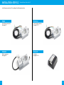
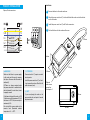
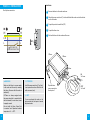
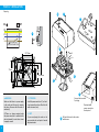
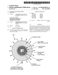
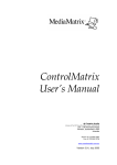
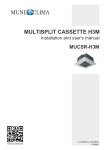
INSTALLATION MANUAL
SAFERA Airis Stove Guard
Power Control Units:
PCU5.1-P-Airis
PCU3-Airis
PCU3-W-Airis
PCU5.1-U-Airis
20801 V4.5.0 ENG AIRIS
CONTENTS
1.PREPARATIONS
1. Preparations
ѥѥ WARNING
2. Installation
Read user and installation manual before
using or installing the appliance.
3. Installation troubleshooting
4. Optional: Installing the Water Leakage
Sensor
5. Manual adjustment mode
WARNINGS
Follow these instructions carefully and
pay particular attention to the instructions
marked in the following way:
ѥѥ WARNING
Follow instructions marked with a
warning accurately to prevent injury to
persons and damage to property.
⚐⚐ ATTENTION
Follow instructions marked with a note
carefully to prevent damage to property.
ѧѧ HINT
Hints give you useful advices on using the
appliance.
Install and check the application
according to the instructions. SAFERA is
not liable for any damages or expenses
caused by inappropriate installation.
1.2 Package content
Check the product and the contents of the package before installation:
Transparent front cover
10 x Color labels
Power control unit Ⓒ
(various models available)
Cleaning pad
Check that the Stove Guard is compatible
with the cooker (see section 1.1).
If the network cable is damaged, it must
be replaced by the service personnel of
the manufacturer or their representative
to avoid hazards.
All electrical connections must be carried
out by a qualified electrician.
⚐⚐ ATTENTION
If the appliance was stored in a cold
space, it must be allowed to warm up to
room temperature before connecting it to
electric network.
1.1 Compatibility
SAFERA Stove Guard is compatible with
most electrical cookers, hobs and ovens
meant for household use:
•
•
•
•
Traditional cast-iron cookers and hobs
Ceramic cookers and hobs
Induction cookers and hobs
Cookers and hobs equipped with a
timer, afterheat indicator, child proof
lock or integrated switch-off system
2 x Batteries for
sensor unit (AA/
LR6)
Sensor unit Ⓐ
with mounting
bracket Ⓑ
Optional mounting
screws (2x)
User and Installation Guides
ѥѥ WARNING
Please contact your vendor if you notice
anything unusual about the appliance.
SAFERA Airis is compatible with cookers
no wider than 90 cm, see chapter 2. Installation step 2/2.
2
3
INSTALLATION - STEP 1/2
Mount the Power Control Unit Ⓒ
Install the power control unit Ⓒ according to the following instructions.
4
PCU3
PCU5.1-U
Fixed 3-phase connection.
See pages 6-7.
Fixed 1-phase connection.
See pages 10-11.
PCU3-W
PCU5.1-P
Perilex-connectors.
See pages 8-9.
3-pin plug.
See pages 12-13.
5
Installation
PCU3 - INSTALLATION
Fixed 3-phase connection.
IN
OUT
PE
PE
N
L/N
MAX
230V 16A
400V 10A
L
L2
MAX
230V 16A
400V 10A
L
L3
MAX
230V 16A
400V 10A
L
L1
1
Remove the fuses to the cooker and oven.
2
Mount the power control unit Ⓒ on the wall behind the cooker or into the cabinet
next to the cooker.
3
Couple the protective earth first (PE).
4
Couple the other wires.
5
Put back the fuses for the cooker and the oven.
OFF
130 mm
180 mm
MICRO DISCONNECTION
60 mm
IN
5 x 2,5 mm2
0,7 m
ѥѥ WARNING
⚐⚐ ATTENTION
Make sure that there is no power supply
to the cooker and the oven by removing
their fuses. Also ensure that the cooker is
switched off.
Power control unit Ⓒ requires a neutral
wire to operate.
OUT-wires are always energized when
the power control unit is connected to the
electrical network. If a wire is loose, it must
be properly covered.
If the element voltage of the cooker is 400
V, the fuse can only be maximum of 10 A. If
the element is 230 V, the fuse can only be
maximum of 16 A.
Install the power control unit Ⓒ so that it
is not exposed to moisture. Check that all
cables can move freely.
Optional
water sensor
connection.
See chapter 4.
OUT
5 x 2,5 mm2
1,3 m
ѧѧ HINT
If you are replacing the cooker or the
power control unit, see chapter 5 manual
adjustment mode.
Do not install the power control onit to
excessive heat: Operational ambient
temperature is +5 … +40°C.
6
7
Installation
PCU3-W - INSTALLATION
3-phase, Perilex-connectors.
1
Remove the fuses to the cooker and oven.
2
Mount the power control unit Ⓒ on the wall behind the cooker or into the cabinet
next to the cooker.
IN
OUT
3
Install the power control unit Ⓒ with Perilex-connectors.
PE
PE
4
Put back the fuses for the cooker and the oven.
N
L/N
MAX
230V 16A
400V 10A
L
L2
MAX
230V 16A
400V 10A
L
L3
MAX
230V 16A
400V 10A
L
L1
700 mm
OFF
MICRO DISCONNECTION
66 mm
313 mm
ѥѥ WARNING
⚐⚐ ATTENTION
Make sure that there is no power supply
to the cooker and the oven by removing
their fuses. Also ensure that the cooker is
switched off.
Power control unit Ⓒ requires a neutral
wire to operate.
OUT-wires are always energized when
the power control unit is connected to the
electrical network. If a wire is loose, it must
be properly covered.
If the element voltage of the cooker is 400
V, the fuse can only be maximum of 10 A. If
the element is 230 V, the fuse can only be
maximum of 16 A.
Do not install the power control onit to
excessive heat: Operational ambient
temperature is +5 … +40°C.
8
Install the power control unit Ⓒ so that it
is not exposed to moisture. Check that all
cables can move freely.
ѧѧ HINT
146 mm
Optional
water sensor
connection.
See chapter 4.
126 mm
If you are replacing the cooker or the
power control unit, see chapter 5 manual
adjustment mode.
280 mm
9
Installation
PCU5.1-U - INSTALLATION
Fixed 1-phase connection.
IN
OUT
PE
PE
L/N
N
L
L
1
Remove the fuses to the cooker and oven.
2
Mount the power control unit Ⓒ on the wall behind the cooker or into the cabinet
next to the cooker.
3
Couple the protective earth first (PE).
4
Couple the other wires.
5
Put back the fuses for the cooker and the oven.
OFF
230V MAX. 25A
MICRO DISCONNECTION
130 mm
180 mm
60 mm
IN
3 x 4 mm2
ѥѥ WARNING
⚐⚐ ATTENTION
Make sure that there is no power supply
to the cooker and the oven by removing
their fuses. Also ensure that the cooker is
switched off.
Install the power control unit Ⓒ so that it
is not exposed to moisture. Check that all
cables can move freely.
OUT-wires are always energized when
the power control unit is connected to the
electrical network. If a wire is loose, it must
be properly covered.
ѧѧ HINT
Optional water
sensor connection.
See chapter 4.
OUT
3 x 4 mm2
If you are replacing the cooker or the
power control unit, see chapter 5 manual
adjustment mode.
Do not install the Power Control Unit
to excessive heat: Operational ambient
temperature is +5 … +40°C.
10
11
PCU5.1-P - INSTALLATION
3-pin plug.
3
7
2
IN
OUT
PE
PE
L/N
N
L
L
1
OFF
230V MAX. 25A
MICRO DISCONNECTION
4
59-79 mm
73 mm
PE
L
L/N
60 mm
68-80 mm
5
L
N/L
PE
6
8
12
ѥѥ WARNING
⚐⚐ ATTENTION
Make sure that there is no power supply
to the cooker and the oven by removing
their fuses. Also ensure that the cooker is
switched off.
Install the power control unit Ⓒ so that it
is not exposed to moisture. Check that all
cables can move freely.
OUT-wires are always energized when
the power control unit is connected to the
electrical network. If a wire is loose, it must
be properly covered.
ѧѧ HINT
If you are replacing the cooker or the
power control unit, see chapter 5 manual
adjustment mode.
Connect the stove with
3-pin plug.
Optional water
sensor connection.
See chapter 4.
9
Put back the fuses for the cooker
and the oven.
13
INSTALLATION - STEP 2/2
Mount the Sensor unit Ⓐ
2 Mount the sensor unit Ⓐ
1 Install the batteries
• Remove the mounting bracket Ⓑ from the sensor unit Ⓐ by pulling it gently.
• Place the batteries in the sensor unit Ⓐ which should beep twice to indicate that the
wireless connection to the Power Control Unit Ⓒ was successful.
• Place the mounting bracket back on it’s place in the sensor unit Ⓐ.
⚐⚐ ATTENTION
Check the correct position of the batteries
marked on the bottom of the battery case.
• Mount the sensor unit Ⓐ according to the mounting option A or B below: if the cooker
width is 70 - 90 cm, add +10 cm the installation dimensions.
• Ensure the correct sensor direction: both sensors ❻ should look towards the cooker (see
picture on the previous page)
• The sensor unit Ⓐ should be mounted on the centerline of the cooker.
• Use the cleaning pad to remove grease and dirt from the surface before attaching the
sensor unit Ⓐ with the adhesive tape.
Mounting option A: wall-mount
Mounting option B: cooker hood
Allowed sensor unit Ⓐ position: 90° ±8°
Allowed sensor unit Ⓐ position: 0° ±8°
Batteries
Mounting bracket
Ⓑ with adhesive
tape
max.
15 cm
50 - 60 cm
Adjustment button ❷
Adjustment button ❶
max.
15 cm
55 - 65 cm
(45 - 85 cm)*
Centerline
OK-button ❸
Sensor ❻ direction.
Indicator light ❹
Sensors ❻
* To install outside of the default installa- tion
height 55 - 65 cm, adjust the alarm limit according to chapter 5.
3 Check the working order
Low battery light ❺
14
• Press the OK button ❸ for 5 seconds to
manually switch off the cooker power
and test that none of the burners and
the oven are powered.
• If ok, press the OK button ❸ once.
ѧѧ HINT
Airis will automatically recognize the
cooker type during cooking to minimize
false alarms: to speed up the autorecognition, you may manually select the
cooker type according to the chapter 5.3.
15
3.INSTALLATION TROUBLESHOOTING
Problem
Remedy
Cooker cannot be turned
on after pressing the OK
button ❸.
See user manual chapters 3.2 or 3.3. If the problem persists,
the appliace might be faulty. Press the OK button ❸ to find
out the problem type by the indicator light ❹:
Indicator light ❹ blinks in blue:
• Blinks once: Problem with wireless connection.
• Blinks twice: Problem with power control unit Ⓒ.
• Blinks three times: Power control unit Ⓒ over-heating.
Indicator light ❹ blinks in yellow:
• Blinks once: Probem with sensors ❻.
• Blinks twice: Problem with sensor unit Ⓐ
• Blinks three times: Faulty installation position of the
sensor unit Ⓐ
Faulty installation position Sensor unit Ⓐ will automatically recognize its’ installation
of the sensor unit Ⓐ.
position during the first time the cooker is used for cooking.
After the auto-recognition is completed, the stove guard
will prevent the use of cooker and oven if the sensor unit Ⓐ
is removed from its’ original installation position. To enable
use of the cooker, place the sensor unit Ⓐ back to the
mounting bracket Ⓑ.
If the problem persists, the auto-recognition might not have
been successful. Ensure the correct position of the sensor
unit Ⓐ (see installation step 2/2) and manually reconnect
the wireless connection according the installation manual
chapter 5.2. The fault should be then reseted automatically
in two minutes.
The wireless connection is
not working.
Go into the Manual adjustment mode and set up the
wireless connection manually, see chapter 5.
The sensor unit Ⓐ is not
responding to any button
and none of the indicator
lights are lit.
Ensure that the batteries are not empty. Check the correct
position of the batteries marked on the bottom of the
battery case.
The appliance turns off the Make sure that the power control unit Ⓒ is connected
power from the cooker,
correctly – in other words, the cooker is connected to the
but the power comes back OUT cable.
on immediately.
16
4.INSTALLING THE WATER LEAKAGE
SENSOR (optional)
Stove Guard can be equipped with max.
four SAFERA water leakage sensors. The
sensors are placed in the typical leakage areas, e.g. under the dishwasher or sink.
1
Attach the sensors Ⓕ in place.
2
Attach the plug Ⓖ of the leakage sensor to the power control unit Ⓗ.
3
If there is an extra sensor, its plug Ⓖ is
connected to the connector Ⓘ of the
previous sensor.
C
Check the operation of the furthest
sensor Ⓕ by placing a damp paper
towel against it for 15 seconds. When
the water is detected, the sensor unit Ⓐ
gives a sound signal and indicator light will
blink in blue.
4
G
I
H
F
5
Reset the leakage alarm by pressing
the OK button ❸. Clean and dry the
sensor.
ѧѧ HINT
If the sensor is left wet, the appliance will
give another alarm in 8 hours after signing
off the previous one.
17
5.MANUAL ADJUSTMENT MODE
To enable the fast installation, the default settings of SAFERA Airis are suitable for the most
typical installations. In case you need to install the sensor unit outside the default installation dimensions or replace the cooker, sensor unit or power control unit in the original
installation, you need to enter the manual adjustment mode.
Table 2. The new alarm limit is indicated as shown in the table below:
Color of the indicator light ❹
Press the adjustment button ❷ for 5 seconds and you will enter the first of the three manual
adjustment modes:
Red
Mode 1: Alarm limit settings
Mode 2: Manual setup of the wireless connection
Mode 3: Manual calibration of the cooker type
5.1 Mode 1: Alarm limit settings
When the indicator light ❹ will lit white, you may adjust the alarm limit:
• Check the closest recommended alarm limit from the reference table 1 below.
• Adjust the alarm limit accordingly (the default setting is 6):
• You may raise the alarm limit (+1): press the adjustment button 2.
• You may lower the alarm limit (-1): press the adjustment button 1.
• After adjusting the the alarm limit, the new alarm limit is indicated as shown in the table
2 on the right and the stove guard will automatically exit the manual adjustment mode.
To move to the manual adjustment mode 2 without changes in mode 1, press OK button ❸.
Blue
Number of beeps
Alarm Limit
••• •••
12
••• ••
11
••• •
10
•••
9
••
8
•
7
••• •••
6 (default)
••• ••
5
••• •
4
•••
3
••
2
•
1
ѥѥ WARNING
Do not set the alarm limit higher than 8 during the installation. If the alarm limit is set too
high, the appliance may fail to detect a hazardous situation in time.
Table 1: Recommended alarm limit reference table based on the location of the cooker and
the installation height. The range is 1 - 12 (1 = reacts fastest, 12 = reacts slowest).
Recommended
alarm limit
Installation height:
Mounting on the wall
Installation height:
Mounting under the cooker
hood
4
-
75 - 85 cm
5
-
65 - 75 cm
6*
50 - 60 cm
55 - 65 cm
7
-
45 - 55 cm
* default
5.2 Mode 2: Manual setup of the wireless connection
When the indicator light ❹ is blinking purple-blue, you may manually setup the wireless
connection between the sensor unit Ⓐ and the power control unit Ⓒ for example when
replacing either one of the units:
• Take off the fuses for the cooker and oven for 10 seconds
• Put the fuses back: the power control unit Ⓒ will now contact the sensor unit Ⓐ
which gives a sound signal (•••) and the stove guard will automatically exit the manual
adjustment mode.
To move to the manual adjustment mode 3 without changes in mode 2, press OK button ❸.
18
19
5.3 Mode 3: Manual calibration of the cooker type
When the indicator light ❹ is blinking yellow-green, you may manually calibrate the cooker
type from the two options:
OPTION 1:
Cooker and oven are connected to
the power control unit Ⓒ.
OPTION 2:
or
Only cooktop is connected to the
power control unit Ⓒ.
or
Ⓒ
Ⓒ
Ⓒ
Turn on the oven and press the adjustment button ❶. When you hear a
sound signal (•••), turn off the oven.
Turn on the biggest cooker plate with
maximum power and press the adjustment button ❷. When you hear a
sound signal (•••), turn off the cooker.
ѧѧ HINT
With induction cooker, use a compatible
dish.
After calibration, the stove guard will automatically exit the manual adjustment mode.
To exit manual adjustment mode 3 without changes, press OK button ❸ once and the stove
guard will exit the manual adjustment mode.
20