1
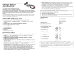
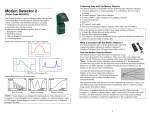
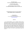
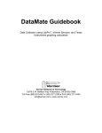
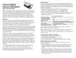
Vernier Rotary Motion Sensor (Order Code RMV-BTD) The sensor clip can be inserted into the sensor body or the end of the rotating shaft. A sensor can be inserted into the clip. This arrangement allows you to attach a sensor to the Rotary Motion Sensor. For example you could attach a Magnetic Field Sensor to the Rotary Motion Sensor and use the Rotary Motion Sensor to accurately measure the angular position of the sensor as it is rotated to determine north. The Vernier Rotary Motion Sensor is a bidirectional angle sensor designed to measure rotational or linear position, velocity and acceleration. It is used for a variety of investigations, including: Measurement of rotational inertia Verification of the conservation of angular momentum Verification of the Law of Malus Studying the motion a physical pendulum Measurement of linear position for experiments such as the inverse square law of light Measurement of linear position for diffraction patterns or interference patterns The thumb screw can be threaded into the back of the sensor allowing the Rotary Motion Sensor to be attached to a ring stand. What is included with the Rotary Motion Sensor? The Vernier Rotary Motion Sensor product includes Rotary Motion Sensor Thumb screw 3-step pulley and mounting screw O-ring Sensor clip The sensor also has a set of accessory mounting holes which allow it to connect to existing accessories. Configuring the Rotary Motion Sensor The 3-step pulley can be mounted on the rotating shaft in either of two orientations: with the wide side of the pulley near the sensor body, or with the narrow side of the pulley near the sensor body. The easiest way to insert the 3-step pulley on the Rotary Motion Sensor shaft is hold the shaft to prevent rotation as you turn the pulley to align the key to the slot. The O-ring can be slipped over the outer pulley to increase friction when the pulley is in contact with a surface. 2 Collecting Data with the Vernier Rotary Motion Sensor Specifications This sensor can be used with the following interfaces to collect data. Vernier LabQuest® 2 or original LabQuest® as a standalone device or with a computer Vernier LabQuest® Mini with a computer Vernier LabPro® with a computer or TI graphing calculator Vernier SensorDAQ® CBL 2TM TI-Nspire™ Lab Cradle Here is the general procedure to follow when using the Rotary Motion Sensor: 1. Connect the sensor to the interface. 2. Start the data-collection software. 3. Only LabQuest App 1.1 or newer or Logger Pro 3.6.1 or newer will identify the Rotary Motion Sensor and load a default data-collection setup. You are now ready to collect data. (Note: All other combinations of equipment require you to manually set up the sensor or load an experiment file.) Resolution 1 or 0.25 1 Optical Encoder Bidirectional, quadrature encoder, 360 cycle per revolution Maximum Speed 30 rev/s at 1 resolution 7.5 rev/s at 0.25 resolution 3-step Pulley 10 mm, 29 mm and 48 mm groove diameter Data-Collection Software This sensor can be used with an interface and the following data-collection software. Logger Pro This computer program is used with LabQuest 2, LabQuest, LabQuest Mini, and LabPro. LabQuest App This program is used when LabQuest 2 or LabQuest is used as a standalone device. VSTApp This calculator application for the TI-83 Plus and TI-84 Plus contains a program called DaRotary which supports the Rotary Motion Sensor with CBL 2 and LabPro. The app can be downloaded from www.vernier.com/vst-apps and then transferred to the calculator. See www.vernier.com/vst-apps for more information on the App and Program Transfer Guidebook. DataQuest™ Software for TI-Nspire™ This calculator application for the TINspire can be used with the TI-Nspire Lab Cradle. LabVIEW National Instruments LabVIEW™ software is a graphical programming language sold by National Instruments. It is used with SensorDAQ and can be used with a number of other Vernier interfaces. See www.vernier.com/labview for more information. NOTE: Vernier products are designed for educational use. Our products are not designed nor recommended for any industrial, medical, or commercial process such as life support, patient diagnosis, control of a manufacturing process, or industrial testing of any kind. How the Rotary Motion Sensor Works The Rotary Motion Sensor uses a quadrature optical (incremental type) encoder to measure the amount and direction of rotation. The encoder, which is attached to the rotating sensor shaft, consists of a coded pattern of opaque and transparent sectors. The quadrature encoder produces two pulse output patterns 90 apart in phase. The position of the shaft is determined by counting the pulses. The phase relationship between the output signals determines the direction of rotation. Example Experiments The following examples show various ways to use the Rotary Motion Sensor. Some of these examples use accessory products described below. Atwood’s Machine Attach the 3-step pulley to the rotating shaft. Use the thumb screw to attach the Rotary Motion Sensor to a ring stand. Attach each end of the string to a mass and run the string over the pulley. Use the Rotary Motion Sensor to determine the acceleration of the system. 1 High resolution mode is also known as X4 mode. When active, the sensor has a 0.25 degree resolution and a limited maximum measurable rotational velocity. 3 4 Inverse Square Law of Light Attach the 3-step pulley to the Rotary Motion Sensor. Slip the O-ring over the largest step on the pulley. Attach the sensor clip to the Rotary Motion Sensor. Attach a Light Sensor to the clip. Place the Rotary Motion Sensor on the table top with the Light Sensor pointed at a light source and the O-ring in contact with the table. As you move the Rotary Motion Sensor toward and away from the light source, you can collect light level data as a function of distance. Moment of Inertia of a Disk (requires Rotational Motion Accessory Kit, see Accessories section) Attach an Ultra Pulley to the Rotary Motion Sensor. Attach the 3-step pulley to the rotating shaft. Attach the disk to the 3-step pulley. Attach a string to the underside of the hub. Attach the Ultra Pulley to the Rotary Motion Sensor using the Ultra Pulley Swivel Mount. Run the string over the Ultra Pulley and attach a weight to the end of the string. Use the weight to apply a torque to the system while the Rotary Motion Sensor measures the angular acceleration. Conservation of Angular Momentum (requires Rotational Motion Accessory Kit, see Accessories section) Attach disk to the 3-step pulley. Give the disk a spin. While the system is rotating, drop a second disk onto the first disk. Observe the change in the angular velocity before and after the mass is added to the system. Motion of a Physical Pendulum (requires Rotational Motion Accessory Kit, see Accessories section) Attach the 3-step pulley to the Rotary Motion Sensor with the small step next to the sensor body. Attach the center of the rod with two masses to the pulley. Position the masses so they are not symmetric. Position the sensor so the face of the pulley is vertical. Start the pendulum swinging, and determine the angular acceleration as a function of the angle. Moment of Inertia of Point Masses (requires Rotational Motion Accessory Kit, see Accessories section) Use the same set up as described in the previous section. This time attach a rod with two masses to the 3-step pulley. Use the weight to apply a torque to the system while the Rotary Motion Sensor measures the angular acceleration. 5 6 Accessories Rotational Motion Accessory Kit (AK-RMV) This kit provides a variety of items that add to the versatility of the Rotary Motion Sensor. The items include the following. Used with the inverted 3-step pulley to observe Large aluminum disks (2) conservation of angular momentum. Used with the hub to measure rotational inertia of a Steel disk with central hole cylinder Used with the disk described above to measure Hub rotational inertia of a cylinder. Used with the masses to measure rotational inertia Hollow rod or to make a pendulum Masses (2) with locking Used with the hollow rod to measure rotational screws inertia. Spindle/screw Used to hold disks in place Ultra Pulley Use to apply a torque to the 3-step pulley Allows the Ultra Pulley to be connected to the Ultra Pulley Swivel Mount Rotary Motion Sensor Rotary Motion Motor Kit (MK-RMV) This kit includes a small 3–12 V electric motor, pulley, rubber band belt, motor clip and mounting screw. The motor can be attached to the Rotary Motion Sensor, which can be used to record the motion of the motor shaft. The motor can be used as a tachometer, generator, etc. You can also perform experiments that investigate motor efficiency in different conditions. Warranty Vernier warrants this product to be free from defects in materials and workmanship for a period of five years from the date of shipment to the customer. This warranty does not cover damage to the product caused by abuse or improper use. Items included in the Rotational Motion Accessories Kit Vernier Software & Technology 13979 S.W. Millikan Way Beaverton, OR 97005-2886 Toll Free (888) 837-6437 (503) 277-2299 FAX (503) 277-2440 [email protected] www.vernier.com Rev. 10/24/2014 Logger Pro, Logger Lite, Vernier LabQuest 2, Vernier LabQuest, Vernier LabQuest Mini, Vernier LabPro, and other marks shown are our trademarks or registered trademarks in the United States. TI-Nspire is a trademark of Texas Instruments. All other marks not owned by us that appear herein are the property of their respective owners, who may or may not be affiliated with, connected to, or sponsored by us. Printed on recycled paper. 7 8