1
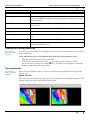
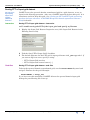
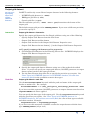
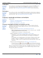
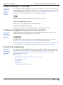
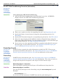
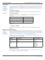
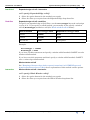
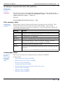
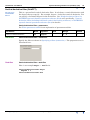
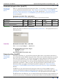
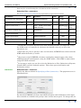
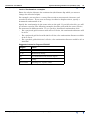
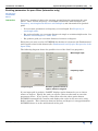
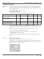
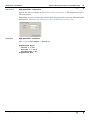
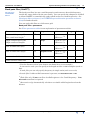
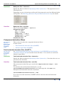
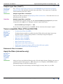
INTREPID User Manual
Library | Help | Top
Spectral domain grid filters tool (GridFFT) (T40)
1
| Back |
Spectral domain grid filters tool (GridFFT) (T40)
Top
This chapter refers to the current Spectral Domain Grid Filters tool (GridFFT).1
You can use the INTREPID GridFFT to enhance a grid dataset by:
•
Enhancing features so that you can analyse them to better effect,
•
Correcting the measured position of features,
•
Removing irrelevant features, patterns or 'noise' in the grid.
•
Transform the signal using the principles of physics.
The INTREPID GridFFT process has three basic steps:
1
Prepare and transform your grid dataset from the spatial domain to the spectral
domain, using a Fast Fourier Transform (FFT).
2
Apply a range of geophysical, directional, noise removal and wavenumber
dependent filters. It can apply filters singly or combine as many as you wish.
3
Transform your grid dataset back to the spatial domain, using a Reverse Fast
Fourier Transform (ReverseFFT).
In this chapter:
•
How to use this chapter
•
Using the GridFFT tool (interactive only)
•
The GridFFT window
•
Specifying Input and Output (Filtered) Datasets
•
Frequency, wavelength and distance unit multiples
•
Fundamental and Nyquist Frequencies of the Input Grid
•
Pre FFT Grid Conditioning
•
Post-filter transformation options
•
GridFFT filters overview
•
Combinable filters
•
Compound derivative filters
•
Tensor compatible filters (FTG and FALCON)
•
Apply the filters (interactive only)
•
Exit from GridFFT (interactive only)
•
Help (interactive only)
•
Task specification (job) files in GridFFT
1.We also support the previous tool, Old GridFFT. See Old spectral domain grid filters
(OldGridFFT) (T38) for details.
Library | Help | Top
© 2012 Intrepid Geophysics
| Back |
INTREPID User Manual
Library | Help | Top
Spectral domain grid filters tool (GridFFT) (T40)
2
| Back |
How to use this chapter
Parent topic:
Spectral
domain grid
filters tool
(GridFFT)
(T40)
In this section:
•
Chapter overview
•
Finding out more about spectral domain operations
•
The GridFFT Wizard
Chapter overview
Parent topic:
How to use this
chapter
This chapter describes the operation of the GridFFT tool. You can use the GridFFT
both interactively and in INTREPID batch processing mode, using INTREPID task
specification (.job) files.
Where needed in this chapter, there are separate Interactive and Task files sections.
Some sections are marked Interactive only or Task files only.
You can find out how to use the tool and also get background information as follows:
•
For instructions on using the tool interactively see Using the GridFFT tool
(interactive only).
•
For details about task specification (.job) files, see Task specification (job) files in
GridFFT
•
For instructions on using the tool in batch mode, see Using task specification files.
•
For relevant information in other chapters, see Finding out more about spectral
domain operations and The GridFFT Wizard.
Finding out more about spectral domain operations
Parent topic:
How to use this
chapter
This chapter briefly describes the GridFFT tool’s operations.
INTREPID has a number of tools that perform spectral domain operations and use
spectral domain filters. We have created a common reference chapter, which has
detailed explanation of INTREPID spectral domain operations. It includes an
explanation of pre-processing and post-processing, as well as details of the available
filters.
NOTE: this tool now supports Full Tensor Gradient (FTG) and FALCON Partial
Tensor Gradient grid operations (Curvature Gradients).
This takes the form of some Low, Band & High pass operations and Tensor
Integration.
A Full Tensor Complex grid is created to support the FFT operations in this case.
See INTREPID spectral domain operations reference (R14) for full details.
The GridFFT Wizard
Parent topic:
How to use this
chapter
The GridFFT Wizard uses your answers to a set of questions to automatically
generate a GridFFT task file. After generating the file, the GridFFT Wizard executes
it in batch processing mode.
See Spectral domain grid filters (GridFFT) wizard (T39) for further information.
Library | Help | Top
© 2012 Intrepid Geophysics
| Back |
INTREPID User Manual
Library | Help | Top
Spectral domain grid filters tool (GridFFT) (T40)
3
| Back |
Using the GridFFT tool (interactive only)
Parent topic:
Spectral
domain grid
filters tool
(GridFFT)
(T40)
Interactive
>> To use GridFFT with the INTREPID graphic user interface
1
Choose GridFFT from the Filter menu of the Project Manager or use the command
gfilt.exe. INTREPID displays the GridFFT window.
2
If you have a task specification file, load it using Load Options from the File
menu. (See Specifying Input and Output (Filtered) Datasets below for detailed
instructions.) If all of the specifications are correct in this file, go to step 8. If you
wish to modify any settings, carry out the following steps as required.
3
Specify the input grid dataset to be filtered. Use one of the methods in Specifying
Input and Output (Filtered) Datasets.
4
If the input data is in the spatial domain (not already FFT-transformed):
5
Library | Help | Top
•
If you want to save a copy of the FFT-transformed grid for future use to save
processing time, specify this and the dataset name for this grid. See Saving
FFT of input grid dataset below for detailed instructions.
•
Use Pre FFT Grid Conditioning properties to specify the parameters for the
transformation (See Pre FFT Grid Conditioning for detailed instructions.)
Select the filters to be used in the process from the Available filters list. For each
filter, set its parameters. See GridFFT filters overview and INTREPID spectral
domain operations reference (R14).
© 2012 Intrepid Geophysics
| Back |
INTREPID User Manual
Library | Help | Top
Spectral domain grid filters tool (GridFFT) (T40)
4
| Back |
6
Use Post-FFT Grid Restoration properties to set parameters for the post-filter
reverse FFT transformation (See Post-filter transformation options below for
detailed instructions.)
7
Specify the output grid dataset for the results of the filtering. Use one of the
methods in Specifying Input and Output (Filtered) Datasets.
8
Choose Apply. INTREPID performs the filter process, saves the output dataset
and displays the results graphically in the Data display tabs.
9
Examine the graphical display of the filter process and results in the Data display
tabs. (See Data display tabs below for information).
10 If you wish to record the specifications for this process in a .job file, so that you
can perform a similar task later, use Save Options from the File menu. (See
Specifying Input and Output (Filtered) Datasets below for detailed instructions.)
11 If you wish to repeat the process, repeat steps 2–10, varying the parameters and
data files as required.
12 To exit from GridFFT, choose Quit from the File menu.
___
After using GridFFT you can carry out a more detailed inspection of the filtered grid
using an INTREPID visualisation tool. See Visualisation (T26)
You can choose options from the Help menu (See Help (interactive only) below).
You can execute GridFFT as a batch task using a task specification (.job) file that
you have previously prepared. See Using task specification files below for details.
Library | Help | Top
© 2012 Intrepid Geophysics
| Back |
INTREPID User Manual
Library | Help | Top
Spectral domain grid filters tool (GridFFT) (T40)
5
| Back |
The GridFFT window
Parent topic:
Spectral
domain grid
filters tool
(GridFFT)
(T40)
In this section:
•
Elements of the GridFFT window
•
Changing the display panel size
•
Data display tabs
Elements of the GridFFT window
Parent topic:
How to use this
chapter
Here is a diagram of the GridFFT window.
Fundamental and Nyquist frequencies or wavelengths
Process step properties
Title bar
Menu bar
Toolbar
Available filters list
Add & Remove buttons
Filtering process list
Panel size adjustment
Data display tabs
Data display area
Apply button
The following table describes the screen elements.
Element
Purpose
Title bar
Shows the name of the tool and the input grid dataset.
Menu bar
Enables you to specify input datasets, output datesets, job files and
to view on-line help.
Toolbar
Buttons for specifying input and output datasets as well as units
and multiples for the filter parameters.
Fundamental and Nyquist
frequencies or wavelengths
Fundamental and Nyquist frequencies for the input dataset. This
also shows the units and multiples you have selected and whether
you have selected frequency or wavelength mode
Library | Help | Top
© 2012 Intrepid Geophysics
| Back |
INTREPID User Manual
Library | Help | Top
Spectral domain grid filters tool (GridFFT) (T40)
6
| Back |
Element
Purpose
Available filters list
A list of filters available. You can select filters from this list.
Filtering process list
Sequence of steps in the filtering process. When you click an item in
the list, INTREPID displays the step’s properties in the Process step
properties area.
Add & Remove buttons
Use these buttons to add and remove filters from the Filtering
process list
Process step properties
Properties of the currently selected Filtering process step
Apply button
Click this button to run the filtering process
Data display tabs
Use these to select the data display you require. See Data display
tabs.
Data display area
Graphic display of data from the filtering process
Panel size adjustment
Use this to change the relative size of the data display area and the
lists and properties area
Changing the display panel size
Parent topic:
How to use this
chapter
Use the panel size control to change the relative size of the data display area and the
task control area.
>> To adjust the size of the data display and task specification areas
•
Drag the panel size control up or down OR
•
Click the up and down arrow icons
to make the data display or task
specifcation area occupy the whole wondow. Click the icons again to restore the
display so that both areas are visible.
Data display tabs
Parent topic:
How to use this
chapter
After you have applied a filter, you can view the results graphically using the data
display tabs.
Spatial view tab
This tab shows the input and output grid in pseudocolour in the spatial domain. The
display shows the input grid and the final result.
Library | Help | Top
© 2012 Intrepid Geophysics
| Back |
INTREPID User Manual
Library | Help | Top
Spectral domain grid filters tool (GridFFT) (T40)
7
| Back |
Spectral Map View tab
This tab shows graphically the spectral amplitude and phase maps of:
•
The input dataset
•
The filter applied
•
The output dataset
Radial Power Spectrum tab
This tab show the radially averaged power spectrum graphs of the input dataset
(blue) and the output dataset (red). See "Power spectrum graphs" in INTREPID
spectral domain operations reference (R14) for more information about these graphs.
Library | Help | Top
© 2012 Intrepid Geophysics
| Back |
INTREPID User Manual
Library | Help | Top
Spectral domain grid filters tool (GridFFT) (T40)
8
| Back |
Specifying Input and Output (Filtered) Datasets
Parent topic:
Spectral
domain grid
filters tool
(GridFFT)
(T40)
In this section:
•
Specifying input and output (filtered) datasets overview
•
Input grid dataset
•
Expanded and filled input grid dataset
•
Expanded input grid after edge damping
•
Saving FFT of input grid dataset
•
Output grid dataset
•
Load options
•
Save options
Specifying input and output (filtered) datasets overview
Parent topic:
Specifying
Input and
Output
(Filtered)
Datasets
The GridFFT process involves an input grid dataset, an output grid dataset and a
number of intermediate datasets.
When using GridFFT, specify the following:
•
Input grid dataset (and band number if not band 0)
•
(Optional) Detrended, expanded and filled input dataset
•
(Optional) Rolled-off input dataset
•
(Optional) FFT-tranformed input dataset
•
Output dataset (and precision if not IEEE4ByteReal)
Filenames can have paths attached. Paths can be relative or absolute.
The following diagram show the ways of specifying input and output datasets in
interactive mode.
Input dataset
properties
File menu
Output dataset
properties
Input and output
dataset toolbar
buttons
If you choose a toolbar button, menu option or browse [...] button, INTREPID displays
an Open or Save As dialog box. Use the directory and file selector to locate the file
you require. (See "Specifying input and output files" in Introduction to INTREPID
(R02) for information about specifying files).
You can also type the path and filename of the dataset in the text boxes in the
Properties area.
Library | Help | Top
© 2012 Intrepid Geophysics
| Back |
INTREPID User Manual
Library | Help | Top
Spectral domain grid filters tool (GridFFT) (T40)
9
| Back |
Input grid dataset
Parent topic:
Specifying
Input and
Output
(Filtered)
Datasets
GridFFT can directly input and process the following grid dataset types:
•
INTREPID/ERMapper grid files (*.ers)
•
Geosoft grid files (*.grd)
You can specify already FFT-transformed datasets as input. GridFFT automatically
detects that they are transformed and skips the pre-processing steps.
You can specify an INTREPID grid dataset as if it is an ERMapper grid file. Specify
the .ers file.
The default band for filtering is 1. If you are filtering a single band grid or want to
filter the first band of a multiband grid, you don’t have to specify the grid band.
Interactive
Input grid dataset—interactive
You can specify the input grid dataset interactively using:
•
Open Input Grid Dataset from the File menu
•
Input Grid Dataset toolbar button
•
Input Grid text box in the Input Grid Dataset Properties area (type in the
filename and path).
•
Input Grid Dataset browse button [...] in the Input Grid Dataset Properties area
>> To specify the input grid dataset
1
Click Input Grid Dataset in the Filtering Process list. INTREPID displays the
Input Grid Dataset properties.
2
Specify the input grid dataset filename using one of the methods described above.
3
Specify the input grid band number for filtering using the Input Band No spin
box.
4
Specify the distance units for unit labels in the display (See Grid file distance
units).
If you load a tensor grid, GridFFT configures itself to show the available filters.
Task files
Input grid dataset—task files
In the task file, use the InputGridName keyword with the path and name of the
input grid header or marker file. For example:
InputGridName = C:\dfa_jobs\input_grids\dargo3061.ers
There is no default value for InputGridName. You must include this statement.
Use the Band keyword to specify the band to be filtered. For example:
Band = 3
Library | Help | Top
© 2012 Intrepid Geophysics
| Back |
INTREPID User Manual
Library | Help | Top
Spectral domain grid filters tool (GridFFT) (T40)
10
| Back |
Grid file distance units
This drop-down list in the Input Dataset Properties specifies unit labels for the
display. It does not affect any data or the value of any data display.
For projected grids, the default unit is metres. GridFFT labels distances as m and
frequencies as cycles/m. You can also choose feet and ‘distance units’
For geodetic grids, the only distance unit available is degrees º. GridFFT labels
distances as º and frequencies as cycles/º.
Expanded and filled input grid dataset
Parent topic:
Specifying
Input and
Output
(Filtered)
Datasets
During the pre-FFT processing, GrifFFT saves a copy of the input grid after it has
detrended, expanded and filled the new cells. After use, GridFFT normally deletes
this grid. It is sometimes useful to keep this grid. See "Saving pre-FFT and FFT grid
processing products for later reference" in INTREPID spectral domain operations
reference (R14) for details.
Interactive
Expanded and filled input grid dataset—interactive
>> To specify saving the expanded and filled input grid dataset:
Task files
1
Click Pre FFT Grid Conditioning in the Filtering Process list. INTREPID
displays the Pre FFT Grid Conditioning properties.
2
Click Advanced. INTREPID displays the Advanced Pre FFT Grid Conditioning
dialog box.
3
Tick Save Expanded Grid File
4
Use the Save Expanded Grid File text box or browse button[...] to specify the
name of the expanded input grid dataset.
Expanded and filled input grid dataset—task files
To keep the expanded and filled grid, use the ExpandedGridName keyword and
assign a filename for the grid. Example:
ExpandedGridName = dargo_exp
If you leave out this statement, GridFFT deletes the grid during the post-filtering file
clean-up.
Library | Help | Top
© 2012 Intrepid Geophysics
| Back |
INTREPID User Manual
Library | Help | Top
Spectral domain grid filters tool (GridFFT) (T40)
11
| Back |
Expanded input grid after edge damping
Parent topic:
Specifying
Input and
Output
(Filtered)
Datasets
During the pre-FFT processing, GrifFFT saves a copy of the input grid after it has
coompleted the edge roll-off process. After use, GridFFT normally deletes this grid.
It is sometimes useful to keep this grid. See "Saving pre-FFT and FFT grid
processing products for later reference" in INTREPID spectral domain operations
reference (R14) for details.
Interactive
Expanded input grid after edge damping—interactive
>> To specify saving the expanded and edge rolled off input grid dataset:
Task files
1
Click Pre FFT Grid Conditioning in the Filtering Process list. INTREPID
displays the Pre FFT Grid Conditioning properties.
2
Click Advanced. INTREPID displays the Advanced Pre FFT Grid Conditioning
dialog box.
3
Tick Save Edge Rolled Off Grid File.
4
Use the Save Edge Rolled Off Grid File text box or browse button[...] to specify the
name of the expanded and edge rolled off input grid dataset.
Expanded input grid after edge damping—task files
To keep a copy of the grid after the edge roll-off process, use the WindowedGridName
keyword and assign a filename for the grid. Example:
WindowedGridName = dargo_wind
If you leave out this statement, GridFFT deletes the grid during the post-filtering file
clean-up.
Library | Help | Top
© 2012 Intrepid Geophysics
| Back |
INTREPID User Manual
Library | Help | Top
Spectral domain grid filters tool (GridFFT) (T40)
12
| Back |
Saving FFT of input grid dataset
Parent topic:
Specifying
Input and
Output
(Filtered)
Datasets
GridFFT saves the spectral domain–transformed grid in a grid datsaset, to use as
input for the filtering operation. After use, GridFFT normally deletes this grid. It is
sometimes useful to keep this grid. See "Saving pre-FFT and FFT grid processing
products for later reference" in INTREPID spectral domain operations reference
(R14) for details.
Interactive
Saving FFT of input grid dataset—interactive
>> To enable saving the FFT of the input grid and specify a filename
Task files
1
Display the Input Grid Dataset Properties area (click Input Grid Dataset in the
Filtering Process list).
2
Tick the Save FFT of Input Grid? checkbox.
3
The default filename for the FFT grid is input grid name with _FFT appended. If
you want a different name, specify it using:
•
FFT of Input Grid text box
•
FFT of Input Grid browse button [...]
Saving FFT of input grid dataset—task files
To keep the spectral domain–transformed grid, use the FftGridName keyword and
assign a filename for the grid. Example:
FftGridName = dargo_fft
If you leave out this statement, GridFFT deletes the spectral domain input grid
during the post-filtering file clean-up.
Library | Help | Top
© 2012 Intrepid Geophysics
| Back |
INTREPID User Manual
Library | Help | Top
Spectral domain grid filters tool (GridFFT) (T40)
13
| Back |
Output grid dataset
Parent topic:
Specifying
Input and
Output
(Filtered)
Datasets
GridFFT can directly create filtered output datasets in the following formats:
•
INTREPID grid datasets (*..GRID)
•
ERMapper grid files (*.ers)
•
Geosoft grid files (*.grd)
The file extension you use (..GRID, .ers or .grd) determines the format of the
output grid.
The default output grid precision IEEE4ByteReal. If you want a different precision,
you need to specify it.
Interactive
Output grid dataset—interactive
Specify the output grid dataset for the filtered grid data using one of the following:
•
Specify Output Grid Dataset from the File menu
•
Output Grid Dataset toolbar button
•
Output Grid text box in the Output Grid Dataset Properties area.
•
Output Grid Dataset browse button [...] in the Output Grid Dataset Properties
>> To specify output grid dataset and its properties
Task files
1
Click Output Grid Dataset in the Filtering Process list. INTREPID displays the
Output Grid Dataset Properties area.
2
Specify the output grid dataset filename using one of the methods described
above. If you do not specify an output grid dataset, GridFFT generates an output
dataset name based on the input grid name.
3
Use the Data Format drop-down list to specify the precision you require. See
"Data Types in INTREPID datasets" in INTREPID database, file and data
structures (R05) for the available numeric data types.
Output grid dataset—task files
Use the FilteredGridName keyword with the path and name of the output grid
header or marker file. For example:
FilteredGridName = C:\dfa_jobs\gfilt_test\dargo_HorDerivN..GRID
If you leave out this statement, GridFFT generates an output dataset name based on
InputGridName and filters applied.
You can specify the data type of the output grid. Use the OutputPrecision keyword
with the precision you require. See "Data Types in INTREPID datasets" in
INTREPID database, file and data structures (R05) for a list of data types available
and their notation. Example:
OutputPrecision = Signed32BitInteger
If you leave out this statement, GridFFT creates the output dataset with the data
type IEEE4ByteReal (4-byte real)
Library | Help | Top
© 2012 Intrepid Geophysics
| Back |
INTREPID User Manual
Library | Help | Top
Spectral domain grid filters tool (GridFFT) (T40)
14
| Back |
Load options
Parent topic:
Specifying
Input and
Output
(Filtered)
Datasets
If you wish to use an existing task specification file to specify the GridFFT process,
use Load Options from the File menu. INTREPID uses the file to set all of the
parameters. (See Task specification (job) files in GridFFT for more information).
Save options
Parent topic:
Specifying
Input and
Output
(Filtered)
Datasets
If you wish to save the current GridFFT file specifications and parameter settings as
a task specification file, use Save Options from the File menu to specify the filename
and save the file. (See Task specification (job) files in GridFFT
Frequency, wavelength and distance unit multiples
Parent topic:
Spectral
domain grid
filters tool
(GridFFT)
(T40)
In this section:
•
Frequency, wavelength and distance unit multiples overview
•
Frequency or wavelength units
•
Distance unit multiples x 1 and x 1000
Frequency, wavelength and distance unit multiples overview
Parent topic:
Specifying
Input and
Output
(Filtered)
Datasets
GridFFT accepts parameters and displays data in a variety of modes and units
depending on the dataset and the options you select. You can select from the the
following sets of options:
•
•
Distance units (seeGrid file distance units in Input grid dataset)
•
With a projected grid you can work in metres, feet or ‘distance units’. GridFFT
labels its display with the unit you select.
•
GridFFT always uses degrees º with geodetic grids.
Distance multiples (see Distance unit multiples x 1 and x 1000)
•
Using the [ x 1 ] or [ x 1000 ] multiple button with a projected grid you can
specify parameters in your selected distance unit singly or in multiples of
1000.
For example, you can specify metres as the distance unit but use the x 1000
multiple. In this case, GridFFT accepts parameters and displays data in
kilometres. (Note: It does not change the unit of the output data—this is still
in metres)
•
Frequency and wavelength modes (see Frequency or wavelength units)
•
Using the Frequency
and Wavelength
buttons in the spectral domain,
you can specify parameters and view results using frequencies or wavelengths
When you switch between multiples and modes, GridFFT automatically converts all
parameter settings. If you switch distance units, GridFFT changes labels, but this
does not affect values or calculations.
Library | Help | Top
© 2012 Intrepid Geophysics
| Back |
INTREPID User Manual
Library | Help | Top
Spectral domain grid filters tool (GridFFT) (T40)
15
| Back |
These settings affect the following parameters and displays:
•
Fundamental and Nyquist (see Fundamental and Nyquist Frequencies of the
Input Grid)
•
Pass filter parameters (see Entering parameters for pass filters (interactive only))
•
Continuation filter parameters (see Continuation filter (GridFFT))
The following table summarises the results of distance unit, multiple and mode
selections for projected and geodetic grids.
Projection, selected multiple and distance unit
Domain
and mode
Spatial
Spectral (frequency)
Spectral (wavelength)
Projected [ x 1 ]
Projected [ x 1000 ]
Geodetic
m
ft
du
m
ft
du
º
m
ft
du
km
kft
kdu
º
cy/m
cy/ft
cy/du
cy/km
cy/kft
cy/kdu
cy/º
m
ft
du
km
kft
kdu
º
Frequency or wavelength units
Parent topic:
Specifying
Input and
Output
(Filtered)
Datasets
You can specify and view spectral domain values as frequencies or wavelength. Use
the Frequency and Wavelength buttons on the Toolbar to select the system you
require. See Frequency, wavelength and distance unit multiples for more
information about units display and input.
>> To use frequency values in the spectral domain
Click the Frequency
button.
>> To use wavelength values in the spectral domain
Click the Wavelength
Library | Help | Top
button.
© 2012 Intrepid Geophysics
| Back |
INTREPID User Manual
Library | Help | Top
Spectral domain grid filters tool (GridFFT) (T40)
16
| Back |
Distance unit multiples x 1 and x 1000
Parent topic:
Specifying
Input and
Output
(Filtered)
Datasets
You can specify and view distance units as single units (m, ft, distance units dU) or
x 1000 multiples (km, kft, kdU). Use the [ x 1 ] and [ x 1000 ] buttons on the Toolbar
to select the multiple you require. See Frequency, wavelength and distance unit
multiples for more information about units display and input.
These buttons are disabled when your input grid is geodetic.
>> To use single distance units
Click [ x 1 ] to use single distance units (m, ft, dU).
>> To use x 1000 distance units
Click [ x 1000 ] to use x 1000 multiple distance units (km, kft, kdU).
Fundamental and Nyquist Frequencies of the Input Grid
Parent topic:
Spectral
domain grid
filters tool
(GridFFT)
(T40)
GridFFT automatically displays the fundamental and Nyquist frequencies of the
input grid dataset at the right end of the Toolbar.
It displays the values using the units and multiple you have selected. See for
Frequency, wavelength and distance unit multiples for instructions.
For information about the fundamental and Nyquist frequencies, see "The spatial and
spectral domains" in INTREPID spectral domain operations reference (R14).
Pre FFT Grid Conditioning
Parent topic:
Spectral
domain grid
filters tool
(GridFFT)
(T40)
Library | Help | Top
You can specify how GridFFT prepares the input grid for FFT. This section briefly
describes the steps in the process and the parameters. For detailed discussion, see
"Preparation of data for spectral transform" in INTREPID spectral domain
operations reference (R14).
In this section:
•
Pre-FFT Grid Conditioning Overview (Interactive)
•
Expanding the grid
•
Detrending
•
Fill method
•
Edge damping rolloff options
© 2012 Intrepid Geophysics
| Back |
INTREPID User Manual
Library | Help | Top
Spectral domain grid filters tool (GridFFT) (T40)
17
| Back |
Pre-FFT Grid Conditioning Overview (Interactive)
Parent topic:
Frequency,
wavelength
and distance
unit multiples
Interactive
>> To specify Pre FFT Grid Conditioning
1
Click Pre FFT Grid Conditioning in the Filtering Process list. INTREPID
displays the The Pre FFT Grid Conditioning properties.
2
There are no options to select for expanding the grid. See Expanding the grid.
3
Specify the Degree of trend removal using the corresponding spin box. See
Detrending.
4
Specify the Fill method using the corresponding drop-down list. See Fill method.
5
Select the edge damping method (Whole window or Expanded edge) using the
Grid edge rolloff option buttons. For the method you choose, select the filter type
from its drop-down list. See Edge damping rolloff options.
6
If you want to save the expanded and filled or expanded and rolled off version of
the input grid, use the Advanced button. See Expanded and filled input grid
dataset and Expanded input grid after edge damping.
Expanding the grid
Parent topic:
Frequency,
wavelength
and distance
unit multiples
GridFFT always expands the grid to dimensions suitable for FFT. There are no
parameters attached to this process. See "Expanding the data area" in INTREPID
spectral domain operations reference (R14) for an explanation of this stage.
Detrending
Parent topic:
Frequency,
wavelength
and distance
unit multiples
GridFFT always detrends the grid. See "Detrending data values" in INTREPID
spectral domain operations reference (R14) for information. The value you select or
assign to the keyword corresponds to the degrees in this reference topic.
Interactive
Detrending degree—interactive
Select the degree required from the Degree of Trend Removal drop-down list.
Task files
Detrending degree—task files
You can specify the degree of the detrending using the DetrendDegree keyword.
Example:
DetrendDegree = 1
If you leave out this statement, GridFFT detrends the grid with degree 0.
Library | Help | Top
© 2012 Intrepid Geophysics
| Back |
INTREPID User Manual
Library | Help | Top
Spectral domain grid filters tool (GridFFT) (T40)
18
| Back |
Fill method
Parent topic:
Frequency,
wavelength
and distance
unit multiples
After expanding the grid, GridFFT assigns values to the new cells in the grid using an
extrapolation process. You can choose one of two available methods See "Estimating
values for data gap cells" in INTREPID spectral domain operations reference (R14)
for details.
Interactive
Fill method—interactive
Select Arthur or MEM (Maximum Entropy) from the Fill Method drop-down list.
Task files
Fill method—task files
To select a fill method, use the FillType keyword. The following methods are
available:
Fill method
Value to assign
Linear interpolation (Arthur)
ARTHUR
Maximum entropy
MEM
Source fill
SOURCE_GRID
Example:
FillType = ARTHUR
If you leave out this statement, GridFFT uses the linear interpolation (Arthur)
method.
Edge damping rolloff options
Parent topic:
Frequency,
wavelength
and distance
unit multiples
For best results from the FFT, the edges of the grid must be set to zero, but without
sudden changes from the data within the grid. The grid data needs to ‘roll off’ to zero
at the edge. See "Damping of dataset edges before spectral transform" in INTREPID
spectral domain operations reference (R14) for details of this process.
GridFFT has two main roll-off methods, each of which has a number of filters. It is
normal to only use one of the methods.
Method
Description
Filters available
Expanded edge
roll-off
Rolloff operation only on the edges of the
grid
Cosine
Linear
Whole window
roll-off
Rolloff operation across the whole grid
Cosine bell
Hanning
Hamming
Blackman
Triangle
Expanded edge roll-off
See "Expanded edge rolloff" in INTREPID spectral domain operations reference (R14)
for an explanation of this method and its options.
Library | Help | Top
© 2012 Intrepid Geophysics
| Back |
INTREPID User Manual
Library | Help | Top
Interactive
Spectral domain grid filters tool (GridFFT) (T40)
19
| Back |
Expanded edge roll-off—interactive
>> To specify Expanded Edge rolloff
Task files
1
Select the option button for the method you require
2
Select the filter you require from the Expanded Edge drop-down list.
Expanded edge roll-off—task files
To specify an expanded edge roll-off filter, use the RolloffType keyword and assign
a value to it. If you specify a rolloff method, you normally do not specify a window
roll-off (WindowType) method as well (See Whole window roll-off below):
Roll-off method
RolloffType value
Required WindowType value
Linear
LINEAR
NONE
Cosine
COSINE
NONE
No roll-off
NONE
as required
Example:
RolloffType = LINEAR
WindowType = NONE
If you leave out this statement and specify a window rolloff method, GridFFT uses the
window rolloff method.
If you leave out this statement and don’t specify a window rolloff method, GridFFT
uses a cosine edge rolloff method.
Whole window roll-off
See "Damping of dataset edges before spectral transform" in INTREPID spectral
domain operations reference (R14) for an explanation of this method and its options.
Interactive
Whole window roll-off—interactive
>> To specify Whole Window rolloff
Library | Help | Top
1
Select the option button for the method you require
2
Select the filter you require from the Whole Window drop-down list.
© 2012 Intrepid Geophysics
| Back |
INTREPID User Manual
Library | Help | Top
Task files
Spectral domain grid filters tool (GridFFT) (T40)
20
| Back |
Whole window roll-off—task files
To specify a the whole window roll-off method, use the WindowType keyword and
assign a value to it. GrifFFT provides five window roll-off methods, as shown in the
following table. If you specify a whole window rolloff method, you normally do not
specify an expanded edge roll-off (RolloffType) method as well (See Expanded edge
roll-off above):
Window roll-off method
WindowType value
Required RolloffType value
Linear
COSINE_BELL
NONE
Cosine
HANNING
NONE
Hamming
HAMMING
NONE
Blackman
BLACKMAN
NONE
Bartlett or Triangular
TRIANGLE
NONE
No roll-off
NONE
as required
Example:
RolloffType = NONE
WindowType = BLACKMAN
If you leave out the WindowType statement, GridFFT uses an expanded edge rolloff
method.
If you leave out this statement and don’t specify an expanded edge rolloff method,
GridFFT uses a cosine expanded edge rolloff method.
Post-filter transformation options
Parent topic:
Spectral
domain grid
filters tool
(GridFFT)
(T40)
After applying the filters, GridFFT restores the filtered grid to correspond with the
input grid.
The post-filter transformation operations are as follows:
•
Apply reverse FFT to return the grid to the spatial domain.
•
Remove the expanded edge of the grid.
•
Reapply the trend (optional).
•
Restore null to cells that were originally null (optional).
See "Post-filter transformation" in INTREPID spectral domain operations reference
(R14) for details.
In this section:
Library | Help | Top
•
Post-FFT transformation options overview (Interactive)
•
Reverse FFT and removing the expanded edge
•
Reproducing the trend
•
Regenerating the data gaps
© 2012 Intrepid Geophysics
| Back |
INTREPID User Manual
Library | Help | Top
Spectral domain grid filters tool (GridFFT) (T40)
21
| Back |
Post-FFT transformation options overview (Interactive)
Parent topic:
Post-filter
transformation
options
Interactive
>> To specify Post-FFT transformation options
1
Click Post-FFT Grid Restoration in the Filtering Process list. INTREPID displays
the The Post-FFT Grid Restoration properties.
2
There are no options to select for the reverse FFT process. See Reverse FFT and
removing the expanded edge.
3
If you want to reapply the trend that you removed before the FFT, tick the
Reapply Trend on Output check box. See Reproducing the trend.
4
If you want to restore nulls that existed in the grid before the Pre-FFT process,
tick the Apply Mask on Output check box. This refers to nulls within the grid,
not in the expanded edge. See Regenerating the data gaps.
Reverse FFT and removing the expanded edge
Parent topic:
Post-filter
transformation
options
GridFFT always applies reverse FFT and removes the expanded edge of the dataset
after reverse FFT. See "Reducing the dataset" in INTREPID spectral domain
operations reference (R14) for details.
Reproducing the trend
Parent topic:
Post-filter
transformation
options
GridFFT can reapply the trend that it removed when preparing for FFT. See
"Reproducing the trend" in INTREPID spectral domain operations reference (R14) for
an explanation.
Interactive
Reproducing the trend—interactive
If you want to reapply the trend that you removed before the FFT, tick the Reapply
Trend on Output check box.
Task files
Reproducing the trend—task files
You can specify whether to reproduce the trend using the
ReApplyTrendAfterReverseFft keyword. Assign the value YES or NO (or 1 for yes,
0 for no). Example:
ReApplyTrendAfterReverseFft = YES
If you leave out this statement, GridFFT does not reapply the trend.
Library | Help | Top
© 2012 Intrepid Geophysics
| Back |
INTREPID User Manual
Library | Help | Top
Spectral domain grid filters tool (GridFFT) (T40)
22
| Back |
Regenerating the data gaps
Parent topic:
Post-filter
transformation
options
GridFFT can restore null values to cells that had this value before FFT. See
"Regenerating the data gaps" in INTREPID spectral domain operations reference
(R14) for an explanation. This only refers to cells within the grid. INTREPID always
removed the expanded edges of the grid during the post-FFT process.
Interactive
Regenerating the data gaps—interactive
If you want to restore nulls that existed in the grid before the Pre-FFT process, tick
the Apply Mask on Output check box.
Task files
Regenerating the data gaps—task files
You can specify whether to restore the null values using the
ApplyMaskAfterReverseFft keyword. Assign the value YES or NO (or 1 for yes, 0
for no). Example:
ApplyMaskAfterReverseFft = YES
If you leave out this statement, GridFFT does not restore the null values.
GridFFT filters overview
Parent topic:
Spectral
domain grid
filters tool
(GridFFT)
(T40)
GridFFT provides:
•
Filters that you can combine with other filters in the same task:
•
Continuation (downward and upward)
•
High pass, low pass and band pass
•
Vertical derivative
•
Horizontal derivative
•
Reduction (to inclination and declination, including pole and equator)
In task files these filters are within the CompositeFilter Begin – End block.
•
Compound derivative filters. You can only apply one of these in any GridFFT
operation:
•
Total horizontal derivative
•
Analytic Signal
In task files these use single statements in the Parameters Begin – End block
outside the CompositeFilter Begin – End block.
In interactive mode, if you load a tensor grid, GridFFT configures itself to show the
available filters.
In this section:
Library | Help | Top
•
Specifying a filter (interactive)
•
Specifying a combinable filter (task files)
•
Specifying a compound derivative filter (task files)
•
Filter parameter tables
© 2012 Intrepid Geophysics
| Back |
INTREPID User Manual
Library | Help | Top
Spectral domain grid filters tool (GridFFT) (T40)
23
| Back |
Specifying a filter (interactive)
Parent topic:
GridFFT filters
overview
Interactive
>> To specify a filter
1
Select a filter from the list of Available FFT Filters, and use the [>] button to add
the selected filter to the Filtering Process. You may add further filters to create a
composite filter.
2
In the Filtering Process list, select the Filter. INTREPID displays the Properties
for the filter.
3
Specify the parameters for the filter. There is no OK button. When finished,
continue to the next operation.
Specifying a combinable filter (task files)
Parent topic:
GridFFT filters
overview
Task files
The CompositeFilter Begin – End block contains one or more filter definition
Begin – End blocks.
You can only have one CompositeFilter Begin – End block in a task file.
If there are no filters in the CompositeFilter Begin – End block, you can leave it
out.
The order of filters within the CompositeFilter block is generally unimportant.
GridFFT combines the filters in a set order and then applies them to the spectral
domain–transformed data. Downward continuation has an exception to this rule
about order of filters. See Continuation filter (GridFFT) below.
Only use a particular filter definition Begin – End block once in a
CompositeFilter Begin – End block. If you repeat a particular filter, GridFFT
ignores the second occurrence. If you need to apply a filter twice, use two separate
GridFFT tasks.
Library | Help | Top
© 2012 Intrepid Geophysics
| Back |
INTREPID User Manual
Library | Help | Top
Spectral domain grid filters tool (GridFFT) (T40)
24
| Back |
Specifying a compound derivative filter (task files)
Parent topic:
GridFFT filters
overview
Task files
You can only use one of the compound derivative filters at a time. To specify one,
include its statement set to YES in the Parameters Begin – End block outside the
CompositeFilter Begin – End block.
Example
CalculateHorizontalDerivative = YES
Filter parameter tables
Parent topic:
GridFFT filters
overview
The parameters tables in this manual show the parameters for each filter. They
include parameters for both interactive mode and task files. These usually
correspond and footnotes explain any differences. The following table explains the
parts of the parameters table:
Heading
Purpose
Parameter
The INTREPID term for the parameter. This appears in the
properties area in the interactive tool.
Mode
I = Interactive, T = Task files
Keyword
(Task files only) Keyword for specifying the parameter in a task file
Unit
Unit of the parameter value (for example, metres). This may
depend on the grid data and on settings in GridFFT
Range
Acceptable range for parameter value
Default
(Task files only) INTREPID assigns this value if you leave out the
statement
In interactive mode, GridFFT shows the default value on the screen
Combinable filters
Parent topic:
Spectral
domain grid
filters tool
(GridFFT)
(T40)
Library | Help | Top
This section describes the combinable filters available in GridFFT.
In this section:
•
Vertical derivative filter (GridFFT)
•
Horizontal derivative filter (GridFFT)
•
Reduction filter (GridFFT)
•
Continuation filter (GridFFT)
•
Entering parameters for pass filters (interactive only)
•
Low pass filter (GridFFT)
•
High pass filter (GridFFT)
•
Band pass filter (GridFFT)
© 2012 Intrepid Geophysics
| Back |
INTREPID User Manual
Library | Help | Top
Spectral domain grid filters tool (GridFFT) (T40)
25
| Back |
Vertical derivative filter (GridFFT)
Parent topic:
Combinable
filters
This is a generalised vertical derivative filter. It calculates a vertical derivative with
the degree that you specify. For example, degree 1 is the first vertical derivative. You
can specify a fractional degree for the derivative. See "Single derivative filters" in
INTREPID spectral domain operations reference (R14) and, specifically, "Vertical
derivative filter (including fractional vertical derivative) (reference)" in INTREPID
spectral domain operations reference (R14) for details.
Vertical derivative filter—parameters
See Filter parameter tables for an explanation of parameters tables.
Parameter
Mode
Keyword
Order of differentiation
IT
Degree
Interactive
Unit
Range
Default
1..3
1
Vertical derivative filter—interactive
Specify the filter as shown in Specifying a filter (interactive). The properties area is
illustrated here.
Task files
Vertical derivative filter—task files
Here is an example Begin – End block:
VerticalDerivative2D Begin
Degree = 1
VerticalDerivative2D End
Library | Help | Top
© 2012 Intrepid Geophysics
| Back |
INTREPID User Manual
Library | Help | Top
Spectral domain grid filters tool (GridFFT) (T40)
26
| Back |
Horizontal derivative filter (GridFFT)
Parent topic:
Combinable
filters
This is a generalised horizontal derivative filter. It calculates a horizontal gradient
in any specified azimuth direction. See "Single derivative filters" in INTREPID
spectral domain operations reference (R14) and, specifically, "Generalised horizontal
derivative filter (reference)" in INTREPID spectral domain operations reference
(R14) for details.
Horizontal derivative filter—parameters
See Filter parameter tables for an explanation of parameters tables.
Parameter
Mode
Keyword
Unit
Range
Default
Direction
IT
Azimuth
°
0..360
0
Order of differentiation
IT
Degree
1..3
1
Interactive
Horizontal derivative filter—interactive
Specify the filter as shown in Specifying a filter (interactive). The properties area is
illustrated here.
Task files
Horizontal derivative filter—task files
Here is an example Begin – End block:
HorizontalDerivative2D Begin
Azimuth = 0.0
Degree = 1.0
HorizontalDerivative2D End
Reduction filter (GridFFT)
Parent topic:
Combinable
filters
The Reduction filter is a generalised reduction filter that can perform reduction to
any orientation of the Earth’s magnetic field. The most common reductions are to the
Pole and to the Equator. You need to specify the target magnetic field orientation you can input this manually or allow GridFFT to calculate it for you. If you are
reducing to a low latitude, you can specify the IGRF field inclination limit for the
amplitude calculation. There is also a special low latitude switch which uses a
directional filter to suppress declination parallel striping. See "Reduction filters
(reference)" in INTREPID spectral domain operations reference (R14) for further
details.
GridFFT uses the International Geomagnetic Reference Field (IGRF) model to
calculate the Earth’s magnetic field for the mean position of the input grid. See The
geomagnetic reference field in INTREPID (R15) for information about the IGRF.
For Reduction to the Equator, we recommend that the Declination angle should be set
to that of your survey to minimise any horizontal offsets in the East/West direction
Library | Help | Top
© 2012 Intrepid Geophysics
| Back |
INTREPID User Manual
Library | Help | Top
Spectral domain grid filters tool (GridFFT) (T40)
27
| Back |
that may be caused during the calculation of this correction.
Reduction filter—parameters
See Filter parameter tables for an explanation of parameters tables.
Parameter
Mode
Keyword
Unit
Range
Default
Inclination for input dat3
IT
FromInclination
°
0..90
(1)
Declination for input data3
IT
FromDeclination
°
0..360
(1)
Date of input data 2
T
Date (task file and
IGRF block)
dd/mm/yyyy
today’s
date
Elevation of input data 2
T
Elevation
m
0..
0
Target inclination 4
IT
ToInclination
°
0..90
90
Target declination 4
IT
ToDeclination
°
0..360
0
Taylor Expansion Order
IT
TaylorExpansionOrder
1..3
1
Inclination limit
IT
AmplitudeLimit
0..+/-90
+/-20
°
1
INTREPID calculates default values from middling latitude and longitude, using
the IGRF model. In task files it calculates the default values if you leave the
statements out.
2
(Task files only) If you specify a date and elevation, INTREPID uses them with the
IGRF model for better (1) values
3
(Interactive only) INTREPID calculates and displays default input values from
middling latitude and longitude, using the IGRF model. Click IGRF to adjust these
using the IGRF calculator.
4
In interactive mode you can also select the Reduction to Pole, Reduction to Equator,
Variable RTP and Low Latitude options. These have preset inclination and
declination values.
Interactive
Reduction filter—interactive
Specify the filter as shown in Specifying a filter (interactive). The properties area is
illustrated here.
By default INTREPID calculates the IGRF inclination and declination at the input
data centroid at 0 altitude using today’s date and the latest epoch. To change this, do
Library | Help | Top
© 2012 Intrepid Geophysics
| Back |
INTREPID User Manual
Library | Help | Top
Spectral domain grid filters tool (GridFFT) (T40)
28
| Back |
one of the following:
•
Enter your own values for Inclination and Declination
•
Use the IGRF Calculator (See IGRF Calculator).
•
Choose type of Reduction Equator or Pole.
•
For RTPole, the normal option is the average correction for the middle of your
grid.
•
For large grids (100km extents), the approximation of using the inclination and
declination at the grid centroid becomes inaccurate. In this case choose the
Variable RTP option and the RTP calculation will be made using a Taylor series
approximation for the gradient of the inclination and declination. In this case the
IGRF field is used and inclination and declination values cannot be entered
manually.
The user can choose the order of the Taylor series expansion (1, 2, 3). The higher
the order the more accurate the calculation
•
For geomagnetic surveys near the equator (at low magnetic field inclinations
<abs[20o]), the RTP tends to become numerically unstable particularly in the
presence of noise. The problem usually presents as declination parallel striping in
the transformed grid. Experience has found that this instability can be partially
compensated for by using a pseudo field inclination ie (20o) when computing the
amplitude component of the RTP transform while still preserving the phase. The
user can choose the inclination limit at which the transform stabilises.
The reduction filter also provides an option to apply a directional cosine roll-off to
reduce the declination parallel striping in the output. This is considered a last
resort solution and is untenable if there are real magnetic features with trends
close to the IGRF declination direction.
The directional cosine filter is always applied in the declination direction but the
user can choose the Rolloff Degree and the Azimuthal Half Width Directional
cosine filter—parameters so as to restrict the filter to a narrow corridor in the
declination direction.
Task files
Reduction filter—task files
Here is an example Begin – End block:
Reduction2D Begin
FromInclination = -7.709789858562574
FromDeclination = -20.067014031276116
ToInclination = 90.0
ToDeclination = 0.0
AmplitudeLimit = -20.0
LowLatitude = No
Variable = No
TaylorExpansionOrder = 1
UseDirCos = No
HalfWidth = 20.0
RolloffDeg = 0.5
Reduction2D End
__
Library | Help | Top
© 2012 Intrepid Geophysics
| Back |
INTREPID User Manual
Library | Help | Top
Spectral domain grid filters tool (GridFFT) (T40)
29
| Back |
IGRF Calculator
>> To use the IGRF Calculator
1
In Reduction Properties, click IGRF. INTREPID displays the IGRF Calculator.
2
Set Day, Month, Year, IGRF Epoch, Altitude, Latitude and Longitude of the input
data (see table below describing the parameters.
3
Note the calculated Field Strength, Declination and Inclination values
4
Click OK. INTREPID inserts the new calculated values into the To Declination
and To Inclination text boxes.
IGRF Calculator—parameters
Parameter
Unit
Description
Default
Day
Day (Date of survey)
Today’s Date
Month
Month (Date of survey)
Year
Year (Date of survey)
IGRF Epoch
IGRF Epoch [ie IGRF2010] - IGRF Model update
year (every 5 years); a list of current & older models
http://www.ngdc.noaa.gov/IAGA/vmod/igrf_old_models.html
Most recent epoch
for the chosen
survey date
Altitude
km
Specify the altitude of the survey
0
Latitude
Longitude
°
Specify the latitude and longitude of the input data
for the IGRF calculation
Midpoint of grid
Field Strength
nT
Output field strength from the IGRF model
Declination
°
Output declination and inclination from the IGRF
model
Inclination
Library | Help | Top
© 2012 Intrepid Geophysics
| Back |
INTREPID User Manual
Library | Help | Top
Spectral domain grid filters tool (GridFFT) (T40)
30
| Back |
Continuation filter (GridFFT)
Parent topic:
Combinable
filters
The continuation filter can calculate an upward or a downward continuation. The
filter includes optional damping for controlling the stability of downward
continuation. See "Continuation filters (reference)" in INTREPID spectral domain
operations reference (R14) for further details.
Continuation filter—parameters
See Filter parameter tables for an explanation of parameters tables.
Parameter
Mode
Direction
I
Level of Continuation1
IT
Distance
Use Damping? 2
IT
UseDamping
Median Frequency of
IT
DampingFrequency
T
DampingDegree
Rolloff
Keyword
1
Range
Default
Upward or
Downward
2
Degree of Rolloff 2
Unit
m or °
YES|NO
cyc/m or
cyc/°
NO
auto
0..15
10
In task files: Positive—upward continuation, Negative—downward continuation
Interactive: See Continuation filter—interactive
2
Downward continuation only If you do not specify Median frequency of rolloff,
INTREPID calculates a suitable value. This is based on the rate at which the
continuation is increasing high frequencies. See also Suggested values for Degree of
Rolloff
Library | Help | Top
© 2012 Intrepid Geophysics
| Back |
INTREPID User Manual
Library | Help | Top
Interactive
Spectral domain grid filters tool (GridFFT) (T40)
31
| Back |
Continuation filter—interactive
Specify the filter as shown in Specifying a filter (interactive). The properties area is
illustrated here.
Geodetic grid has choice of
input in metres or degrees
Projected grid
If your input grid is geodetic, GridFFT displays both a metres and degrees text box for
you to specify the Level of continuation. Whatever you enter in one of the text boxes,
INTREPID automatically converts and displays the equivalent in the other text box,
using Robin’s formula. This conversion between metres and degrees is an
approximation. INTREPID bases it on the mid-latitude of the grid.
Task files
Continuation filter—task files
Note: The sign of the Level of continuation parameter (Distance =) determines the
direction. If it is positive, the continuation is upward; if negative, the continuation is
downward.
Here is an example Begin – End block:
Continuation2D Begin
Distance = -100.0
# +ve upward, -ve downward
UseDamping = Yes
DampingDegree = 5.0
DampingFrequency = 0.016 # cycles/m (wavelength in metres 62.5)
Continuation2D End
___
Units for Level of Continuation
Specify the Level of continuation using the same distance units as the spatial version
of the grid. For example, if the grid is in metres, then specify Level of continuation in
metres. For geodetic grids, specify it in degrees.
(Interactive only) Remember that you can set GridFFT to display the correct units for
the grid. See Frequency, wavelength and distance unit multiples for details. This
may help avoid confusion.
Library | Help | Top
© 2012 Intrepid Geophysics
| Back |
INTREPID User Manual
Library | Help | Top
Spectral domain grid filters tool (GridFFT) (T40)
32
| Back |
Level of Continuation—examples
Enter the relative distance for continuation (the distance by which you want to
change the effective height).
For example, you may have a survey flown at 90 m mean terrain clearance and
recorded in metres. If you want to change its effective height to 60 m, specify a
downward continuation of 30.
Specify the continuation in the same units as the grid. If you fail to do this, you will
get incorrect results. The following examples describe grids with the same cell size,
but measured in different units. If we specify a downward continuation of 30:
•
For a projected grid in metres with 100 m cell size, the continuation distance will
be 30 m.
•
For a projected grid in feet with 300 ft cell size, the continuation distance would be
30 ft or 9.4 m.
•
For a geodetic grid with 0.001º cell size, the continuation distance would be 30º or
3000 km!
Suggested values for Degree of Rolloff
Library | Help | Top
Degree
Effect
2
Gradual
5–10
Moderately sharp
10
Recommended and default degree
30
Sharp
50 or more
Tending to a square cutoff
© 2012 Intrepid Geophysics
| Back |
INTREPID User Manual
Library | Help | Top
Spectral domain grid filters tool (GridFFT) (T40)
33
| Back |
Entering parameters for pass filters (interactive only)
Parent topic:
Combinable
filters
Interactive
You have a number of choices for entering spectral domain parameters the pass
filters. These include frequency, wavelength and distance unit multiples (see
Frequency, wavelength and distance unit multiples) and alternatives for geodetic
grids:
•
You can enter parameters as frequency or wavelength. See Frequency or
wavelength units.
•
For projected grids, you can enter distances in single or x 1000 multiple units. See
Distance unit multiples x 1 and x 1000.
•
For geodetic grids you can enter distances in metres or degrees.
Each time you enter a value, INTREPID checks that it is between the Fundamental
and Nyquist value for the dataset (See Fundamental and Nyquist Frequencies of the
Input Grid).
The following diagram shows the possible views of the Low Pass properties
Wavelength input
Frequency input
Projected grid
Geodetic grid has choice of
input in metres or degrees
If your input grid is geodetic, GridFFT displays option buttons for you to choose
metres or degrees. Specify the unit you require, then use that unit to enter the
parameter values. If you specify a value then select the other option button,
INTREPID automatically converts and displays the value in the new unit, using
Robin’s formula. This conversion between metres and degrees is an approximation.
INTREPID bases it on the mid-latitude of the grid.
Library | Help | Top
© 2012 Intrepid Geophysics
| Back |
INTREPID User Manual
Library | Help | Top
Spectral domain grid filters tool (GridFFT) (T40)
34
| Back |
Low pass filter (GridFFT)
Parent topic:
Combinable
filters
The low pass filter removes data with frequency above a level that you specify. You
can specify the sharpness of rolloff or allow GridFFT to automatically apply rolloff.
See "Low pass filter (reference)" in INTREPID spectral domain operations reference
(R14) for further details.
You can apply this filter to a full tensor grid.
Low pass filter—parameters
See Filter parameter tables for an explanation of parameters tables.
Parameter
Cutoff frequency OR
Cutoff wavelength
Mode
Keyword
Unit
IT
Cutoff
cyc/m or cyc/°
1
Range
Default
YES|NO
YES
OR m or ° (1)
Size of rolloff zone 1 2
IT
Automatic rolloff zone size 3
T
Auto calculate rolloff zone 4
I
Rolloff
cyc/m or cyc/°
OR m or ° (1)
AutoRolloff
1
Use the distance unit of your dataset (m shown here as an example)
In interactive mode you can specify wavelength and the x 1000 multiples (such as
km).
In task files you can only specify frequency in single units (such as m or ft)
2
In task files if present, sets AutoRolloff to NO
3
(Task files only) If YES, sets Size of rolloff region to 0.5 x Cutoff frequency.
If NO, Rolloff statement is required
4
(Interactive only) Automatically calculates a suitable rolloff region based on the
dataset
Interactive
Low pass filter—interactive
Specify the filter as shown in Specifying a filter (interactive).
The properties area is illustrated here. Depending on your tool settings and the grid,
the properties area has different labels and options. See Entering parameters for
pass filters (interactive only) for details.
Library | Help | Top
© 2012 Intrepid Geophysics
| Back |
INTREPID User Manual
Library | Help | Top
Task files
Spectral domain grid filters tool (GridFFT) (T40)
35
| Back |
Low pass filter—task files
Here is an example Begin – End block:
LowPass2D Begin
Cutoff = 0.001
Rolloff = 0.0001
AutoRolloff = 0 or 1
LowPass2D End
High pass filter (GridFFT)
Parent topic:
Combinable
filters
The high pass filter removes data with frequency below a level that you specify. You
can specify the sharpness of rolloff or allow GridFFT to automatically apply rolloff.
See "High pass filter (reference)" in INTREPID spectral domain operations reference
(R14) for further details.
You can apply this filter to a full tensor grid.
High pass filter—parameters
See Filter parameter tables for an explanation of parameters tables.
Parameter
Cutoff frequency OR
Cutoff wavelength
Mode
Keyword
Unit
IT
Cutoff
cyc/m or cyc/°
1
Range
Default
YES|NO
YES
OR m or ° (1)
Size of rolloff zone 1 2
IT
Automatic rolloff zone size 3
T
Auto calculate rolloff zone 4
I
Rolloff
cyc/m or cyc/°
OR m or ° (1)
AutoRolloff
1
Use the distance unit of your dataset (m shown here as an example)
In interactive mode you can specify wavelength and the x 1000 multiples (such as
km).
In task files you can only specify frequency in single units (such as m or ft)
2
In task files if present, sets AutoRolloff to NO
3
(Task files only) If YES, sets Size of rolloff region to 0.5 x Cutoff frequency.
If NO, Rolloff statement is required
4
(Interactive only) Automatically calculates a suitable rolloff region based on the
dataset
Library | Help | Top
© 2012 Intrepid Geophysics
| Back |
INTREPID User Manual
Library | Help | Top
Interactive
Spectral domain grid filters tool (GridFFT) (T40)
36
| Back |
High pass filter—interactive
Specify the filter as shown in Specifying a filter (interactive). The properties area is
illustrated here.
Depending on your tool settings and the grid, the propoerties area has different labels
and options. See Entering parameters for pass filters (interactive only).
Task files
High pass filter—task files
Here is an example Begin – End block:
HighPass2D Begin
Cutoff = 0.001
Rolloff = 1.0E-4
AutoRolloff = NO
HighPass2D End
Library | Help | Top
© 2012 Intrepid Geophysics
| Back |
INTREPID User Manual
Library | Help | Top
Spectral domain grid filters tool (GridFFT) (T40)
37
| Back |
Band pass filter (GridFFT)
Parent topic:
Combinable
filters
The band pass filter has two cutoff frequencies and removes data with frequency
outside the range defined by the two cutoffs. You can specify the sharpness of rolloff
or allow GridFFT to automatically apply rolloff at the two cutoff frequencies. See
"Band pass filter (reference)" in INTREPID spectral domain operations reference
(R14) for further details.
You can apply this filter to a full tensor grid.
Band pass filter—parameters
See Filter parameter tables for an explanation of parameters tables.
Parameter
Mode
Keyword
Unit
Low cutoff frequency OR
IT
Low
cyc/m or cyc/°
Low cutoff wavelength 1
High cutoff frequency OR
High cutoff wavelength
Range
Default
YES|NO
YES
OR m or ° (1)
IT
High
1
cyc/m or cyc/°
OR m or ° (1)
Size of rolloff zone (low) 1 2
IT
Size of rolloff zone (high) 1 2
IT
Automatic rolloff zone size 3
T
Auto calculate rolloff zone 4
I
LowRolloff
cyc/m or cyc/°
OR m or ° (1)
HighRolloff
cyc/m or cyc/°
OR m or ° (1)
AutoRolloff
1
Use the distance unit of your dataset (m shown here as an example)
In interactive mode you can specify wavelength and the x 1000 multiples (such as
km).
In task files you can only specify frequency in single units (such as m or ft)
2
In task files if either rolloff statement is present, sets AutoRolloff to NO
3
(Task files only) If YES, sets Size of rolloff region to 0.5 x Cutoff frequency. If NO,
Rolloff statement is required
4
(Interactive only) Automatically calculates a suitable rolloff region based on the
dataset
Library | Help | Top
© 2012 Intrepid Geophysics
| Back |
INTREPID User Manual
Library | Help | Top
Interactive
Spectral domain grid filters tool (GridFFT) (T40)
38
| Back |
Band pass filter—interactive
Specify the filter as shown in Specifying a filter (interactive). The properties area is
illustrated here.
Depending on your tool settings and the grid, the propoerties area has different labels
and options. See Entering parameters for pass filters (interactive only) for details.
Task files
Band pass filter—task files
Here is an example Begin – End block:
BandPass2D Begin
Low = 0.0010
High = 0.00276
LowRolloff = 1.0E-4
HighRolloff = 1.0E-4
AutoRolloff = NO
BandPass2D End
Compound derivative filters
Parent topic:
Spectral
domain grid
filters tool
(GridFFT)
(T40)
This section describes the compound derivative filters.
In this section:
•
Total horizontal derivative filter (GridFFT)
•
Analytic signal filter (GridFFT)
Total horizontal derivative filter (GridFFT)
Parent topic:
Compound
derivative
filters
See "Total horizontal derivative filter (reference)" in INTREPID spectral domain
operations reference (R14) for details about this filter. You cannot use it with the
Analytic signal filter.
Interactive
Total horizontal derivative filter—interactive
Specify the filter as shown in Specifying a filter (interactive). Note that there are no
parameters for this filter
Task files
Total horizontal derivative filter—task files
The statement for this filter goes outside the CompositeFilter Begin – End
block.
To calculate the total horizontal derivative, use the
CalculateHorizontalDerivative keyord and assign the value YES (or 1).
Example total horizontal derivative statement:
CalculateHorizontalDerivative = YES
If you leave out this statement, GridFFT will not calculate the total horizontal
derivative.
Library | Help | Top
© 2012 Intrepid Geophysics
| Back |
INTREPID User Manual
Library | Help | Top
Spectral domain grid filters tool (GridFFT) (T40)
39
| Back |
Analytic signal filter (GridFFT)
Parent topic:
Compound
derivative
filters
See "Analytic signal filter (reference)" in INTREPID spectral domain operations
reference (R14) for details for details about this filter. You cannot use it with the
Total horizontal derivative filter.
Interactive
Analytic signal filter—interactive
Specify the filter as shown in Specifying a filter (interactive). Note that there are no
parameters for this filter.
Task files
Analytic signal filter—task files
To calculate the analytic signal, use the CalculateAnalyticSignal keyord and
assign the value YES (or 1). Example analytic signal statement:
CalculateAnalyticSignal = YES
If you leave out this statement, GridFFT will not calculate the analytic signal.
Tensor compatible filters (FTG and FALCON)
Parent topic:
Spectral
domain grid
filters tool
(GridFFT)
(T40)
•
Continuation filter (GridFFT)
Continued tensor grids can suffer from the Gibbs effect and phase busts may
degrade results. A fix for this problem is currently being investigated.
•
Low pass filter (GridFFT)
•
High pass filter (GridFFT)
•
Band pass filter (GridFFT)
•
Butterworth filter (reference)
•
Directional cosine filter (reference)
•
Full Tensor Integration Query (FTG or other full tensor grids)
•
FALCON Partial Tensor Transform Query
Butterworth filter for tensors
Apply the filters (interactive only)
Parent topic:
Spectral
domain grid
filters tool
(GridFFT)
(T40)
Interactive
After you have specified the filtering task, click the Apply button. During execution, a
speed-bar shows task progress. When the process is complete, INTREPID creates
thumbnail images in the data display tabs.
You can change the task settings and click Apply as many times as you like.
Library | Help | Top
© 2012 Intrepid Geophysics
| Back |
INTREPID User Manual
Library | Help | Top
Spectral domain grid filters tool (GridFFT) (T40)
40
| Back |
Exit from GridFFT (interactive only)
Parent topic:
Spectral
domain grid
filters tool
(GridFFT)
(T40)
Interactive
Library | Help | Top
To exit from GridFFT, select Exit from the File menu.
© 2012 Intrepid Geophysics
| Back |
INTREPID User Manual
Library | Help | Top
Spectral domain grid filters tool (GridFFT) (T40)
41
| Back |
Help (interactive only)
Parent topic:
Spectral
domain grid
filters tool
(GridFFT)
(T40)
Interactive
You can use the Help menu to display help text on the topics shown in the menu
illustration below.
Note: the Help system is available only from the CD installation, not the web install
version. This is done to keep the web version small for downloading.
Task specification (job) files in GridFFT
Parent topic:
Spectral
domain grid
filters tool
(GridFFT)
(T40)
Task files
This section gives an overview, example and describes the syntax of GridFFT task
specification files.
A GridFFT task specification (.job) file specifies:
•
Input and output grid filenames
•
Pre-filtering and post-filtering requirements
•
The required filters and filter parameters
In this section:
Library | Help | Top
•
Finding out more about task files and batch processing mode
•
Main block structure of a GridFFT task file
•
Sample GridFFT task specification (job) file
•
Syntax table
•
GridFFT Wizard statements for third party products
•
Using task specification files
© 2012 Intrepid Geophysics
| Back |
INTREPID User Manual
Library | Help | Top
Spectral domain grid filters tool (GridFFT) (T40)
42
| Back |
Finding out more about task files and batch processing mode
Parent topic:
Task
specification
(job) files in
GridFFT
Use the following references:
Introduction to INTREPID auxiliary files,
such as task files
"INTREPID Auxiliary files" in INTREPID database,
file and data structures (R05)
Structure, syntax and use of INTREPID task
files
INTREPID task specification (.job) files (R06)
Running INTREPID in batch processing
mode
"How to start INTREPID—Overview" in Introduction
to INTREPID (R02)
Main block structure of a GridFFT task file
Parent topic:
Task
specification
(job) files in
GridFFT
The following table shows the main block structure of a GridFFT task file. See
Syntax table for more details.
Block definition
Contents
Process Begin
Task file outer block
—Tool name and date stamp
—Parameters block
——Filenames
——Pre- and post-FFT parameters
——Parameters for non-composite filters
——Composite filter definition
———Filter parameter blocks
——End
—End
End
...
Parameters Begin
...
...
...
CompositeFilter Begin
...
CompositeFilter End
Parameters End
Process End
Library | Help | Top
© 2012 Intrepid Geophysics
| Back |
INTREPID User Manual
Library | Help | Top
Spectral domain grid filters tool (GridFFT) (T40)
43
| Back |
Sample GridFFT task specification (job) file
Parent topic:
Task
specification
(job) files in
GridFFT
Library | Help | Top
Here is an example of a GridFFT task.
Process Begin
Name = gfilt
Comments = “Intrepid Audit Stamp v3.5 Cut 110-11/ 5/2001”
Parameters Begin
InputGridName = C:\...\dargo3061.ers
Band = 0
FilteredGridName = C:\...\dargo_HorDerivN.ers
OutputPrecision = IEEE4ByteReal
FftGridName = dargo_fft
ExpandedGridName = dargo_exp
WindowedGridName = dargo_wind
DetrendDegree = YES
FillType = ARTHUR
RolloffType = COSINE
WindowType = NONE
ReApplyTrendAfterReverseFft = NO
ApplyMaskAfterReverseFft = YES
ImagePresentation Begin
DataTransformType = none
HistogramStretchType = “none”
Palette = none
ImagePresentation End
CompositeFilter Begin
HorizontalDerivative2D Begin
Azimuth = 0.0
Degree = 1.0
HorizontalDerivative2D End
CompositeFilter End
Parameters End
Process End
© 2012 Intrepid Geophysics
| Back |
INTREPID User Manual
Library | Help | Top
Spectral domain grid filters tool (GridFFT) (T40)
44
| Back |
Syntax table
Parent topic:
Task
specification
(job) files in
GridFFT
This table contains the following sections:
•
•
A complete task specification file outline with all possible statements and blocks,
including:
•
File specifications
•
Pre-FFT process parameters
•
Post-FFT process parameters
•
The CompositeFilter Begin – End block
•
Compound derivative filters
The possible filter description blocks for the CompositeFilter Begin – End
block
Statement
Description
GridFFT task specification (.job) file
Process Begin
Name = gfilt
Parameters Begin
InputGridName = <path>
Band = <ord>
FilteredGridName = <path>
OutputPrecision = <datatype>
FftGridName = <path>
ExpandedGridName = <path>
WindowedGridName = <path>
DetrendDegree = <0|1|2>
FillType = <ARTHUR|MEM>
RolloffType = <COSINE|
LINEAR|
NONE>
WindowType =
<COSINE_BELL|
HANNING|HAMMING|
BLACKMAN|TRIANGLE|NONE>
ReApplyTrendAfterReverseFft
= <YES|NO>
ApplyMaskAfterReverseFft
= <YES|NO>
ImagePresentation Begin
...
ImagePresentation End
CompositeFilter Begin
Task definition
Specifies GridFFT as the application for this task.
Start of parameters block
File specifications
The input grid, with relative or absolute path if necessary.
Can be a spatial or an FFT grid.
Band of grid to be filtered
The filtered output grid, with relative or absolute path if
necessary.
Precision of data in filtered output grid.
FFT of the input grid for use in future tasks.
Expanded and filled intermediate grid. INTREPID
normally deletes it. Save it if required for debug check.
Expanded grid with rolloff applied to edges. INTREPID
normally deletes it. Save it if required for debug check.
Pre-FFT process
De-trend the spatial grid using a polynomial of degree n (0
is a constant, 1 is a slope, 2 is curved).
Fill type for dummy data in new cells of expanded grid
Roll-off type for the edge of the expanded grid. Use
RolloffType OR WindowType, not both. Set
RolloffType to NONE if you use WindowType
Roll-off method applied across the whole of the grid. Use
RolloffType OR WindowType, not both. Set
WindowType to NONE if you use RolloffType
Post-FFT process
Restore the trend that was removed in pre-FFT grid
conditioning .
Use the input grid to restore all nulls in the filtered output
grid.
GridFFT uses these statements in ArcView, but ignores
them here.
Unit
Default
oblig
1
calc
IEEE4byteReal
not saved
not saved
not saved
1
ARTHUR
COSINE
NONE
NO
NO
Filter definitions
Composite filter definition
Do not use with:
CalculateHorizonatlDerivative or
CalculateAnalyticSignal
... Begin
...
... End
...
Filter definition within composite filter
(see ‘Filter definitions’ below)
More filter definitions if required
CompositeFilter End
Library | Help | Top
© 2012 Intrepid Geophysics
| Back |
INTREPID User Manual
Library | Help | Top
Statement
CalculateHorizontalDerivative
= <YES|NO>
Spectral domain grid filters tool (GridFFT) (T40)
45
| Back |
Description
Unit
Total horizontal derivative
Do not use with
CompositeFilter or
Default
NO
CalculateAnalyticSignal
CalculateAnalyticSignal
= <YES|NO>
Analytic signal
Do not use with:
NO
CompositeFilter
CalculateHorizonatlDerivative
Parameters End
Process End
Filter definitions within CompositeFilter block
HorizontalDerivative2D Begin
Azimuth = <number>
Degree = <number>
Generalised horizontal derivative definition
Direction for horizontal derivative.
0 = grid Y 90 = grid X
The degree of the derivative. (1 = first derivative)
°
0
1
HorizontalDerivative2D End
VerticalDerivative2D Begin
Degree = 1
Vertical derivative definition
The degree of the derivative. (1 = first derivative)
1
VerticalDerivative2D End
Continuation2D Begin
Distance = <number>
UseDamping = <YES|NO>
DampingDegree = <0..15>
DampingFrequency = <number>
Continuation filter definition
Continuation distance
Apply roll-off to higher frequencies?
(downward continuation only)
Degree of damping roll-off
Median frequency for damping rolloff
m or °
oblig
NO
cyc/m
or cyc/°
10
calc
Continuation2D End
LowPass2D Begin
Cutoff = <number>
Rolloff = <number>
AutoRolloff = <YES|NO>
Low pass filter definition
Cutoff frequency for low pass filter
Frequency for start of rolloff.
If this statement is present, it sets AutoRolloff
=
cyc/m
or cyc/°
cyc/m
or cyc/°
NO
NO Rolloff = statement is required
YES Automatic rolloff at 0.5 x Cutoff value
oblig
oblig*
YES
LowPass2D End
HighPass2D Begin
Cutoff = 0.001
Rolloff = <number>
AutoRolloff = <YES|NO>
High pass filter definition
Cutoff frequency for high pass filter
Frequency for start of rolloff.
If this statement is present, it sets AutoRolloff
=
cyc/m
or cyc/°
cyc/m
or cyc/°
NO
NO Rolloff = statement is required
YES Automatic rolloff at 0.5 x Cutoff value
oblig
oblig*
YES
HighPass2D End
Low = <number>
Band pass filter definition
Cutoff frequency for low pass filter
High = <number>
Cutoff frequency for high pass filter
LowRolloff = <number>
Frequency for start of low end rolloff.
If this statement is present, it sets AutoRolloff
BandPass2D Begin
oblig
=
cyc/m
or cyc/°
cyc/m
or cyc/°
cyc/m
or cyc/°
cyc/m
or cyc/°
oblig*
=
oblig
oblig*
NO
HighRolloff = <number>
Frequency for start of high end rolloff.
If this statement is present, it sets AutoRolloff
NO
Library | Help | Top
© 2012 Intrepid Geophysics
| Back |
INTREPID User Manual
Library | Help | Top
Statement
AutoRolloff = <YES|NO>
Spectral domain grid filters tool (GridFFT) (T40)
46
| Back |
Description
NO LowRolloff = and HighRolloff =
Unit
Default
YES
statements are required
YES Automatic rolloff at 0.5 x Low and 0.5 x High values
respectively
BandPass2D End
Reduction2D Begin
FromInclination = <number>
FromDeclination = <number>
Date
Elevation
ToInclination = <number>
ToDeclination= 0
AmplitudeLimit= 20.0
LowLatitude = <YES|NO>
Reduction filter definition
Inclination of source data. INTREPID calcluates default
from middling latitude and longitude, using IGRF model
Declination of source data. INTREPID calcluates default
from middling latitude and longitude, using IGRF model
Date of source data in format DD/MM/YYYY
Elevation of source data
Inclination of output data
Declination of output data
Latitude for amplitude limiting
Turn on/off directional cosine filter
°
calc
°
calc
m
°
°
°
Epoch
2000
0
90 (pole)
0
20
Reduction2D End
* If AutoRolloff
Library | Help | Top
= NO, then this statement is required and you must assign a value.
© 2012 Intrepid Geophysics
| Back |
INTREPID User Manual
Library | Help | Top
Spectral domain grid filters tool (GridFFT) (T40)
47
| Back |
GridFFT Wizard statements for third party products
Parent topic:
Task
specification
(job) files in
GridFFT
The GridFFT Wizard is mainly for use with third party products. It automatically
inserts statements that allow the third party products to use GridFFT. The
statements may include the following:
ImagePresentation Begin
...
ImagePresentation End
If you are editing a task file that the GridFFT Wizard has produced, ignore these
statements. See Spectral domain grid filters (GridFFT) wizard (T39) for further
information about them.
Using task specification files
Parent topic:
Task
specification
(job) files in
GridFFT
You can store sets of file specifications and parameter settings for GridFFT in task
specification (.job) files.
>> To create a task specification file with the GridFFT tool
1
Specify all files and parameters.
2
If possible, execute the task (choose Apply) to ensure that it will work.
3
Choose Save Options from the File menu. Specify a task specification file
(INTREPID will add the extension .job) INTREPID will create the file with the
settings current at the time of the Save Options operation.
For full instructions on creating and editing task specification files see INTREPID
task specification (.job) files (R06).
>> To use a task specification file in an interactive GridFFT session
Load the task specification (.job) file (File menu, Load Options), modify any settings
as required, then choose Apply.
>> To use a task specification file for a batch mode GridFFT task
Type the command gfilt.exe with the switch –batch followed by the name (and
path if necessary) of the task specification file.
For example, if you had a task specification file called surv329.job in the current
directory you would use the command
gfilt.exe –batch surv329.job
Library | Help | Top
© 2012 Intrepid Geophysics
| Back |