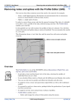
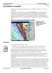
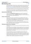
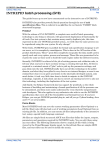
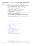
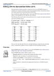
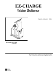
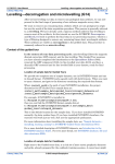
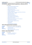
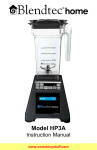
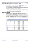
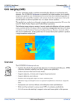
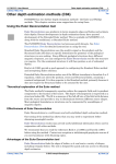
1
INTREPID User Manual
Library | Help | Top
Spectral domain (FFT) grid filters (G16)
1
| Back |
Spectral domain (FFT) grid filters (G16)
Top
The INTREPID Spectral (Fourier) Domain Grid Filter Tool (GridFFT) provides a
range of filtering options to generate the grid enhancement products that aid
interpretation. The tool delivers fast graphical feedback in both the spatial and
frequency domains, and also displays radial power spectra. The following
illustrations shows the GridFFT tool, firstly for standard scalar magnetic data, and
then secondly, automatically adapting to a Full Tensor Gravity gradiometry grid. The
process illustrated is an integration of the tensor to estimate a Gz signal.
Library | Help | Top
© 2012 Intrepid Geophysics
| Back |
INTREPID User Manual
Library | Help | Top
Spectral domain (FFT) grid filters (G16)
2
| Back |
Overview
GridFFT operates in the Fourier domain, transforming your grid dataset using a
Fast Fourier Transform (FFT) and enables you to:
•
Enhance grid datasets using a range of available FFT filters,
•
Process extremely large grid datasets,
•
Gain an insight into the filtering process by observing the graphical feedback,
•
Process full tensor & FALCON grid datasets.
Spectral Domain Grid Filters generally separate local phenomena from those
characteristic of the region as a whole.
This guided tour demonstrates some standard INTREPID Spectral Domain grid
filters. You can use the INTREPID Visualisation Tool to view the grid before and
after each process if you wish.
Filters supported
Currently GridFFT provides the following filters:
Low Pass, High Pass, Band Pass, Horizontal Derivative, Vertical Derivative,
Reduction to Pole or Equator, Analytic Signal, Total Horizontal Derivative,
Directional Cosine, Hilbert Transform, Pseudogravity, Matched Filter, Tensor
Queries, Tilt Angles.
For Full Tensor Grids: Low Pass, High Pass, Band Pass, Integration to Gz and
Reduction to Pole.
For FALCON: Optimized padding, Integration to estimate Gz, Find Gzz, Phase
checking of instrument calibration.
Context of this guided tour
In the context of your data processing cycle, this tour represents further
enhancement of data that has already had its noise, spikes and faulty flight path
segments removed, been decorrugated and microlevelled, then gridded.
Location of sample data for Guided Tours
We provide two complete sets of sample datasets, one in INTREPID format and one
in Geosoft format. INTREPID works equally well with both formats. When you want
to open a dataset, navigate to the directory containing the required data format.
Where install_path is the path of your INTREPID installation, the project
directories for the Guided Tours sample data are
install_path\sample_data\guided_tours\intrepid_datasets and
install_path\sample_data\guided_tours\geosoft_datasets.
For example, if INTREPID is installed in
C:\Program Files\Intrepid\Intrepid4.5.nnn,
then you can find the INTREPID format sample data at
C:\Program Files\Intrepid\Intrepid4.5.nnn\sample_data\
guided_tours\intrepid_datasets
This is the default location for the sample data. If you have installed INTREPID
normally, the data resides there. If you have installed INTREPID elsewhere, the
exercises will work just as well. Just use the appropriate pathnames.
Library | Help | Top
© 2012 Intrepid Geophysics
| Back |
INTREPID User Manual
Library | Help | Top
Spectral domain (FFT) grid filters (G16)
3
| Back |
For more information about installing the sample data, see "Sample datasets—
installing, locating, naming" in INTREPID Guided Tours Introduction (G01)
For a more detailed description of INTREPID datasets, see Introduction to the
INTREPID database (G20). For even more detail, see INTREPID database, file and
data structures (R05).
Location of sample data for CookBooks
Right next to the Guided tours data, is a rich set of more exotic geophysics datasets
and grids, already prepared for the cookbook training sessions. A casual user might
also gain some trial and error insights into the capbilities of the software, just by
testing the Project Manger’s ability to preview and describe the attributes of each of
the cookbook datasets.
Should you complete this guided tour?
This guided tour is intended for intermediate level users. Its process is more complex
than that of an introductory tour and its instructions are less detailed. If you are a
beginner or wish only to have a brief overview of INTREPID’s capabilities, you can
omit this guided tour. Spectral domain (FFT) grid filtering is, however, a
fundamental geophysical data process. You should not omit it from a thorough
evaluation of INTREPID’s capabilities.
What you will do
Flowchart Summary
Inputs
Process
Outputs
Grid
datasets
Specify filters
New Grid
dataset
Examine
Power
Spectum
Library | Help | Top
© 2012 Intrepid Geophysics
| Back |
INTREPID User Manual
Library | Help | Top
Spectral domain (FFT) grid filters (G16)
4
| Back |
Steps to follow
The following table summarises the output files, filters and parameters to be used.
Filter
Parameters
Input dataset
Output dataset
you create
Solution
dataset
supplied
Vertical
derivative
Order 1.0
mlevel_grid
vd_grid1
vd_grid
Directional
cosine filter
Direction 135, Cosine
function degree 2, Pass
option.
mlevel_grid
dircos_grid1
dircos_grid
Launch the
Spectral
Domain Filters
tool
Load the input
grid dataset
1
2
Start the Project Manager. Navigate to the directory
install_path\sample_data\guided_tours\intrepid_datasets\. Start
the Spectral Domain Grid Filters tool by choosing Grid_FFT from the Filtering
menu.
INTREPID displays an Open dialog box, requiring you to enter the name of the
input grid you wish to filter.
Specify mlevel_grid as the input dataset and click Open. The INTREPID
GridFFT window appears.
You can specify the input, output and parameters for the Vertical Derivative filter
process in this guided tour using the job file ch14_1.job. If you wish, load it into the
Spectral Domain Grid Filters tool as described in Section "Task specification (job) file
Library | Help | Top
© 2012 Intrepid Geophysics
| Back |
INTREPID User Manual
Library | Help | Top
Spectral domain (FFT) grid filters (G16)
5
| Back |
short cuts" in INTREPID Guided Tours Introduction (G01), then go to Step 5.
Choose a
Vertical
Derivative
filter
3
Specify a 1st order Vertical Derivative filter
From the list of Available FFT Filters on the left hand side, highlight Vertical
Derivative. Add the filter to the filtering process by clicking on the upper >
button. The filter description will appear in the box labelled Filtering Process.
In the right hand side panel, INTREPID will display the Vertical Derivative
Properties. Choose the default setting of order 1. You can specify any integer
order up to a maximum of 10.
4
Specify vd_grid1 as the output dataset.
In the panel labelled Filtering Process, highlight the Output Grid Dataset entry.
The display parameters in the right hand panel will change to reflect your choice.
The output Filtered Grid is given a default name of mlevel_grid_FILT. You can
change this output file name by clicking on the small box to the right of the name.
A chooser will appear. Type in the name vd_grid1 and click Save As. The
Filtered Grid Name will be updated to reflect your choice.
Apply the filter
process
5
Apply the filter and observe the process in the Grid Filter window.
Choose Apply in the Grid Filter window. INTREPID will apply the filter, save the
output dataset and display a Spatial View representation of the filter process in
the window.
Click on the Spectral Image View tab or the Spatial View tab to toggle between the
Spatial and Fourier representations of the input and output datasets.
Library | Help | Top
© 2012 Intrepid Geophysics
| Back |
INTREPID User Manual
Library | Help | Top
Spectral domain (FFT) grid filters (G16)
6
| Back |
Viewing the Radial Power Spectrum Graph
View the radial
power
spectrum
6
Measure depth
of a spectrum
segment
7
Library | Help | Top
View the Radial Power Spectrum graph
By choosing Radial Power Spectrum you can observe the Log Power versus
Wavenumber or Wavelength distributions for the input and output datasets.
There are options to access this same data in a csv file, and to also pass a moving
window around your grid, over each anomaly, so that individual bodies can be
tested.
Toggle between Wavenumber and Wavelength to alter the display
At the top of the tool there are buttons which will toggle the display between
Wavenumber and Wavelength. The x 1 and x 1000 buttons toggle the
Wavenumber display between cy/m and cy/km, and the Wavelength display
between m and km.
© 2012 Intrepid Geophysics
| Back |
INTREPID User Manual
Library | Help | Top
8
Spectral domain (FFT) grid filters (G16)
7
| Back |
(Optional– Compare the results with the original grid:) Compare the original grid
(mlevel_grid) and the solution dataset provided (vd_grid) using a sun angle
display in the Windows Visualisation Tool or UNIX Visualisation tool.
You can task switch to the Project Manager, start the Windows Visualisation Tool
or UNIX Visualisation tool and view the datasets immediately or wait until you
have finished this guided tour. (Note: vd_grid is a solution dataset provided by
us, which is identical to vd_grid1.) See Visualisation tools(G05) for visualisation
tool instructions.
Tip: You can launch two copies of the tool, load a different grid into each one and
place them side by side on the screen for best comparison.
Before vertical derivative filter
mlevel_grid
After vertical derivative filter
vd_grid
Using a Directional Cosine filter
You can specify the input, output and parameters for the Directional Cosine filter
process in this section of the guided tour using the job file ch14_2.job. If you wish,
load it into the Spectral Domain Grid Filters tool as described in Section "Task
specification (job) file short cuts" in INTREPID Guided Tours Introduction (G01), then
go to Step 11.
Specify a new
output dataset
9
Clear the current filter and specify a Directional Cosine filter
In the Filtering Process panel, highlight the current filter. Remove the filter from
the Filtering Process panel by clicking on the < button. From the list of Available
FFT Filters on the left hand side, highlight Directional Cosine. Add the filter to
the filtering process by clicking on the upper > button. The filter name appears in
the box labelled Filtering Process.
In the right hand side panel, INTREPID displays the Directional Cosine
Properties. Specify an Azimuth of 135°, an Azmiuthal Half Width of 60 degrees
and a Cosine Rolloff Degree of 2. Select the Pass option button. You can vary the
Library | Help | Top
© 2012 Intrepid Geophysics
| Back |
INTREPID User Manual
Library | Help | Top
Spectral domain (FFT) grid filters (G16)
8
| Back |
angular extent dramatically, and get very different filter responses with this
factor.
Library | Help | Top
© 2012 Intrepid Geophysics
| Back |
INTREPID User Manual
Library | Help | Top
Select the
directional
cosine filter
and set
parameters
Apply the filter
process
Library | Help | Top
Spectral domain (FFT) grid filters (G16)
9
| Back |
10 Specify dircos_grid1 as the new output dataset.
In the panel labelled Filtering Process, highlight the Output Grid Dataset entry.
The display parameters in the right hand panel will change to reflect your choice.
Click the small box to the right of the name. A Save As dialog box will appear.
Type in the name dircos_grid1 and click Save As. The Filtered Grid Name will
be updated to reflect your choice.
11 Apply the filter and observe the process in the Grid Filter window
Choose Apply in the Grid Filter window. INTREPID will apply the filter, save the
output dataset and display a Spatial View representation of the filter process in
the window.
© 2012 Intrepid Geophysics
| Back |
INTREPID User Manual
Library | Help | Top
Compare the
original and
filtered grids
Spectral domain (FFT) grid filters (G16)
10
| Back |
12 (Optional– Compare the results with the original grid:) Compare the original grid
(mlevel_grid) and the solution dataset provided (dircos_grid) using a sun
angle display in the Visualisation Tool.
You can task switch to the Project Manager, examine the thumbnail views or
start the Visualisation Tool and view the datasets immediately or wait until you
have finished this guided tour. (Note: dircos_grid is a solution dataset
provided by us, which is identical to dircos_grid1.) See Visualisation tools(G05)
for visualisation tool instructions.
Tip: You can launch two copies of the tool, load a different grid into each one and
place them side by side on the screen for best comparison.
Before directional cosine filter
mlevel_grid
After directional cosine filter
dircos_grid
13 Create a difference grid:
Exit
Load both grids into the spreadsheet editor. Use Create Field to subtract one grid
from the other and store its result in a diff.ers grid.
14 Exit from the Grid FFT tool.
From the File menu choose Quit.
Tensor Gradient Filters
INTREPID have developed several quite distinct workflows and algorithmic
strategies for dealing with aspects of tensor gradients. Challenges include padding
strategies, minimum operations counts to perform a FTG FFT transform, designing
transfer functions to integrate several gradient components to recover as much of the
original vector components of gravity as possible. This last one is well worth some
reflection. It is commonly thought that integrating Gzz to estimate Gz does the job WRONG!. At the very least the other two partial differentials of Gz, ie Gxz and Gyz
typically contain at least one third of the total original signal as rotational or
torsional contributions. So if your favourite instrument did not measure all the tensor
gradients, you are bound not to be able to recover all the original magnitude. A
special discussion about FALCON is warrented however. The Hilbert pair of
horizontal gradient components that is measured in this system, directly contains the
full Gzz signal magnitude, due to a close relationship with the LaPlace trace
condition. ie
Horizontal Curvature Gradient ( Guv + Gne) <=> Gzz
Library | Help | Top
© 2012 Intrepid Geophysics
| Back |
INTREPID User Manual
Library | Help | Top
Spectral domain (FFT) grid filters (G16)
11
| Back |
LaPlace Trace Gxx + Gyy + Gzz = 0;
In this discussion, there is still the factor of the missing Gzx & Gyz measures, when
the integration to Gz is attempted.
Filter operations supported
Low Pass, High Pass, Band Pass, Butterworth, Continuation, Integration. The all
important sign convention for the field components completely dominates the result
that is achieved, so it is very easy to make an error here, if you are not careful. Hence
, you are given direct access to a GUI component to experiment with the END/NED/
ENU state, so that you can also examine the consequences of getting this wrong.
Tensor Integration example
The sample_datasets/cookbook/tensors/Aurizonia/.A_2_Grids contains a tensor grid
from Brazil.
1
Launch grid filter from the project manager tool. Choose the grid dataset
aurizonia_T_fa_tensor_mitre.ers. The tensor Field components coordinate
reference frame is shown in the RED circle, as END, or East North Down. This is
the normal left handed convention used by Bell Geoscience.
2
Library | Help | Top
From the Filter Panel on the left, choose the FullTensorIntegration Query. There
is a drop down box that gives the inegration options. The default is to use Tez,
Tnz, Tzz to estimate Tz. As we are doing a gravity gradient grid, you should also
© 2012 Intrepid Geophysics
| Back |
INTREPID User Manual
Library | Help | Top
Spectral domain (FFT) grid filters (G16)
12
| Back |
convert from Eotvos back to mGal. This involves dividing the result by 10000.
Library | Help | Top
3
Set the output grid dataset name by clicking in the middle panel, on the last
entry. This switches to the output name panel. Type in aurizonia_Tz.ers
4
Now hit the Apply button, and watch the integration process being calculated,
then reported in the right hand side bottom panel.
5
Examine the Spectral Image view for a tensor grid. This contains two eigenvalue
grids plus the rotational or Phase grid. This is on the left hand side, representing
a full accounting of the tensor griud signal expressed in the least number of
independent grids possible. The justification for this statement, is that the
invariant properties of a tensor can be found by doing a principal
componentsanalysis, or in other words, solving the eigenvalue system, and
keeping track of the 3D rotations required at each point in the grid. As the
LaPlace relationship also holds for the eigenvalues, any two eigenvalues also
holds the third, hence the need to only show two amplitude grids. The rotational
transform can be expressed in Quaternion form and INTREPID chooses to show
just one manifestation of this data in grid form, the so called Phase. There is also
a MODULO and an EigenAxis display for this rotational data we are not showing.
These however, can be seen via the Visualization tool is required. The FFT tensor
grid is stored behind the scenes as a 12 band ERMapper grid, carrying complex
coefficients.
6
INTREPID suggest you repeat this exercise, this time varying the number of
partial derivative gradient components in the integration, and also varying the
© 2012 Intrepid Geophysics
| Back |
INTREPID User Manual
Library | Help | Top
Spectral domain (FFT) grid filters (G16)
13
| Back |
END/NED/ENU setting, to explore how misleading the answer can be, , if you
have a wrong setting for this work.
Other filters you can try
The following table contains a list of filters, suggested parameters and required
output dataset names for some further Spectral Domain Grid Filter exercises that
you may wish to complete. In each case, use mlevel_grid as the input dataset.
Filter
Parameters
Output dataset
you create
Solution
dataset
supplied
Upward
Continuation
ch14_3.job
250m
uw_grid1
uw_grid
Downward
Continuation
ch14_4.job
Continuation level = 80m, Use Damping,
Damping degree = 5
dw_grid1
dw_grid
Library | Help | Top
© 2012 Intrepid Geophysics
| Back |
INTREPID User Manual
Library | Help | Top
Reduction to the
Pole
ch14_5.job
Spectral domain (FFT) grid filters (G16)
14
| Back |
Calculate Earth’s magnetic field by clicking
IGRF in Reduction Properties panel.
rtp_grid1
rtp_grid
pass_grid1
pass_grid
Enter parameters: Year: 1990.8, Altitude =
0.1 km
Choose OK. INTREPID loads correct
parameters automatically into the Reduction
Properties.
High Pass filter
ch14_6.job
Cutoff = .0025 cy/m, Default rolloff
Under the name of each filter is the corresponding job file that you can use to
automatically specify the task. If you wish to use a job file, repeat steps 9–12 loading
the required job file into the Spectral Domain Grid Filters tool as described in Section
"Task specification (job) file short cuts" in INTREPID Guided Tours Introduction
(G01), then choose Apply. Examine the results using a visualisation tool if required.
You can find detailed instructions for using the filters in INTREPID General
Reference.
Key points for this guided tour
In this guided tour you used the Spectral Domain Filter tool to:
•
Transform a grid dataset to the Fourier domain using a Fast Fourier Transform,
•
Enhance the grid using
•
•
A 1st vertical derivative
•
A directional cosine filter
•
One or more other filters
Transform the enhanced grids back to the spatial domain
After applying the filters you could have examined the results using a visualisation
tool.
Frequently Asked Questions
Q : Can I process large grids?
A : The INTREPID FFT Grid Filter tool supports very large grids through the
implementation of tiling methods.
Q : Do I have to repeat the FFT process every time I use the FFT Grid Filter
tool?
A : No. When you first use it on a grid dataset INTREPID saves a copy of the
transformed dataset, which it can use from that point onwards.
Q : How can I find out the Nyquist frequency for a grid?
A : The tool automatically computes the Nyquist and Fundamental frequencies for the
input grid.
Q : I want to design a low pass filter in terms of wavelengths, not frequencies.
A : The tool allows you to toggle between the frequency and wavelength domains. The
filter parameters will be adjusted automatically.
Library | Help | Top
© 2012 Intrepid Geophysics
| Back |
INTREPID User Manual
Library | Help | Top
Spectral domain (FFT) grid filters (G16)
15
| Back |
Q : Can I run the filter as a batch job?
A : The INTREPID batch language provides full support for this tool.
Q : Can I transform standard gravity grid into curvature gradient grids?
A : Yes, use Tensor Query to select the curvature gradient option you require.
Library | Help | Top
© 2012 Intrepid Geophysics
| Back |