1
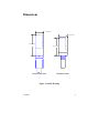
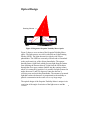
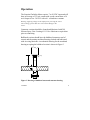
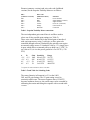
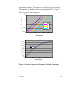
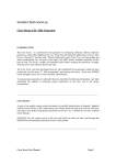
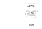
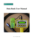
Seapoint
Turbidity
Meter
User Manual
07/2013
Dimensions
1.00" (25.4mm)
1.00" (25.4mm)
2.62" (66.5mm)
2.22" (56.4mm)
Connector versions
Bulkhead version
Figure 1. Outline Drawing
7/29/2013
2
Specifications
•
•
•
•
•
•
•
•
•
•
•
•
•
•
•
•
Power Requirements: 7-20VDC, 3.5mA avg, 6mA pk
Output: 0-5.0 VDC
Output Impedence: 1000 ohms
Output Time Constant: 0.1 sec
RMS Noise: < 1 mV
Power-up Transient Period: <1 sec
Light Source Wavelength: 880 nm
Scattering Angles: 15 - 150 degrees (approx. 90 degree
peak sensitivity)
Linearity: ±2 % 0-1250 FTU, ±5% 0-1600 NTU
Sensitivity/Range:
100x gain:
200 mV/FTU
25 FTU
20x gain:
40 mV/FTU
125 FTU
5x gain:
10 mV/FTU
500 FTU
1x gain:
2 mV/FTU
4000 FTU *
* response above 1250 FTU becomes non-linear
Temperature Coefficient: < 0.05 %/°C
Operating Temperature: 0°C to 65°C
Depth Capability: 6000 m (19,700 ft)
Sensor Weight (dry): 80 g (3 oz)
Body Diameter: 2.5 cm (1.0 in)
Materials: Rigid polyurethane plastic and epoxy
7/29/2013
3
Introduction
The Seapoint Turbidity Meter is a sensor that measures turbidity
by detecting scattered light from suspended particles in water. Its
small size, very low power consumption, high sensitivity, wide
dynamic range, and 6000 meter depth capability allow this sensor
to be used in most applications where turbidity or suspended
particle concentrations are to be measured. The sensor is also
insensitive to ambient light when under water and has a very low
temperature coefficient.
The Seapoint Turbidity Meter senses scattered light from a small
volume within 5 centimeters of the sensor windows. Confining the
sensing volume allows the sensor to be calibrated in relatively
small water containers without errors from surface and wall
reflections. It also allows the sensor to be used in tight spaces such
as crowded instrumentation packages, pipes, and shallow streams.
Two control lines allow the user to externally set the sensitivity of
the Seapoint Turbidity Meter by choosing one of four gains. This
provides an easy means to set the sensitivity to provide the range
and resolution required for a particular application. Sensitivities of
2, 10, 40 and 200 mV/FTU are possible.
Each sensor is factory adjusted for consistent response to Formazin
Turbidity Standard measured in Formazin Turbidity Units (FTU).
The user may also calibrate the sensor with particles of interest to
measure suspended solids concentrations.
The Seapoint Turbidity Meter is constructed of rugged, corrosion
resistant materials and quality surface mount electronic
components for durability and high reliability.
7/29/2013
4
Optical Design
Sensing Volume
LED
Photodiode
Figure 2. Diagram of Seapoint Turbidity Meter Optics
Figure 2 shows a cross-section of the Seapoint Turbidity Meter
optics. The light sources are side-by-side 880 nm Light Emitting
Diodes (LEDs). The light detectors are side-by-side silicon
photodiodes. The LEDs are extremely efficient and well matched
to the peak sensitivity of the silicon photodiodes. The opaque
housing forms a light block which prevents light from the emitter
from reaching the detector directly. Light from the LEDs shines
through the clear epoxy emitter window into the sensing volume
where it is scattered by particles. It is possible for light scattered at
angles between 15 and 150 degrees to enter the detector’s
receiving cone and reach the photodiodes. The amount of scattered
light that reaches the detectors is proportional to the turbidity or
particle concentration in the water over a very large range.
The optical design of the Seapoint Turbidity Meter is unique in its
restriction of the angle of emission of the light sources and the
7/29/2013
5
angle of detection of the light detectors. This confines the sensing
volume to within five centimeters of the sensor windows. The
advantage of confining the sensing volume to a small space near
the sensor is the great reduction of interference from reflections
from large objects outside the sensing volume. This allows the
sensor to be calibrated in a relatively small water container without
interference from surface or wall reflections. It also allows the
sensor to be used where limited volume of water exists for sensing
or in the midst of objects that would otherwise cause interfering
reflections. Examples include instrumentation packages with
limited space between instruments or limited space inside the
frame, monitoring water inside pipes, and measuring water in
shallow streams or very close to the bed of a water body.
7/29/2013
6
Electronic Design
The Seapoint Turbidity Meter has an electronic design that
achieves high sensitivity while consuming very little power.
Micropower components are used so that most of the power drawn
by the sensor is used to drive the LEDs. Overall power
requirements are 7-20 VDC, 3.5 mA average, 6 mA peak. Optical
feedback is used in the light source drive circuitry. This offers
several benefits including excellent temperature compensation for
the optical components, compensation for the aging of the optical
components, and stable output within a second after power up.
The light source is modulated, and synchronous detection is used
to extract the scattering signal from the overall signal, removing
the ambient light component and most of the electronic noise.
Achieving high sensitivity using low power was accomplished by
paying careful attention to proper circuit board layout to prevent
any stray coupling of signals synchronous with the modulation of
the light source into the detection circuitry. The need for offset
adjustment was thereby eliminated — the offset voltage for this
sensor at any gain is within one millivolt of zero.
7/29/2013
7
Operation
The Seapoint Turbidity Meter requires 7 to 20 VDC input and will
draw an average of 3.5 mA current with a peak current draw of 6
mA. Output is 0 to 5.0 VDC with a 0.1 second time constant.
Warning: Applying voltages to the output pin or powering the sensor
with a voltage greater than 20 V will result in damage to the
sensor.
Connector versions should be cleaned and lubricated with 3M
Silicone Spray, Dow Corning #111 Valve Lubricant or equivalent
prior to connecting.
Bulkhead versions should have the bulkhead (connector end of
sensor) and the mating machined housing cleaned and lubricated
with an o-ring lubricant. A mechanical drawing for the machined
housing accepting the bulkhead version is shown in Figure 3.
o-rings
1.5
1/2-20
0.28
0.500
0.562+.002
-.000
Figure 3. Drawing of bulkhead sensorand customer housing.
7/29/2013
8
Pinouts (connector versions) and wire color code (bulkhead
versions) for the Seapoint Turbidity Meter are as follows:
Pin #
(connector versions)
Pin 1
Pin 2
Pin 3
Pin 4
Pin 5
Pin 6
Wire color
(bulkead versions)
Brown
Blue
Green
Yellow
Orange
Red Gain
Function
Power Ground
Signal Output (0-5VDC)
Signal Ground
Power In (7-20VDC)
Gain Control A
Control B
Table 1. Seapoint Turbidity Meter connections
The two independent gain control lines A and B are used to
select one of four possible gain settings (see Table 2).
These wires can be hardwired for the desired gain or interfaced
with a microprocessor, using 5 volt logic, to allow gain to be
controlled through software. Hardwiring the gain does not require
an external voltage source. To hardwire a line to +5V, simply leave
it open, which allows an internal pull-up to hold it at +5 VDC. To
set a line to 0V, tie it to the power ground. n/a 2 mV/FTU (<750
FTU)
A
+5 V
+5 V
0V
0V
B
+5 V
0V
+5 V
0V
Gain
100X
20X
5X
1X
Sensitivity
200 mV/FTU
40 mV/FTU
10 mV/FTU
2 mV/FTU
Range
25 FTU
125 FTU
500 FTU
4000 FTU*
* response becomes nonlinear above 1250 FTU
Table 2. Truth Table for Switching Gains
The sensor linearity in Formazin is ±2 % at the 100X,
20X, and 5X gain settings. The 1X gain setting is used in
extremely turbid water. The sensor response above 1250 FTU
becomes nonlinear; however, the useful range can be extended by
calibrating the sensor and fitting the response with a second order
7/29/2013
9
polynomial equation. This approach is limited by the increasingly
flat response at turbidity levels approaching 4000 FTU. Figure 4
shows a typical sensor response.
Sensor Output (Volts)
10
1
100X
0.1
20X
5X
0.01
0.001
0.01
1X
0.1
1
10
100
1000
10000
Sensor Output (Volts)
Turbidity (FTU)
5
4.5
4
3.5
3
2.5
2
1.5
1
0.5
0
1X
0
1000
2000
3000
4000
Turbidity (FTU)
Figure 4. Sensor Response to Formazin Turbidity Standard
7/29/2013
10
Calibration
All sensors are adjusted to the nominal sensitivities specified so
that for most purposes they are interchangeable. If greater accuracy
is desired, it is recommended that the user perform calibrations on
individual sensors.
The sensors can also be calibrated by the user to measure
suspended solids concentrations. Like other optical turbidity
sensors, this calibration must be performed using a sample from
the measurement site. Calibrations with different particle types will
typically result in different values for sensitivity (V/(mg/l)).
Calibrations should be performed periodically at a frequency
which depends on the condition of the windows. Although these
sensors are electronically stable with time, scratching or fouling of
the windows will result in reduced sensitivity. Visual inspection is
a good test of whether the sensor needs recalibration: if the
windows appear polished and clear when dry, the sensitivity
probably has not degraded significantly.
When calibrating in a small container, multiple scattering events
may reflect off the container walls introducing a small error to the
calibration. For this reason, the use of a black container is
recommended. Calibration should be performed under fluorescent
or LED lighting. Incandescent lights emit large amounts of energy
at the operating wavelength which may interfere with
measurements.
7/29/2013
11
Care
The Seapoint Turbidity Meter is a rugged instrument that should
provide years of reliable performance with minimal care. After
using, rinse the sensors and clean the windows with water and mild
detergent if necessary (avoid using organic solvents). If windows
become scratched, they may be polished using a cloth buffing
wheel with polishing compound.
The connectors should be lubricated before each use with 3M
silicone Spray, Dow Corning #111 Valve Lubricant or equivalent.
The Seapoint Turbidity Meter contains no user serviceable
electronics and must be returned to the factory if it does not
operate properly.
Limited Warranty
Seapoint Sensors, Inc. warrants this Turbidity Meter to be free of defects of materials and
workmanship under normal use and service for a period of 1 year from the date of
shipment. This warranty extends only to the original purchaser. In the event the product
fails to operate according to our published specifications during the warranty period,
Seapoint Sensors, Inc. will repair or replace the instrument at our discretion. If it is
determined that the failure was due to other than normal use or service, repairs will be
billed and estimate will be submitted prior to repair work. Shipping costs must be
prepaid. Seapoint Sensors, Inc. accepts no responsibility for damage during return
shipment.
7/29/2013
12
Seapoint Sensors, Inc.
P.O. Box 368
Exeter, NH 03833 USA
7/29/2013
Tel:503-642-4921
[email protected]
www.seapoint.com
13